

A word from me as an electronics instructor and who has long been in the world of electronics and energy transport
Power supply is an important requirement in an electronic equipment because all the energy requirements in electronic equipment are affected and given energy by the power supply; the electron energy is given either by push and pull forces and the shear stresses on the electrons are also the impetus to make electron eleastisitas penetrate an electronic component both passive components (resistor, inductor and capacitor) and process components (diode, transistor, IC: linear IC - Digital IC - IC timer - IC Regulator, microprocessor; zilog 80 - 8086 processor - 8088 - 80286 - 80386 SX / DX and others, microcontroler: there are many microprocessors controlled by the clock and feedback systems usually accompanied hardware and continuous programs). the development of the power supply requirement for small and dynamic, elastic surface mount technology components is a necessity that must and must be possessed by a super sophisticated electronic equipment system because development now requires such a thing especially for the future development of tactical vehicle vehicles, a time to minimize the need through battery or battery energy for cars and airplanes; we know that the linear power supply requirement for high efficiency is very expensive and has a very large physical form and tend to make electronics equipment become inflexible and dynamic for it is required switch mode power supply for component components of surface mount technology is very small and dynamic and does not require a large body system and more efficient and easy to move the equipment because the physical and unique system, flexible and dynamic and mobile system.
XXX . XXX LINEAR POWER SUPPLY
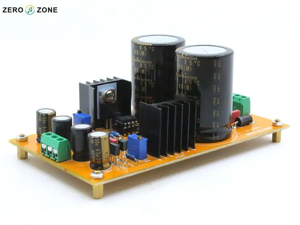


Linear power supplies are widely used because of the advantages they offer in terms of overall performance.
Linear regulated power supplies are often used in exacting situations where the regulation and removal of noise is paramount.
While linear power supplies may not be as efficient as other types of power supply technology, they offer the best performance and are therefore used in many applications where noise is of great importance. Often audio amplifiers and many other items of electronic equipment use linear power supplies to obtain the best performance.
Linear power supply basics
Linear regulated power supplies gain their name from the fact that they use linear, i.e. non-switching techniques to regulate the voltage output from the power supply. The term linear power supply implies that the power supply is regulated to provide the correct voltage at the output. Sometimes the sensing of the voltage may be accomplished at the output terminals, or on some occasions it may be achieved directly at the load.
In terms of the overall make-up of a linear power supply, it can be split into several blocks as detailed below.
The main elements of the linear power supply are:
- Input transformer: As many regulated power supplies take their source power from an AC mains input, it is common for linear power supplies to have a step down or occasionally a step up transformer. This also serves to isolate the power supply from the mains input for safety.

- Rectifier: As the input from an AC supply is alternating, this needs to be converted to a DC format. Various forms of rectifier circuit are available.Even for DC powered regulators, a rectifier may be placed at the input to guard against inverse connection of the supply.
Note on Diode Rectifier Circuits:
Diode rectifier circuits are used in many areas from mains power supplies to radio frequency demodulation. The diode rectifier circuits use the capability of the diode to only pass current in one direction. There are several varieties from half wave to full wave, bridge rectifiers, peak detectors and more. - Smoothing: Once rectified from an AC signal, the DC needs to be smoothed to remove the varying voltage level. Large reservoir capacitors are used for this.

Smoothing action of a reservoir capacitor - Linear regulator: Once a smoothed supply is available, this can then be applied to the linear regulator. This will provide a properly regulated output.
Linear power supply regulators
There are two main types of linear power supply:
- Shunt regulator: The shunt regulator is less widely used as the main element within a voltage regulator. For this form of linear power supply, a variable element is placed across the load. There is a source resistor placed in series with the input, and the shunt regulator is varied to ensure that the voltage across the load remains constant. Read more about the Shunt regulator
- Series regulator: This is the most widely used format for a linear power supply. As the name implies a series element is placed in the circuit, and its resistance varied via the control electronics to ensure that the correct output voltage is generated for the current taken.
Both of these types of linear regulator used in power supplies has its uses and can be used in different situations.
Linear power supply advantages / disadvantages
The use of any technology is often a careful balance of several advantages and disadvantages. This is true for linear power supplies which offer some distinct advantages, but also have their drawbacks.
Linear PSU advantages
- Established technology: Linear power supplies have been in widespread use for many years and their technology is well established and understood.
- Low noise: The use of the linear technology without any switching element means that noise is kept to a minimum and the annoying spikes found in switching power supplies are now found.
- Linear PSU disadvantage
- Efficiency: In view of the fact that a linear power supply uses linear technology, it is not particularly efficient. Efficiencies of around 50% are not uncommon, and under some conditions they may offer much lower levels.
- Heat dissipation: The use of a series or parallel (less common) regulating element means that significant amounts of heat are dissipated and this needs to be removed.
- Size: The use of linear technology means that the size of a linear power supply tends to be larger than other forms of power supply.
Despite the disadvantages, linear regulated power supply technology is still widely used, although it is more widely used where low noise and good regulation are needed. One typical application is for audio amplifiers where the linear supply is able to provide optimum performance for powering all the stages of the amplifier.
Despite the disadvantages, linear regulated power supply technology is still widely used, although it is more widely used where low noise and good regulation are needed. One typical application is for audio amplifiers where the linear supply is able to provide optimum performance for powering all the stages of the amplifier.
Power supply
A power supply is an electrical device that supplies electric power to an electrical load. The primary function of a power supply is to convert electric current from a source to the correct voltage, current, and frequency to power the load. As a result, power supplies are sometimes referred to as electric power converters. Some power supplies are separate standalone pieces of equipment, while others are built into the load appliances that they power. Examples of the latter include power supplies found in desktop computers and consumer electronics devices. Other functions that power supplies may perform include limiting the current drawn by the load to safe levels, shutting off the current in the event of an electrical fault, power conditioning to prevent electronic noise or voltage surges on the input from reaching the load, power-factor correction, and storing energy so it can continue to power the load in the event of a temporary interruption in the source power (uninterruptible power supply).
All power supplies have a power input connection, which receives energy in the form of electric current from a source, and one or more power output connections that deliver current to the load. The source power may come from the electric power grid, such as an electrical outlet, energy storage devices such as batteries or fuel cells, generators or alternators, solar power converters, or another power supply. The input and output are usually hardwired circuit connections, though some power supplies employ wireless energy transfer to power their loads without wired connections. Some power supplies have other types of inputs and outputs as well, for functions such as external monitoring and control.

General classification

Functional
Power supplies are categorized in various ways, including by functional features. For example, a regulated power supply is one that maintains constant output voltage or current despite variations in load current or input voltage. Conversely, the output of an unregulated power supply can change significantly when its input voltage or load current changes. Adjustable power supplies allow the output voltage or current to be programmed by mechanical controls (e.g., knobs on the power supply front panel), or by means of a control input, or both. An adjustable regulated power supply is one that is both adjustable and regulated. An isolated power supply has a power output that is electrically independent of its power input; this is in contrast to other power supplies that share a common connection between power input and output.
Packaging
Power supplies are packaged in different ways and classified accordingly. A bench power supply is a stand-alone desktop unit used in applications such as circuit test and development. Open frame power supplies have only a partial mechanical enclosure, sometimes consisting of only a mounting base; these are typically built into machinery or other equipment. Rack mount power supplies are designed to be secured into standard electronic equipment racks. An integrated power supply is one that shares a common printed circuit board with its load. An external power supply, AC adapter or power brick, is a power supply located in the load's AC power cord that plugs into a wall outlet; a wall wart is an external supply integrated with the outlet plug itself. These are popular in consumer electronics because of their safety; the hazardous 120 or 240 volt mains current is transformed down to a safer voltage before it enters the appliance body.
Power conversion method
Power supplies can be broadly divided into linear and switching types. Linear power converters process the input power directly, with all active power conversion components operating in their linear operating regions. In switching power converters, the input power is converted to AC or to DC pulses before processing, by components that operate predominantly in non-linear modes (e.g., transistors that spend most of their time in cutoff or saturation). Power is "lost" (converted to heat) when components operate in their linear regions and, consequently, switching converters are usually more efficient than linear converters because their components spend less time in linear operating regions.
Types
DC power supply
A DC power supply is one that supplies a constant DC voltage to its load. Depending on its design, a DC power supply may be powered from a DC source or from an AC source such as the power mains.
AC-to-DC supply

DC power supplies use AC mains electricity as an energy source. Such power supplies will employ a transformer to convert the input voltage to a higher or lower AC voltage. A rectifier is used to convert the transformer output voltage to a varying DC voltage, which in turn is passed through an electronic filter to convert it to an unregulated DC voltage.
The filter removes most, but not all of the AC voltage variations; the remaining AC voltage is known as ripple. The electric load's tolerance of ripple dictates the minimum amount of filtering that must be provided by a power supply. In some applications, high ripple is tolerated and therefore no filtering is required. For example, in some battery charging applications it is possible to implement a mains-powered DC power supply with nothing more than a transformer and a single rectifier diode, with a resistor in series with the output to limit charging current.
Switched-mode power supply
In a switched-mode power supply (SMPS), the AC mains input is directly rectified and then filtered to obtain a DC voltage. The resulting DC voltage is then switched on and off at a high frequency by electronic switching circuitry, thus producing an AC current that will pass through a high-frequency transformer or inductor. Switching occurs at a very high frequency (typically 10 kHz — 1 MHz), thereby enabling the use of transformers and filter capacitors that are much smaller, lighter, and less expensive than those found in linear power supplies operating at mains frequency. After the inductor or transformer secondary, the high frequency AC is rectified and filtered to produce the DC output voltage. If the SMPS uses an adequately insulated high-frequency transformer, the output will be electrically isolated from the mains; this feature is often essential for safety.
Switched-mode power supplies are usually regulated, and to keep the output voltage constant, the power supply employs a feedback controller that monitors current drawn by the load. The switching duty cycle increases as power output requirements increase.
SMPSs often include safety features such as current limiting or a crowbar circuit to help protect the device and the user from harm. In the event that an abnormal high-current power draw is detected, the switched-mode supply can assume this is a direct short and will shut itself down before damage is done. PC power supplies often provide a power good signal to the motherboard; the absence of this signal prevents operation when abnormal supply voltages are present.
Some SMPSs have an absolute limit on their minimum current output.[2] They are only able to output above a certain power level and cannot function below that point. In a no-load condition the frequency of the power slicing circuit increases to great speed, causing the isolated transformer to act as a Tesla coil, causing damage due to the resulting very high voltage power spikes.Switched-mode supplies with protection circuits may briefly turn on but then shut down when no load has been detected. A very small low-power dummy load such as a ceramic power resistor or 10-watt light bulb can be attached to the supply to allow it to run with no primary load attached.
The switch-mode power supplies used in computers have historically had low power factors and have also been significant sources of line interference (due to induced power line harmonics and transients). In simple switch-mode power supplies, the input stage may distort the line voltage waveform, which can adversely affect other loads (and result in poor power quality for other utility customers), and cause unnecessary heating in wires and distribution equipment. Furthermore, customers incur higher electric bills when operating lower power factor loads. To circumvent these problems, some computer switch-mode power supplies perform power factor correction, and may employ input filters or additional switching stages to reduce line interference.
Linear regulator
The function of a linear voltage regulator is to convert a varying DC voltage to a constant, often specific, lower DC voltage. In addition, they often provide a current limiting function to protect the power supply and load from overcurrent (excessive, potentially destructive current).
A constant output voltage is required in many power supply applications, but the voltage provided by many energy sources will vary with changes in load impedance. Furthermore, when an unregulated DC power supply is the energy source, its output voltage will also vary with changing input voltage. To circumvent this, some power supplies use a linear voltage regulator to maintain the output voltage at a steady value, independent of fluctuations in input voltage and load impedance. Linear regulators can also reduce the magnitude of ripple and noise on the output voltage.
AC power supplies
In modern use, AC power supplies can be divided into single phase and three phase systems. "The primary difference between single phase and three phase AC power is the constancy of delivery." AC power Supplies can also be used to change the frequency as well as the voltage, they are often used by manufacturers to check the suitability of their products for use in other countries. 230V 50 Hz or 115 60 Hz or even 400 Hz for avionics testing.An AC power supply typically takes the voltage from a wall outlet (mains supply) and uses a transformer to step up or step down the voltage to the desired voltage. Some filtering may take place as well. In some cases, the source voltage is the same as the output voltage; this is called an isolation transformer. Other AC power supply transformers do not provide mains isolation; these are called autotransformers; a variable output autotransformer is known as a variac. Other kinds of AC power supplies are designed to provide a nearly constant current, and output voltage may vary depending on impedance of the load. In cases when the power source is direct current, (like an automobile storage battery), an inverter and step-up transformer may be used to convert it to AC power. Portable AC power may be provided by an alternator powered by a diesel or gasoline engine (for example, at a construction site, in an automobile or boat, or backup power generation for emergency services) whose current is passed to a regulator circuit to provide a constant voltage at the output. Some kinds of AC power conversion do not use a transformer. If the output voltage and input voltage are the same, and primary purpose of the device is to filter AC power, it may be called a line conditioner. If the device is designed to provide backup power, it may be called an uninterruptable power supply. A circuit may be designed with a voltage multiplier topology to directly step-up AC power; formerly, such an application was a vacuum tube AC/DC receiver.
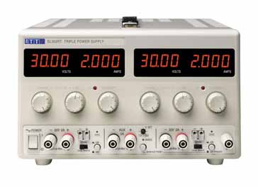
Programmable power supply

A programmable power supply is one that allows remote control of its operation through an analog input or digital interface such as RS232 or GPIB. Controlled properties may include voltage, current, and in the case of AC output power supplies, frequency. They are used in a wide variety of applications, including automated equipment testing, crystal growth monitoring, semiconductor fabrication, and x-ray generators.
Programmable power supplies typically employ an integral microcomputer to control and monitor power supply operation. Power supplies equipped with a computer interface may use proprietary communication protocols or standard protocols and device control languages such as SCPI.
Uninterruptible power supply
An uninterruptible power supply (UPS) takes its power from two or more sources simultaneously. It is usually powered directly from the AC mains, while simultaneously charging a storage battery. Should there be a dropout or failure of the mains, the battery instantly takes over so that the load never experiences an interruption. In a computer installation, this gives the operators time to shut down the system in an orderly way. Other UPS schemes may use an internal combustion engine or turbine to continuously supply power to a system in parallel with power coming from the AC. The engine-driven generators would normally be idling, but could come to full power in a matter of a few seconds in order to keep vital equipment running without interruption. Such a scheme might be found in hospitals or telephone central offices.
High-voltage power supply

A high-voltage power supply is one that outputs hundreds or thousands of volts. A special output connector is used that prevents arcing, insulation breakdown and accidental human contact. Federal Standard connectors are typically used for applications above 20 kV, though other types of connectors (e.g., SHV connector) may be used at lower voltages. Some high-voltage power supplies provide an analog input or digital communication interface that can be used to control the output voltage. High-voltage power supplies are commonly used to accelerate and manipulate electron and ion beams in equipment such as x-ray generators, electron microscopes, and focused ion beam columns, and in a variety of other applications, including electrophoresis and electrostatics.
High-voltage power supplies typically apply the bulk of their input energy to a power inverter, which in turn drives a voltage multiplier or a high turns ratio, high-voltage transformer, or both (usually a transformer followed by a multiplier) to produce high voltage. The high voltage is passed out of the power supply through the special connector and is also applied to a voltage divider that converts it to a low-voltage metering signal compatible with low-voltage circuitry. The metering signal is used by a closed-loop controller that regulates the high voltage by controlling inverter input power, and it may also be conveyed out of the power supply to allow external circuitry to monitor the high-voltage output.
Specification
The suitability of a particular power supply for an application is determined by various attributes of the power supply, which are typically listed in the power supply's specification. Commonly specified attributes for a power supply include:
- Input voltage type (AC or DC) and range
- Efficiency of power conversion
- The amount of voltage and current it can supply to its load
- How stable its output voltage or current is under varying line and load conditions
- How long it can supply energy without refueling or recharging (applies to power supplies that employ portable energy sources)
- Operating and storage temperature ranges
Power supply applications
Power supplies are a fundamental component of many electronic devices and therefore used in a diverse range of applications. This list is a small sample of the many applications of power supplies.
Computer power supply
A modern computer power supply is a switch-mode power supply that converts AC power from the mains supply, to several DC voltages. Switch-mode supplies replaced linear supplies due to cost, weight, and size improvement. The diverse collection of output voltages also have widely varying current draw requirements.
Electric Vehicle power supply
Electric vehicles are those which rely on energy created through electricity generation. A power supply unit is part of the necessary design to convert high voltage vehicle battery power.
Welding power supply
Arc welding uses electricity to join metals by melting them. The electricity is provided by a welding power supply, and can either be AC or DC. Arc welding requires high currents typically between 100 and 350 amperes. Some types of welding can use as few as 10 amperes, while some applications of spot welding employ currents as high as 60,000 amperes for an extremely short time. Welding power supplies consisted of transformers or engines driving generators; modern welding equipment uses semiconductors and may include microprocessor control.
Aircraft power supply
Both commercial and military avionic systems require either a DC-DC or AC/DC power supply to convert energy into usable voltage.
AC adapter

An AC adapter is a power supply built into an AC mains power plug. AC adapters are also known by various other names such as "plug pack" or "plug-in adapter", or by slang terms such as "wall wart". AC adapters typically have a single AC or DC output that is conveyed over a hardwired cable to a connector, but some adapters have multiple outputs that may be conveyed over one or more cables. "Universal" AC adapters have interchangeable input connectors to accommodate different AC mains voltages.
Adapters with AC outputs may consist only of a passive transformer (plus a few diodes in DC-output adapters), or they may employ switch-mode circuitry. AC adapters consume power (and produce electric and magnetic fields) even when not connected to a load; for this reason they are sometimes known as "electricity vampires", and may be plugged into power strips to allow them to be conveniently turned on and off.
Thermal Management
The power supply of an electrical system tends to generate much heat. The higher the efficiency, the more heat is pulled away from the unit. There are many ways to manage the heat of a power supply unit. The types of cooling generally fall into two categories -- convection and conduction. Common convection methods for cooling electronic power supplies include natural air flow, forced air flow, or other liquid flow over the unit. Common conduction cooling methods include heat sinks, cold plates, and thermal compounds.
Overload protection
Power supplies often have protection from short circuit or overload that could damage the supply or cause a fire. Fuses and circuit breakers are two commonly used mechanisms for overload protection.[6]
A fuse contains a short piece of wire which melts if too much current flows. This effectively disconnects the power supply from its load, and the equipment stops working until the problem that caused the overload is identified and the fuse is replaced. Some power supplies use a very thin wire link soldered in place as a fuse. Fuses in power supply units may be replaceable by the end user, but fuses in consumer equipment may require tools to access and change.
A circuit breaker contains an element that heats, bends and triggers a spring which shuts the circuit down. Once the element cools, and the problem is identified the breaker can be reset and the power restored.
Some PSUs use a thermal cutout buried in the transformer rather than a fuse. The advantage is it allows greater current to be drawn for limited time than the unit can supply continuously. Some such cutouts are self resetting, some are single use only.
Current limiting
Some supplies use current limiting instead of cutting off power if overloaded. The two types of current limiting used are electronic limiting and impedance limiting. The former is common on lab bench PSUs, the latter is common on supplies of less than 3 watts output.
A foldback current limiter reduces the output current to much less than the maximum non-fault current.
Terminology
- SCP - Short circuit protection
- OPP - Overpower (overload) protection
- OCP - Overcurrent protection
- OTP - Overtemperature protection
- OVP - Overvoltage protection
- UVP - Undervoltage protection
- UPS - Uninterruptable Power Supply
- PSU - Power Supply Unit
- SMPSU - Switch-Mode Power Supply Unit
XXX . XXX 5% zero Switched-mode power supply
A switched-mode power supply (switching-mode power supply, switch-mode power supply, switched power supply, SMPS, or switcher) is an electronic power supply that incorporates a switching regulator to convert electrical power efficiently. Like other power supplies, an SMPS transfers power from a DC or AC source (often mains power) to DC loads, such as a personal computer, while converting voltage and current characteristics. Unlike a linear power supply, the pass transistor of a switching-mode supply continually switches between low-dissipation, full-on and full-off states, and spends very little time in the high dissipation transitions, which minimizes wasted energy. Ideally, a switched-mode power supply dissipates no power. Voltage regulation is achieved by varying the ratio of on-to-off time. In contrast, a linear power supply regulates the output voltage by continually dissipating power in the pass transistor. This higher power conversion efficiency is an important advantage of a switched-mode power supply. Switched-mode power supplies may also be substantially smaller and lighter than a linear supply due to the smaller transformer size and weight.
Switching regulators are used as replacements for linear regulators when higher efficiency, smaller size or lighter weight are required. They are, however, more complicated; their switching currents can cause electrical noise problems if not carefully suppressed, and simple designs may have a poor power factor.
interior view of an ATX SMPS :
A: input EMI filtering and bridge rectifier;
B: input filter capacitors;
Between B and C: primary side heat sink;
C: transformer;
Between C and D: secondary side heat sink;
D: output filter coil;
E: output filter capacitors.
The coil and large yellow capacitor below E are additional input filtering components that are mounted directly on the power input connector and are not part of the main circuit board.

An adjustable switched-mode power supply for laboratory use
Flash Back
- 1836
- Induction coils use switches to generate high voltages.
- 1910
- An inductive discharge ignition system invented by Charles F. Kettering and his company Dayton Engineering Laboratories Company (Delco) goes into production for Cadillac.[1] The Kettering ignition system is a mechanically-switched version of a flyback boost converter; the transformer is the ignition coil. Variations of this ignition system were used in all non-diesel internal combustion engines until the 1960s when it began to be replaced first by solid-state electronically-switched versions, then capacitive discharge ignition systems.
- 1926
- On 23 June, British inventor Philip Ray Coursey applies for a patent in his country and United States, for his "Electrical Condenser". The patent mentions high frequency welding and furnaces, among other uses.
- ca 1932
- Electromechanical relays are used to stabilize the voltage output of generators. See Voltage regulator#Electromechanical regulators.
- ca 1936
- Car radios used electromechanical vibrators to transform the 6 V battery supply to a suitable B+ voltage for the vacuum tubes.
- 1959
- Transistor oscillation and rectifying converter power supply system U.S. Patent 3,040,271 is filed by Joseph E. Murphy and Francis J. Starzec, from General Motors Company[8]
- ca 1967
- Bob Widlar of Fairchild Semiconductor designs the µA723 IC voltage regulator. One of its applications is as a switched mode regulator.
- 1970
- Tektronix starts using High-Efficiency Power Supply in its 7000-series oscilloscopes produced from about 1970 to 1995.
- 1972
- HP-35, Hewlett-Packard's first pocket calculator, is introduced with transistor switching power supply for light-emitting diodes, clocks, timing, ROM, and registers.
- 1973
- Xerox uses switching power supplies in the Alto minicomputer
- 1977
- Apple II is designed with a switching mode power supply. "Rod Holt was brought in as product engineer and there were several flaws in Apple II that were never publicized. One thing Holt has to his credit is that he created the switching power supply that allowed us to do a very lightweight computer".
- 1980
- The HP8662A 10 kHz – 1.28 GHz synthesized signal generator went with a switched mode power supply.
Explanation
A linear regulator provides the desired output voltage by dissipating excess power in ohmic losses (e.g., in a resistor or in the collector–emitter region of a pass transistor in its active mode). A linear regulator regulates either output voltage or current by dissipating the excess electric power in the form of heat, and hence its maximum power efficiency is voltage-out/voltage-in since the volt difference is wasted.
In contrast, a switched-mode power supply changes output voltage and current by switching ideally lossless storage elements, such as inductors and capacitors, between different electrical configurations. Ideal switching elements (approximated by transistors operated outside of their active mode) have no resistance when "on" and carry no current when "off", and so converters with ideal components would operate with 100% efficiency (i.e., all input power is delivered to the load; no power is wasted as dissipated heat).

For example, if a DC source, an inductor, a switch, and the corresponding electrical ground are placed in series and the switch is driven by a square wave, the peak-to-peak voltage of the waveform measured across the switch can exceed the input voltage from the DC source. This is because the inductor responds to changes in current by inducing its own voltage to counter the change in current, and this voltage adds to the source voltage while the switch is open. If a diode-and-capacitor combination is placed in parallel to the switch, the peak voltage can be stored in the capacitor, and the capacitor can be used as a DC source with an output voltage greater than the DC voltage driving the circuit. This boost converter acts like a step-up transformer for DC signals. A buck–boost converter works in a similar manner, but yields an output voltage which is opposite in polarity to the input voltage. Other buck circuits exist to boost the average output current with a reduction of voltage.
In a SMPS, the output current flow depends on the input power signal, the storage elements and circuit topologies used, and also on the pattern used (e.g., pulse-width modulation with an adjustable duty cycle) to drive the switching elements. The spectral density of these switching wave forms has energy concentrated at relatively high frequencies. As such, switching transients and ripple introduced onto the output waveforms can be filtered with a small LC filter.
Advantages and disadvantages
The main advantage of the switching power supply is greater efficiency than linear regulators because the switching transistor dissipates little power when acting as a switch.
Other advantages include smaller size and lighter weight from the elimination of heavy line-frequency transformers, and comparable heat generation. Standby power loss is often much less than transformers.
Disadvantages include greater complexity, the generation of high-amplitude, high-frequency energy that the low-pass filter must block to avoid electromagnetic interference (EMI), a ripple voltage at the switching frequency and the harmonic frequencies thereof.
Very low cost SMPSs may couple electrical switching noise back onto the mains power line, causing interference with A/V equipment connected to the same phase. Non-power-factor-corrected SMPSs also cause harmonic distortion.
SMPS and linear power supply comparison
There are two main types of regulated power supplies available: SMPS and linear. The following table compares linear regulated and unregulated AC-to-DC supplies with switching regulators in general:
| Linear power supply | Switching power supply | Notes | |
|---|---|---|---|
| Size and weight | Heatsinks for high power linear regulators add size and weight. Transformers, if used, are large due to low operating frequency (mains power frequency is at 50 or 60 Hz); otherwise can be compact due to low component count. | Smaller transformer (if used; else inductor) due to higher operating frequency (typically 50 kHz – 1 MHz). Size and weight of adequate RF shielding may be significant. | A transformer's power handling capacity of given size and weight increases with frequency provided that hysteresis losses can be kept down. Therefore, higher operating frequency means either a higher capacity or smaller transformer. |
| Output voltage | With transformer used, any voltages available; if transformerless, limited to what can be achieved with a voltage doubler. If unregulated, voltage varies significantly with load. | Any voltages available, limited only by transistor breakdown voltages in many circuits. Voltage varies little with load. | A SMPS can usually cope with wider variation of input before the output voltage changes. |
| Efficiency, heat, and powerdissipation | If regulated: efficiency largely depends on voltage difference between input and output; output voltage is regulated by dissipating excess power as heat resulting in a typical efficiency of 30–40%.[18] If unregulated, transformer iron and copper losses may be the only significant sources of inefficiency. | Output is regulated using duty cycle control; the transistors are switched fully on or fully off, so very little resistive losses between input and the load. The only heat generated is in the non-ideal aspects of the components and quiescent current in the control circuitry. | Switching losses in the transistors (especially in the short part of each cycle when the device is partially on), on-resistance of the switching transistors, equivalent series resistance in the inductor and capacitors, and core losses in the inductor, and rectifier voltage drop contribute to a typical efficiency of 60–70%. However, by optimizing SMPS design (such as choosing the optimal switching frequency, avoiding saturation of inductors, and active rectification), the amount of power loss and heat can be minimized; a good design can have an efficiency of 95%. |
| Complexity | Unregulated may be simply a diode and capacitor; regulated has a voltage-regulating circuit and a noise-filtering capacitor; usually a simpler circuit (and simpler feedback loop stability criteria) than switched-mode circuits. | Consists of a controller IC, one or several power transistors and diodes as well as a power transformer, inductors, and filter capacitors. Some design complexities present (reducing noise/interference; extra limitations on maximum ratings of transistors at high switching speeds) not found in linear regulator circuits. | In switched-mode mains (AC-to-DC) supplies, multiple voltages can be generated by one transformer core, but that can introduce design/use complications: for example it may place minimum output current restrictions on one output. For this SMPSs have to use duty cycle control. One of the outputs has to be chosen to feed the voltage regulation feedback loop (usually 3.3 V or 5 V loads are more fussy about their supply voltages than the 12 V loads, so this drives the decision as to which feeds the feedback loop. The other outputs usually track the regulated one pretty well). Both need a careful selection of their transformers. Due to the high operating frequencies in SMPSs, the stray inductance and capacitance of the printed circuit board traces become important. |
| Radio frequency interference | Mild high-frequency interference may be generated by AC rectifier diodes under heavy current loading, while most other supply types produce no high-frequency interference. Some mains hum induction into unshielded cables, problematical for low-signal audio. | EMI/RFI produced due to the current being switched on and off sharply. Therefore, EMI filters and RF shielding are needed to reduce the disruptive interference. | Long wires between the components may reduce the high frequency filter efficiency provided by the capacitors at the inlet and outlet. Stable switching frequency may be important. |
| Electronic noise at the output terminals | Unregulated PSUs may have a little AC ripple superimposed upon the DC component at twice mains frequency (100–120 Hz). It can cause audible mains hum in audio equipment, brightness ripples or banded distortions in analog security cameras. | Noisier due to the switching frequency of the SMPS. An unfiltered output may cause glitches in digital circuits or noise in audio circuits. | This can be suppressed with capacitors and other filtering circuitry in the output stage. With a switched mode PSU the switching frequency can be chosen to keep the noise out of the circuits working frequency band (e.g., for audio systems above the range of human hearing) |
| Electronic noise at the input terminals | Causes harmonic distortion to the input AC, but relatively little or no high frequency noise. | Very low cost SMPS may couple electrical switching noise back onto the mains power line, causing interference with A/V equipment connected to the same phase. Non power-factor-corrected SMPSs also cause harmonic distortion. | This can be prevented if a (properly earthed) EMI/RFI filter is connected between the input terminals and the bridge rectifier. |
| Acoustic noise | Faint, usually inaudible mains hum, usually due to vibration of windings in the transformer or magnetostriction. | Usually inaudible to most humans, unless they have a fan or are unloaded/malfunctioning, or use a switching frequency within the audio range, or the laminations of the coil vibrate at a subharmonic of the operating frequency. | The operating frequency of an unloaded SMPS is sometimes in the audible human range, and may sound subjectively quite loud for people whose hearing is very sensitive to the relevant frequency range. |
| Power factor | Low for a regulated supply because current is drawn from the mains at the peaks of the voltage sinusoid, unless a choke-input or resistor-input circuit follows the rectifier (now rare). | Ranging from very low to medium since a simple SMPS without PFC draws current spikes at the peaks of the AC sinusoid. | Active/passive power factor correction in the SMPS can offset this problem and are even required by some electric regulation authorities, particularly in the EU. The internal resistance of low-power transformers in linear power supplies usually limits the peak current each cycle and thus gives a better power factor than many switched-mode power supplies that directly rectify the mains with little series resistance. |
| Inrush current | Large current when mains-powered linear power supply equipment is switched on until magnetic flux of transformer stabilises and capacitors charge completely, unless a slow-start circuit is used. | Extremely large peak "in-rush" surge current limited only by the impedance of the input supply and any series resistance to the filter capacitors. | Empty filter capacitors initially draw large amounts of current as they charge up, with larger capacitors drawing larger amounts of peak current. Being many times above the normal operating current, this greatly stresses components subject to the surge, complicates fuse selection to avoid nuisance blowing and may cause problems with equipment employing overcurrent protection such as uninterruptible power supplies. Mitigated by use of a suitable soft-start circuit or series resistor. |
| Risk of electric shock | Supplies with transformers isolate the incoming power supply from the powered device and so allow metalwork of the enclosure to be grounded safely. Dangerous if primary/secondary insulation breaks down, unlikely with reasonable design. Transformerless mains-operated supply dangerous. In both linear and switch-mode the mains, and possibly the output voltages, are hazardous and must be well-isolated. | Common rail of equipment (including casing) is energized to half the mains voltage, but at high impedance, unless equipment is earthed/grounded or doesn't contain EMI/RFI filtering at the input terminals. | Due to regulations concerning EMI/RFI radiation, many SMPS contain EMI/RFI filtering at the input stage consisting of capacitors and inductors before the bridge rectifier. Two capacitors are connected in series with the Live and Neutral rails with the Earth connection in between the two capacitors. This forms a capacitive divider that energizes the common rail at half mains voltage. Its high impedance current source can provide a tingling or a 'bite' to the operator or can be exploited to light an Earth Fault LED. However, this current may cause nuisance tripping on the most sensitive residual-current devices. |
| Risk of equipment damage | Very low, unless a short occurs between the primary and secondary windings or the regulator fails by shorting internally. | Can fail so as to make output voltage very high. Stress on capacitors may cause them to explode. Can in some cases destroy input stages in amplifiers if floating voltage exceeds transistor base-emitter breakdown voltage, causing the transistor's gain to drop and noise levels to increase.[19] Mitigated by good failsafe design. Failure of a component in the SMPS itself can cause further damage to other PSU components; can be difficult to troubleshoot. | The floating voltage is caused by capacitors bridging the primary and secondary sides of the power supply. Connection to earthed equipment will cause a momentary (and potentially destructive) spike in current at the connector as the voltage at the secondary side of the capacitor equalizes to earth potential. |
Theory of operation

Input rectifier stage

If the SMPS has an AC input, then the first stage is to convert the input to DC. This is called rectification. A SMPS with a DC input does not require this stage. In some power supplies (mostly computer ATX power supplies), the rectifier circuit can be configured as a voltage doubler by the addition of a switch operated either manually or automatically. This feature permits operation from power sources that are normally at 115 V or at 230 V. The rectifier produces an unregulated DC voltage which is then sent to a large filter capacitor. The current drawn from the mains supply by this rectifier circuit occurs in short pulses around the AC voltage peaks. These pulses have significant high frequency energy which reduces the power factor. To correct for this, many newer SMPS will use a special PFC circuit to make the input current follow the sinusoidal shape of the AC input voltage, correcting the power factor. Power supplies that use active PFC usually are auto-ranging, supporting input voltages from ~100 VAC – 250 VAC, with no input voltage selector switch.
An SMPS designed for AC input can usually be run from a DC supply, because the DC would pass through the rectifier unchanged.[20] If the power supply is designed for 115 VAC and has no voltage selector switch, the required DC voltage would be 163 VDC (115 × √2). This type of use may be harmful to the rectifier stage, however, as it will only use half of diodes in the rectifier for the full load. This could possibly result in overheating of these components, causing them to fail prematurely. On the other hand, if the power supply has a voltage selector switch, based on the Delon circuit, for 115/230V (computer ATX power supplies typically are in this category), the selector switch would have to be put in the 230 V position, and the required voltage would be 325 VDC (230 × √2). The diodes in this type of power supply will handle the DC current just fine because they are rated to handle double the nominal input current when operated in the 115 V mode, due to the operation of the voltage doubler. This is because the doubler, when in operation, uses only half of the bridge rectifier and runs twice as much current through it. It is uncertain how an Auto-ranging/Active-PFC type power supply would react to being powered by DC.
Inverter stage
- This section refers to the block marked chopper in the diagram.
The inverter stage converts DC, whether directly from the input or from the rectifier stage described above, to AC by running it through a power oscillator, whose output transformer is very small with few windings at a frequency of tens or hundreds of kilohertz. The frequency is usually chosen to be above 20 kHz, to make it inaudible to humans. The switching is implemented as a multistage (to achieve high gain) MOSFET amplifier. MOSFETs are a type of transistor with a low on-resistance and a high current-handling capacity.
Voltage converter and output rectifier
If the output is required to be isolated from the input, as is usually the case in mains power supplies, the inverted AC is used to drive the primary winding of a high-frequency transformer. This converts the voltage up or down to the required output level on its secondary winding. The output transformer in the block diagram serves this purpose.
If a DC output is required, the AC output from the transformer is rectified. For output voltages above ten volts or so, ordinary silicon diodes are commonly used. For lower voltages, Schottky diodes are commonly used as the rectifier elements; they have the advantages of faster recovery times than silicon diodes (allowing low-loss operation at higher frequencies) and a lower voltage drop when conducting. For even lower output voltages, MOSFETs may be used as synchronous rectifiers; compared to Schottky diodes, these have even lower conducting state voltage drops.
The rectified output is then smoothed by a filter consisting of inductors and capacitors. For higher switching frequencies, components with lower capacitance and inductance are needed.
Simpler, non-isolated power supplies contain an inductor instead of a transformer. This type includes boost converters, buck converters, and the buck-boost converters. These belong to the simplest class of single input, single output converters which use one inductor and one active switch. The buck converter reduces the input voltage in direct proportion to the ratio of conductive time to the total switching period, called the duty cycle. For example an ideal buck converter with a 10 V input operating at a 50% duty cycle will produce an average output voltage of 5 V. A feedback control loop is employed to regulate the output voltage by varying the duty cycle to compensate for variations in input voltage. The output voltage of a boost converter is always greater than the input voltage and the buck-boost output voltage is inverted but can be greater than, equal to, or less than the magnitude of its input voltage. There are many variations and extensions to this class of converters but these three form the basis of almost all isolated and non-isolated DC to DC converters. By adding a second inductor the Ćuk and SEPICconverters can be implemented, or, by adding additional active switches, various bridge converters can be realized.
Other types of SMPSs use a capacitor-diode voltage multiplier instead of inductors and transformers. These are mostly used for generating high voltages at low currents (Cockcroft-Walton generator). The low voltage variant is called charge pump.
Regulation

A feedback circuit monitors the output voltage and compares it with a reference voltage, as shown in the block diagram above. Depending on design and safety requirements, the controller may contain an isolation mechanism (such as an opto-coupler) to isolate it from the DC output. Switching supplies in computers, TVs and VCRs have these opto-couplers to tightly control the output voltage.
Open-loop regulators do not have a feedback circuit. Instead, they rely on feeding a constant voltage to the input of the transformer or inductor, and assume that the output will be correct. Regulated designs compensate for the impedance of the transformer or coil. Monopolar designs also compensate for the magnetic hysteresis of the core.
The feedback circuit needs power to run before it can generate power, so an additional non-switching power-supply for stand-by is added.
Transformer design
Any switched-mode power supply that gets its power from an AC power line (called an "off-line" converter) requires a transformer for galvanic isolation. Some DC-to-DC converters may also include a transformer, although isolation may not be critical in these cases. SMPS transformers run at high frequency. Most of the cost savings (and space savings) in off-line power supplies result from the smaller size of the high frequency transformer compared to the 50/60 Hz transformers formerly used. There are additional design tradeoffs.
The terminal voltage of a transformer is proportional to the product of the core area, magnetic flux, and frequency. By using a much higher frequency, the core area (and so the mass of the core) can be greatly reduced. However, core losses increase at higher frequencies. Cores generally use ferrite material which has a low loss at the high frequencies and high flux densities used. The laminated iron cores of lower-frequency (<400 Hz) transformers would be unacceptably lossy at switching frequencies of a few kilohertz. Also, more energy is lost during transitions of the switching semiconductor at higher frequencies. Furthermore, more attention to the physical layout of the circuit board is required as parasitics become more significant, and the amount of electromagnetic interference will be more pronounced.
Copper loss
At low frequencies (such as the line frequency of 50 or 60 Hz), designers can usually ignore the skin effect. For these frequencies, the skin effect is only significant when the conductors are large, more than 0.3 inches (7.6 mm) in diameter.
Switching power supplies must pay more attention to the skin effect because it is a source of power loss. At 500 kHz, the skin depth in copper is about 0.003 inches (0.076 mm) – a dimension smaller than the typical wires used in a power supply. The effective resistance of conductors increases, because current concentrates near the surface of the conductor and the inner portion carries less current than at low frequencies.
The skin effect is exacerbated by the harmonics present in the high speed PWM switching waveforms. The appropriate skin depth is not just the depth at the fundamental, but also the skin depths at the harmonics.
In addition to the skin effect, there is also a proximity effect, which is another source of power loss.
Power factor
Simple off-line switched mode power supplies incorporate a simple full-wave rectifier connected to a large energy storing capacitor. Such SMPSs draw current from the AC line in short pulses when the mains instantaneous voltage exceeds the voltage across this capacitor. During the remaining portion of the AC cycle the capacitor provides energy to the power supply.
As a result, the input current of such basic switched mode power supplies has high harmonic content and relatively low power factor. This creates extra load on utility lines, increases heating of building wiring, the utility transformers, and standard AC electric motors, and may cause stability problems in some applications such as in emergency generator systems or aircraft generators. Harmonics can be removed by filtering, but the filters are expensive. Unlike displacement power factor created by linear inductive or capacitive loads, this distortion cannot be corrected by addition of a single linear component. Additional circuits are required to counteract the effect of the brief current pulses. Putting a current regulated boost chopper stage after the off-line rectifier (to charge the storage capacitor) can correct the power factor, but increases the complexity and cost.
In 2001, the European Union put into effect the standard IEC/EN61000-3-2 to set limits on the harmonics of the AC input current up to the 40th harmonic for equipment above 75 W. The standard defines four classes of equipment depending on its type and current waveform. The most rigorous limits (class D) are established for personal computers, computer monitors, and TV receivers. To comply with these requirements, modern switched-mode power supplies normally include an additional power factor correction (PFC) stage.
Types
Switched-mode power supplies can be classified according to the circuit topology. The most important distinction is between isolated converters and non-isolated ones.
Non-isolated topologies
Non-isolated converters are simplest, with the three basic types using a single inductor for energy storage. In the voltage relation column, D is the duty cycle of the converter, and can vary from 0 to 1. The input voltage (V1) is assumed to be greater than zero; if it is negative, for consistency, negate the output voltage (V2).
| Type | Typical Power [W] | Relative cost | Energy storage | Voltage relation | Features |
|---|---|---|---|---|---|
| Buck | 0–1,000 | 1.0 | Single inductor | 0 ≤ Out ≤ In, | Current is continuous at output. |
| Boost | 0–5,000 | 1.0 | Single inductor | Out ≥ In, | Current is continuous at input. |
| Buck-boost | 0–150 | 1.0 | Single inductor | Out ≤ 0, | Current is dis-continuous at both input and output. |
| Split-pi (or, boost-buck) | 0–4,500 | >2.0 | Two inductors and three capacitors | Up or down | Bidirectional power control; in or out |
| Ćuk | Capacitor and two inductors | Any inverted, | Current is continuous at input and output | ||
| SEPIC | Capacitor and two inductors | Any, | Current is continuous at input | ||
| Zeta | Capacitor and two inductors | Any, | Current is continuous at output | ||
| Charge pump / switched capacitor | Capacitors only | No magnetic energy storage is needed to achieve conversion, however high efficiency power processing is normally limited to a discrete set of conversion ratios. |


When equipment is human-accessible, voltage and power limits of <=42.4 V peak/60 V dc and 250 VA apply for safety certification (UL, CSA, VDE approval).
The buck, boost, and buck-boost topologies are all strongly related. Input, output and ground come together at one point. One of the three passes through an inductor on the way, while the other two pass through switches. One of the two switches must be active (e.g., a transistor), while the other can be a diode. Sometimes, the topology can be changed simply by re-labeling the connections. A 12 V input, 5 V output buck converter can be converted to a 7 V input, −5 V output buck-boost by grounding the output and taking the output from the ground pin.
Likewise, SEPIC and Zeta converters are both minor rearrangements of the Ćuk converter.
The neutral point clamped (NPC) topology is used in power supplies and active filters and is mentioned here for completeness.
Switchers become less efficient as duty cycles become extremely short. For large voltage changes, a transformer (isolated) topology may be better.
Isolated topologies
All isolated topologies include a transformer, and thus can produce an output of higher or lower voltage than the input by adjusting the turns ratio. For some topologies, multiple windings can be placed on the transformer to produce multiple output voltages. Some converters use the transformer for energy storage, while others use a separate inductor.
| Type | Power [W] | Relative cost | Input range [V] | Energy storage | Features |
|---|---|---|---|---|---|
| Flyback | 0–250 | 1.0 | 5–600 | Mutual Inductors | Isolated form of the buck-boost converter. |
| Ringing choke converter (RCC) | 0–150 | 1.0 | 5–600 | Transformer | Low-cost self-oscillating flyback variant. |
| Half-forward | 0–250 | 1.2 | 5–500 | Inductor | |
| Forward2 | 100-200 | 60–200 | Inductor | Isolated form of buck converter | |
| Resonant forward | 0–60 | 1.0 | 60–400 | Inductor and capacitor | Single rail input, unregulated output, high efficiency, low EMI. |
| Push-pull | 100–1,000 | 1.75 | 50–1,000 | Inductor | |
| Half-bridge | 0–2,000 | 1.9 | 50–1,000 | Inductor | |
| Full-bridge | 400–5,000 | >2.0 | 50–1,000 | Inductor | Very efficient use of transformer, used for highest powers. |
| Resonant, zero voltage switched | >1,000 | >2.0 | Inductor and capacitor | ||
| Isolated Ćuk | Two capacitors and two inductors |

- ^1 Flyback converter logarithmic control loop behavior might be harder to control than other types.
- ^2 The forward converter has several variants, varying in how the transformer is "reset" to zero magnetic flux every cycle.
Quasi-resonant zero-current/zero-voltage switch

In a quasi-resonant zero-current/zero-voltage switch (ZCS/ZVS) "each switch cycle delivers a quantized 'packet' of energy to the converter output, and switch turn-on and turn-off occurs at zero current and voltage, resulting in an essentially lossless switch." Quasi-resonant switching, also known as valley switching, reduces EMI in the power supply by two methods:
- By switching the bipolar switch when the voltage is at a minimum (in the valley) to minimize the hard switching effect that causes EMI.
- By switching when a valley is detected, rather than at a fixed frequency, introduces a natural frequency jitter that spreads the RF emissions spectrum and reduces overall EMI.
Efficiency and EMI
Higher input voltage and synchronous rectification mode makes the conversion process more efficient. The power consumption of the controller also has to be taken into account. Higher switching frequency allows component sizes to be shrunk, but can produce more RFI. A resonant forward converter produces the lowest EMI of any SMPS approach because it uses a soft-switching resonant waveform compared with conventional hard switching.
Failure modes
Power supplies which use capacitors suffering from the capacitor plague may experience premature failure when the capacitance drops to 4% of the original value. This usually causes the switching semiconductor to fail in a conductive way. That may expose connected loads to the full input volt and current, and precipitate wild oscillations in output.
Failure of the switching transistor is common. Due to the large switching voltages this transistor must handle (around 325 V for a 230 VAC mains supply), these transistors often short out, in turn immediately blowing the main internal power fuse.
Precautions
The main filter capacitor will often store up to 325 volts long after the power cord has been removed from the wall. Not all power supplies contain a small "bleeder" resistor to slowly discharge this capacitor. Any contact with this capacitor may result in a severe electrical shock.
The primary and secondary sides may be connected with a capacitor to reduce EMI and compensate for various capacitive couplings in the converter circuit, where the transformer is one. This may result in electric shock in some cases. The current flowing from line or neutral through a 2 kΩ resistor to any accessible part must, according to IEC 60950, be less than 250 μA for IT equipment.
Applications

Switched-mode power supply units (PSUs) in domestic products such as personal computers often have universal inputs, meaning that they can accept power from mains supplies throughout the world, although a manual voltage range switch may be required. Switch-mode power supplies can tolerate a wide range of power frequencies and voltages.
Due to their high volumes mobile phone chargers have always been particularly cost sensitive. The first chargers were linear power supplies, but they quickly moved to the cost effective ringing choke converter (RCC) SMPS topology, when new levels of efficiency were required. Recently, the demand for even lower no-load power requirements in the application has meant that flyback topology is being used more widely; primary side sensing flyback controllers are also helping to cut the bill of materials (BOM) by removing secondary-side sensing components such as optocouplers.[citation needed]
Switched-mode power supplies are used for DC to DC conversion as well. In automobiles where heavy vehicles use a nominal 24 VDC cranking supply, 12V for accessories may be furnished through a DC/DC switch-mode supply. This has the advantage over tapping the battery at the 12V position (using half the cells) that all the 12V load is evenly divided over all cells of the 24V battery. In industrial settings such as telecommunications racks, bulk power may be distributed at a low DC voltage (from a battery back up system, for example) and individual equipment items will have DC/DC switched-mode converters to supply whatever voltages are needed.
A common use for switched-mode power supplies is as extra-low-voltage sources for lighting, and for this application they are often called "electronic transformers".
Terminology
The term switchmode was widely used until Motorola claimed ownership of the trademark SWITCHMODE, for products aimed at the switching-mode power supply market, and started to enforce their trademark. Switching-mode power supply, switching power supply, and switching regulator refer to this type of power supply.
XXX . XXX 54% zero null 0 Sense (electronics)
In electronics, sense is a technique used in power supplies to produce the correct voltage for a load. Although simple batteries naturally maintain a steady voltage (except in cases of large internal impedance), a power supply must use a feedback system to make adjustments based on the difference between its intended output and its actual output. If this system is working, the latter will be very close to the former.
Two types of sense are used, depending on where the power supply output is measured. In local sense, the supply simply measures the voltage at its output terminals, where the leads to the load connect. This method has the problem of not accounting for the voltage drop due to resistance of the leads, which is proportional to the amount of current drawn by the load. That is, the supply might be producing the correct voltage at its output terminals, but there will be a lower voltage at the input terminals of the load.
When this might cause a problem, remote sense can be used to force the power supply to counteract the voltage drop by raising the voltage at its output terminals. If successful, it will exactly cancel the drop along the leads, yielding the correct voltage at the input terminals of the load. This is accomplished by using separate "sense leads," connected to the load's input terminals, to measure the output voltage. (Because the sensing function draws only a very small amount of current, there is practically no additional voltage drop due to the sense leads themselves.)
Many power supplies that are equipped with remote sense can cause catastrophic damage to the loads if they turned on while the sense leads are unconnected. To avoid this, some supplies are equipped with auto sense, which will automatically switch between local and remote sensing depending on whether the sense leads are correctly connected.
In the broadest definition, a sensor is a device, module, or subsystem whose purpose is to detect events or changes in its environment and send the information to other electronics, frequently a computer processor. A sensor is always used with other electronics, whether as simple as a light or as complex as a computer.
Sensors are used in everyday objects such as touch-sensitive elevator buttons (tactile sensor) and lamps which dim or brighten by touching the base, besides innumerable applications of which most people are never aware. With advances in micro machinery and easy-to-use micro controller platforms, the uses of sensors have expanded beyond the traditional fields of temperature, pressure or flow measurement, for example into MARG sensors. Moreover, analog sensors such as potentiometers and force-sensing resistors are still widely used. Applications include manufacturing and machinery, airplanes and aerospace, cars, medicine, robotics and many other aspects of our day-to-day life.
A sensor's sensitivity indicates how much the sensor's output changes when the input quantity being measured changes. For instance, if the mercury in a thermometer moves 1 cm when the temperature changes by 1 °C, the sensitivity is 1 cm/°C (it is basically the slope Dy/Dx assuming a linear characteristic). Some sensors can also affect what they measure; for instance, a room temperature thermometer inserted into a hot cup of liquid cools the liquid while the liquid heats the thermometer. Sensors are usually designed to have a small effect on what is measured; making the sensor smaller often improves this and may introduce other advantages. Technological progress allows more and more sensors to be manufactured on a microscopic scale as microsensors using MEMS technology. In most cases, a microsensor reaches a significantly higher speed and sensitivity compared with macroscopic approaches.
Classification of measurement errors
A good sensor obeys the following rules:
- it is sensitive to the measured property
- it is insensitive to any other property likely to be encountered in its application, and
- it does not influence the measured property.
Most sensors have a linear transfer function. The sensitivity is then defined as the ratio between the output signal and measured property. For example, if a sensor measures temperature and has a voltage output, the sensitivity is a constant with the units [V/K]. The sensitivity is the slope of the transfer function. Converting the sensor's electrical output (for example V) to the measured units (for example K) requires dividing the electrical output by the slope (or multiplying by its reciprocal). In addition, an offset is frequently added or subtracted. For example, -40 must be added to the output if 0 V output corresponds to -40 C input.
For an analog sensor signal to be processed, or used in digital equipment, it needs to be converted to a digital signal, using an analog-to-digital converter.
Sensor deviations
Since sensors cannot replicate an ideal transfer function, several types of deviations can occur which limit sensor accuracy:
- Since the range of the output signal is always limited, the output signal will eventually reach a minimum or maximum when the measured property exceeds the limits. The full scale range defines the maximum and minimum values of the measured property.[citation needed]
- The sensitivity may in practice differ from the value specified. This is called a sensitivity error. This is an error in the slope of a linear transfer function.
- If the output signal differs from the correct value by a constant, the sensor has an offset error or bias. This is an error in the y-intercept of a linear transfer function.
- Nonlinearity is deviation of a sensor's transfer function from a straight line transfer function. Usually, this is defined by the amount the output differs from ideal behavior over the full range of the sensor, often noted as a percentage of the full range.
- Deviation caused by rapid changes of the measured property over time is a dynamic error. Often, this behavior is described with a bode plot showing sensitivity error and phase shift as a function of the frequency of a periodic input signal.
- If the output signal slowly changes independent of the measured property, this is defined as drift. Long term drift over months or years is caused by physical changes in the sensor.
- Noise is a random deviation of the signal that varies in time.
- A hysteresis error causes the output value to vary depending on the previous input values. If a sensor's output is different depending on whether a specific input value was reached by increasing vs. decreasing the input, then the sensor has a hysteresis error.
- If the sensor has a digital output, the output is essentially an approximation of the measured property. This error is also called quantization error.
- If the signal is monitored digitally, the sampling frequency can cause a dynamic error, or if the input variable or added noise changes periodically at a frequency near a multiple of the sampling rate, aliasing errors may occur.
- The sensor may to some extent be sensitive to properties other than the property being measured. For example, most sensors are influenced by the temperature of their environment.
All these deviations can be classified as systematic errors or random errors. Systematic errors can sometimes be compensated for by means of some kind of calibration strategy. Noise is a random error that can be reduced by signal processing, such as filtering, usually at the expense of the dynamic behavior of the sensor.
Resolution
The resolution of a sensor is the smallest change it can detect in the quantity that it is measuring. The resolution of a sensor with a digital output is usually the resolution of the digital output. The resolution is related to the precision with which the measurement is made, but they are not the same thing. A sensor's accuracy may be considerably worse than its resolution.
Sensors in nature
All living organisms contain biological sensors with functions similar to those of the mechanical devices described. Most of these are specialized cells that are sensitive to:
- Light, motion, temperature, magnetic fields, gravity, humidity, moisture, vibration, pressure, electrical fields, sound, and other physical aspects of the external environment
- Physical aspects of the internal environment, such as stretch, motion of the organism, and position of appendages (proprioception)
- Environmental molecules, including toxins, nutrients, and pheromones
- Estimation of biomolecules interaction and some kinetics parameters
- Internal metabolic indicators, such as glucose level, oxygen level, or osmolality
- Internal signal molecules, such as hormones, neurotransmitters, and cytokines
Chemical sensor
A chemical sensor is a self-contained analytical device that can provide information about the chemical composition of its environment, that is, a liquid or a gas phase.[5] The information is provided in the form of a measurable physical signal that is correlated with the concentration of a certain chemical species (termed as analyte). Two main steps are involved in the functioning of a chemical sensor, namely, recognition and transduction. In the recognition step, analyte molecules interact selectively with receptor molecules or sites included in the structure of the recognition element of the sensor. Consequently, a characteristic physical parameter varies and this variation is reported by means of an integrated transducer that generates the output signal. A chemical sensor based on recognition material of biological nature is a biosensor. However, as synthetic biomimetic materials are going to substitute to some extent recognition biomaterials, a sharp distinction between a biosensor and a standard chemical sensor is superfluous. Typical biomimetic materials used in sensor development are molecularly imprinted polymers and aptamers.
Biosensor
In bio medicine and biotechnology, sensors which detect analytes thanks to a biological component, such as cells, protein, nucleic acid or bio mimetic polymers, are called biosensors. Whereas a non-biological sensor, even organic (=carbon chemistry), for biological analytes is referred to as sensor or nano sensor. This terminology applies for both in-vitro and in vivo applications. The encapsulation of the biological component in biosensors, presents a slightly different problem that ordinary sensors; this can either be done by means of a semipermeable barrier, such as a dialysis membrane or a hydrogel, or a 3D polymer matrix, which either physically constrains the sensing macro molecule or chemically constrains the macro molecule by bounding it to the scaffold.
Wireless sensor network & Nanoelectronics
Nanoelectronics refer to the use of nanotechnology in electronic components. The term covers a diverse set of devices and materials, with the common characteristic that they are so small that inter-atomic interactions and quantum mechanical properties need to be studied extensively. Some of these candidates include: hybrid molecular/semiconductor electronics, one-dimensional nanotubes / nanowires (e.g. Silicon nanowires or Carbon nanotubes) or advanced molecular electronics. Recent silicon CMOS technology generations, such as the 22 nanometer node, are already within this regime. Nanoelectronics are sometimes considered as disruptive technology because present candidates are significantly different from traditional transistors.
Wireless sensor network (WSN) refers to a group of spatially dispersed and dedicated sensors for monitoring and recording the physical conditions of the environment and organizing the collected data at a central location. WSNs measure environmental conditions like temperature, sound, pollution levels, humidity, wind, and so on.
These are similar to wireless ad hoc networks in the sense that they rely on wireless connectivity and spontaneous formation of networks so that sensor data can be transported wirelessly. Sometimes they are called dust networks, referring to minute sensors as small as dust. Smart dust[1][2][3] is a U C Berkeley project sponsored by DARPA. Dust Networks Inc., is one of the early companies that produced wireless sensor network products. WSNs are spatially distributed autonomous sensors to monitor physical or environmental conditions, such as temperature, sound, pressure, etc. and to cooperatively pass their data through the network to a main locations. The more modern networks are bi-directional, also enabling control of sensor activity. The development of wireless sensor networks was motivated by military applications such as battlefield surveillance; today such networks are used in many industrial and consumer applications, such as industrial process monitoring and control, machine health monitoring, and so on.
The WSN is built of "nodes" – from a few to several hundreds or even thousands, where each node is connected to one (or sometimes several) sensors. Each such sensor network node has typically several parts: a radio transceiver with an internal antenna or connection to an external antenna, a microcontroller, an electronic circuit for interfacing with the sensors and an energy source, usually a battery or an embedded form of energy harvesting. A sensor node might vary in size from that of a shoebox down to the size of a grain of dust, although functioning "motes" of genuine microscopic dimensions have yet to be created. The cost of sensor nodes is similarly variable, ranging from a few to hundreds of dollars, depending on the complexity of the individual sensor nodes. Size and cost constraints on sensor nodes result in corresponding constraints on resources such as energy, memory, computational speed and communications bandwidth. The topology of the WSNs can vary from a simple star network to an advanced multi-hop wireless mesh network. The propagation technique between the hops of the network can be routing or flooding.
In computer science and telecommunications, wireless sensor networks are an active research area with numerous workshops and conferences arranged each year, for example IPSN, SenSys, and EWSN.
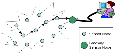
Typical multi-hop wireless sensor network architecture
Application
Area monitoring
Area monitoring is a common application of WSNs. In area monitoring, the WSN is deployed over a region where some phenomenon is to be monitored. A military example is the use of sensors detect enemy intrusion; a civilian example is the geo-fencing of gas or oil pipelines.
Health care monitoring
The sensor networks for medical applications can be of several types: implanted, wearable, and environment-embedded. The implantable medical devices are those that are inserted inside human body. Wearable devices are used on the body surface of a human or just at close proximity of the user. Environment-embedded systems employ sensors contained in the environment. Possible applications include body position measurement, location of persons, overall monitoring of ill patients in hospitals and at homes. Devices embedded in the environment track the physical state of a person for continuous health diagnosis, using as input the data from a network of depth cameras, a sensing floor, or other similar devices. Body-area networks can collect information about an individual's health, fitness, and energy expenditure. In health care applications the privacy and authenticity of user data has prime importance. Especially due to the integration of sensor networks, with IoT, the authentication of user become more challenging; however, a solution is presented in recent work.
Environmental/Earth sensing
There are many applications in monitoring environmental parameters, examples of which are given below. They share the extra challenges of harsh environments and reduced power supply.
Air pollution monitoring
Wireless sensor networks have been deployed in several cities (Stockholm, London, and Brisbane) to monitor the concentration of dangerous gases for citizens. These can take advantage of the ad hoc wireless links rather than wired installations, which also make them more mobile for testing readings in different areas.
Forest fire detection
A network of Sensor Nodes can be installed in a forest to detect when a fire has started. The nodes can be equipped with sensors to measure temperature, humidity and gases which are produced by fire in the trees or vegetation. The early detection is crucial for a successful action of the firefighters; thanks to Wireless Sensor Networks, the fire brigade will be able to know when a fire is started and how it is spreading.
Landslide detection
A landslide detection system makes use of a wireless sensor network to detect the slight movements of soil and changes in various parameters that may occur before or during a landslide. Through the data gathered it may be possible to know the impending occurrence of landslides long before it actually happens.
Water quality monitoring
Water quality monitoring involves analyzing water properties in dams, rivers, lakes and oceans, as well as underground water reserves. The use of many wireless distributed sensors enables the creation of a more accurate map of the water status, and allows the permanent deployment of monitoring stations in locations of difficult access, without the need of manual data retrieval.
Natural disaster prevention
Wireless sensor networks can effectively act to prevent the consequences of natural disasters, like floods. Wireless nodes have successfully been deployed in rivers where changes of the water levels have to be monitored in real time.
Industrial monitoring
Machine health monitoring
Wireless sensor networks have been developed for machinery condition-based maintenance (CBM) as they offer significant cost savings and enable new functionality.
Wireless sensors can be placed in locations difficult or impossible to reach with a wired system, such as rotating machinery and untethered vehicles.
Data center monitoring
Due to the high density of servers racks in a data center, often cabling and IP addresses are an issue. To overcome that problem more and more racks are fitted out with wireless temperature sensors to monitor the intake and outtake temperatures of racks. As ASHRAE recommends up to 6 temperature sensors per rack, meshed wireless temperature technology gives an advantage compared to traditional cabled sensors.
Data logging
Wireless sensor networks are also used for the collection of data for monitoring of environmental information, this can be as simple as the monitoring of the temperature in a fridge to the level of water in overflow tanks in nuclear power plants. The statistical information can then be used to show how systems have been working. The advantage of WSNs over conventional loggers is the "live" data feed that is possible.
Water/waste water monitoring
Monitoring the quality and level of water includes many activities such as checking the quality of underground or surface water and ensuring a country’s water infrastructure for the benefit of both human and animal. It may be used to protect the wastage of water.
Structural health monitoring
Structural health monitoring
Wireless sensor networks can be used to monitor the condition of civil infrastructure and related geo-physical processes close to real time, and over long periods through data logging, using appropriately interfaced sensors.
Wine production[edit]
Wireless sensor networks are used to monitor wine production, both in the field and the cellar.
Characteristics
The main characteristics of a WSN include:
- Power consumption constraints for nodes using batteries or energy harvesting. Examples of suppliers are ReVibe Energy and Perpetuum
- Ability to cope with node failures (resilience)
- Some mobility of nodes (for highly mobile nodes see MWSNs)
- Heterogeneity of nodes
- Homogeneity of nodes
- Scalability to large scale of deployment
- Ability to withstand harsh environmental conditions
- Ease of use
- Cross-layer design
Cross-layer is becoming an important studying area for wireless communications.[18] In addition, the traditional layered approach presents three main problems:
- Traditional layered approach cannot share different information among different layers, which leads to each layer not having complete information. The traditional layered approach cannot guarantee the optimization of the entire network.
- The traditional layered approach does not have the ability to adapt to the environmental change.
- Because of the interference between the different users, access conflicts, fading, and the change of environment in the wireless sensor networks, traditional layered approach for wired networks is not applicable to wireless networks.
So the cross-layer can be used to make the optimal modulation to improve the transmission performance, such as data rate, energy efficiency, QoS (Quality of Service), etc. Sensor nodes can be imagined as small computers which are extremely basic in terms of their interfaces and their components. They usually consist of a processing unit with limited computational power and limited memory, sensors or MEMS (including specific conditioning circuitry), a communication device (usually radio transceivers or alternatively optical), and a power source usually in the form of a battery. Other possible inclusions are energy harvesting modules, secondary ASICs, and possibly secondary communication interface (e.g. RS-232 or USB).
The base stations are one or more components of the WSN with much more computational, energy and communication resources. They act as a gateway between sensor nodes and the end user as they typically forward data from the WSN on to a server. Other special components in routing based networks are routers, designed to compute, calculate and distribute the routing tables.
Platforms
Hardware
sensor node
One major challenge in a WSN is to produce low cost and tiny sensor nodes. There are an increasing number of small companies producing WSN hardware and the commercial situation can be compared to home computing in the 1970s. Many of the nodes are still in the research and development stage, particularly their software. Also inherent to sensor network adoption is the use of very low power methods for radio communication and data acquisition.
In many applications, a WSN communicates with a Local Area Network or Wide Area Network through a gateway. The Gateway acts as a bridge between the WSN and the other network. This enables data to be stored and processed by devices with more resources, for example, in a remotely located server. A wireless wide area network used primarily for low-power devices is known as a Low-Power Wide-Area Network (LPWAN).
Wireless
There are several wireless standards and solutions for sensor connectivity. ZigBee can connect sensors operating at 2.4GHz with a data rate of 250Kbps. Z-wave operates at 915MHz and has a larger radio range but with a lower data rate. The IEEE 802.15.4 working group provides a standard for low power device connectivity and commonly sensors and smart meters use one of these standards for connectivity. With the emergence of Internet of Things, many other proposals have been made to provide sensor connectivity. LORA is a form of LPWAN which provides long range low power wireless connectivity for devices, which has been used in smart meters. Wi-SUN connects devices at home. NarrowBand IOT and LTE-M can connect up to millions of sensors and devices using cellular technology.
Software
Energy is the scarcest resource of WSN nodes, and it determines the lifetime of WSNs. WSNs may be deployed in large numbers in various environments, including remote and hostile regions, where ad hoc communications are a key component. For this reason, algorithms and protocols need to address the following issues:
- Increased lifespan
- Robustness and fault tolerance
- Self-configuration
Lifetime maximization: Energy/Power Consumption of the sensing device should be minimized and sensor nodes should be energy efficient since their limited energy resource determines their lifetime. To conserve power, wireless sensor nodes normally power off both the radio transmitter and the radio receiver when not in use.
Operating systems
Operating systems for wireless sensor network nodes are typically less complex than general-purpose operating systems. They more strongly resemble embedded systems, for two reasons. First, wireless sensor networks are typically deployed with a particular application in mind, rather than as a general platform. Second, a need for low costs and low power leads most wireless sensor nodes to have low-power microcontrollers ensuring that mechanisms such as virtual memory are either unnecessary or too expensive to implement.
It is therefore possible to use embedded operating systems such as eCos or uC/OS for sensor networks. However, such operating systems are often designed with real-time properties.
TinyOS is perhaps the first operating system specifically designed for wireless sensor networks. TinyOS is based on an event-driven programming model instead of multithreading. TinyOS programs are composed of event handlers and tasks with run-to-completion semantics. When an external event occurs, such as an incoming data packet or a sensor reading, TinyOS signals the appropriate event handler to handle the event. Event handlers can post tasks that are scheduled by the TinyOS kernel some time later.
LiteOS is a newly developed OS for wireless sensor networks, which provides UNIX-like abstraction and support for the C programming language.
Contiki is an OS which uses a simpler programming style in C while providing advances such as 6LoWPAN and Protothreads.
PreonVM is an OS for wireless sensor networks, which provides 6LoWPAN based on Contiki and support for the Java programming language.
Online collaborative sensor data management platforms
Online collaborative sensor data management platforms are on-line database services that allow sensor owners to register and connect their devices to feed data into an online database for storage and also allow developers to connect to the database and build their own applications based on that data. Examples include Xively and the Wikisensing platform. Such platforms simplify online collaboration between users over diverse data sets ranging from energy and environment data to that collected from transport services. Other services include allowing developers to embed real-time graphs & widgets in websites; analyse and process historical data pulled from the data feeds; send real-time alerts from any datastream to control scripts, devices and environments.
The architecture of the Wikisensing system describes the key components of such systems to include APIs and interfaces for online collaborators, a middleware containing the business logic needed for the sensor data management and processing and a storage model suitable for the efficient storage and retrieval of large volumes of data.
Simulation
At present, agent-based modeling and simulation is the only paradigm which allows the simulation of complex behavior in the environments of wireless sensors (such as flocking). Agent-based simulation of wireless sensor and ad hoc networks is a relatively new paradigm. Agent-based modelling was originally based on social simulation.
Network simulators like Opnet, Tetcos NetSim and NS can be used to simulate a wireless sensor network.
Other concepts
Security
Infrastructure-less architecture (i.e. no gateways are included, etc.) and inherent requirements (i.e. unattended working environment, etc.) of WSNs might pose several weak points that attract adversaries. Therefore, security is a big concern when WSNs are deployed for special applications such as military and healthcare. Owing to their unique characteristics, traditional security methods of computer networks would be useless (or less effective) for WSNs. Hence, lack of security mechanisms would cause intrusions towards those networks. These intrusions need to be detected and mitigation methods should be applied. More interested readers would refer to Butun et al.'s paper regarding intrusion detection systems devised for WSNs.
Distributed sensor network
If a centralized architecture is used in a sensor network and the central node fails, then the entire network will collapse, however the reliability of the sensor network can be increased by using a distributed control architecture. Distributed control is used in WSNs for the following reasons:
- Sensor nodes are prone to failure,
- For better collection of data,
- To provide nodes with backup in case of failure of the central node.
There is also no centralised body to allocate the resources and they have to be self organized.
Data integration and sensor web
The data gathered from wireless sensor networks is usually saved in the form of numerical data in a central base station. Additionally, the Open Geospatial Consortium (OGC) is specifying standards for interoperability interfaces and metadata encodings that enable real time integration of heterogeneous sensor webs into the Internet, allowing any individual to monitor or control wireless sensor networks through a web browser.
In-network processing
To reduce communication costs some algorithms remove or reduce nodes' redundant sensor information and avoid forwarding data that is of no use. As nodes can inspect the data they forward, they can measure averages or directionality for example of readings from other nodes. For example, in sensing and monitoring applications, it is generally the case that neighboring sensor nodes monitoring an environmental feature typically register similar values. This kind of data redundancy due to the spatial correlation between sensor observations inspires techniques for in-network data aggregation and mining. Aggregation reduces the amount of network traffic which helps to reduce energy consumption on sensor nodes.[30] Recently, it has been found that network gateways also play an important role in improving energy efficiency of sensor nodes by scheduling more resources for the nodes with more critical energy efficiency need and advanced energy efficient scheduling algorithms need to be implemented at network gateways for the improvement of the overall network energy efficiency.
Secure data aggregation
This is a form of in-network processing where sensor nodes are assumed to be unsecured with limited available energy, while the base station is assumed to be secure with unlimited available energy. Aggregation complicates the already existing security challenges for wireless sensor networks and requires new security techniques tailored specifically for this scenario. Providing security to aggregate data in wireless sensor networks is known as secure data aggregation in WSN. were the first few works discussing techniques for secure data aggregation in wireless sensor networks.
Two main security challenges in secure data aggregation are confidentiality and integrity of data. While encryption is traditionally used to provide end to end confidentiality in wireless sensor network, the aggregators in a secure data aggregation scenario need to decrypt the encrypted data to perform aggregation. This exposes the plaintext at the aggregators, making the data vulnerable to attacks from an adversary. Similarly an aggregator can inject false data into the aggregate and make the base station accept false data. Thus, while data aggregation improves energy efficiency of a network, it complicates the existing security challenges
XXX . 4% zero null 0 1 2 Vibrator (electronic)
In electronics before the development of switch-mode power supplies and the introduction of semiconductor devices operating off low voltage, there was a requirement to generate voltages of about 50 to 250V DC from vehicle batteries. Electromechanical components known as vibrators were used in a circuit similar to modern solid state inverter circuits to provide a pulsating DC which could be converted to a higher voltage with a transformer, rectified, and filtered to create higher-voltage DC. This "vibrator" is essentially a relay using normally closed contacts to supply power to the relay coil, thus immediately breaking the connection, only to be reconnected very quickly through the normally closed contacts. It happens so rapidly it vibrates, and sounds like a buzzer. This same rapidly pulsing contact applies the rising and falling DC voltage to the transformer which can step it up to a higher voltage.[1]
The primary use for this type of circuit was to operate vacuum tube radios in vehicles, but it also saw use with other mobile electronic devices with a 6 or 12V accumulator, especially in places with no mains electricity supply such as farms. These vibrator power supplies became popular in the 1940s, replacing more bulky motor-generator systems for the generation of AC voltages for such applications. Vacuum tubes require plate voltages ranging from about 45 volts to 250 volts in electronic devices such as radios. For portable radios, hearing aids and similar equipment, B batteries were manufactured with various voltage ratings. In order to provide the necessary voltage for a radio from the typical 6 or 12 volt DC supply available in a car or from a farm lighting battery, it was necessary to convert the steady DC supply to a pulsating DC and use a transformer to increase the voltage.
Vibrators often experienced mechanical malfunctions, being constantly in motion, such as the springs losing tension, and the contact points wearing down. As tubes began to be replaced by transistor based electrical systems, the need to generate such high voltages began to diminish. Mechanical vibrators fell out of production near the end of the 20th century, but solid-state electronic vibrators are still manufactured to be backwards compatible with older units.

Use

The vibrator was a device with switch contacts on flexible metal strips. When the vibrator was operated the strips vibrated rapidly in such a way as to make contacts presenting a 6 or 12V DC from the battery in alternating sense, rapidly exchanging positive and negative, effectively generating a square wave. Unlike DC, an alternating voltage applied to the terminals of the primary winding of a transformer will induce a different (and often higher) voltage of any desired value at the secondary; this voltage can be rectified by a thermionic diode or copper-oxide or selenium rectifier, or by an additional set of mechanical contacts making the vibrator output a synchronous rectifier. The rectified output is then filtered, ultimately converting a DC voltage to a higher one, with some losses dissipated as heat. This arrangement is an electromechanical inverter circuit. The vibrator switches used for this purpose wore out after a time, so they were usually encased in a steel or aluminum can that plugged into a socket, so they could be quickly replaced without using tools.

Active rectification
Active rectification, or synchronous rectification, is a technique for improving the efficiency of rectification by replacing diodes with actively controlled switches such as transistors, usually power MOSFETs or power BJTs. Historically, vibrator driven switches or motor-driven commutators have also been used for mechanical rectifiers and synchronous rectification.

Motivation

The constant voltage drop of a standard p-n junction diode is typically between 0.7 V and 1.7 V, causing significant power loss in the diode. Electric power depends on current and voltage: the power loss rises proportional to both current and voltage.
In low voltage converters (around 10 volts and less), the voltage drop of a diode (typically around 0.7 to 1 volt for a silicon diode at its rated current) has an adverse effect on efficiency. One classic solution replaces standard silicon diodes with Schottky diodes, which exhibit very low voltage drops (as low as 0.3 volts). However, even Schottky rectifiers can be significantly more lossy than the synchronous type, notably at high currents and low voltages.
When addressing very low-voltage converters, such as a buck converter power supply for a computer CPU (with a voltage output around 1 volt, and many amperes of output current), Schottky rectification does not provide adequate efficiency. In such applications, active rectification becomes necessary.
Description
Replacing a diode with an actively controlled switching element such as a MOSFET is the heart of active rectification. MOSFETs have a constant very low resistance when conducting, known as on-resistance (RDS(on)). They can be made with an on-resistance as low as 10 mΩ or even lower. The voltage drop across the transistor is then much lower, meaning a reduction in power loss and a gain in efficiency. However, Ohm's Law governs the voltage drop across the MOSFET, meaning that at high currents, the drop can exceed that of a diode. This limitation is usually dealt with either by placing several transistors in parallel, thereby reducing the current through each individual one, or by using a device with more active area (on FETs, a device-equivalent of parallel).
The control circuitry for active rectification usually uses comparators to sense the voltage of the input AC and open the transistors at the correct times to allow current to flow in the correct direction. The timing is very important, as a short circuit across the input power must be avoided and can easily be caused by one transistor turning on before another has turned off. Active rectifiers also clearly still need the smoothing capacitors present in passive examples.
Using active rectification to implement AC/DC conversion allows a design to undergo further improvements (with more complexity) to achieve an active power factor correction, which forces the current waveform of the AC source to follow the voltage waveform, eliminating reactive currents and allowing the total system to achieve greater efficiency.
Ideal diode
A MOSFET actively controlled to act as a rectifier—actively turned on to allow current in one direction but actively turned off to block current from flowing the other direction—is sometimes called an ideal diode. Using ideal diodes rather than a standard diodes for solar electric panel bypass, reverse-battery protection, or bridge rectifier reduces the amount of power dissipated in those diodes, improving efficiency and reducing the size of the PC board and weight of the heat sink required to deal with that power dissipation.
Such a MOSFET-based ideal diode is not to be confused with an op-amp based super diode.
SUPER DIODE
The precision rectifier, also known as a super diode, is a configuration obtained with an operational amplifier in order to have a circuit behave like an ideal diode and rectifier. It is useful for high-precision signal processing.
The op-amp-based precision rectifier should not be confused with the power MOSFET-based active rectification ideal diode.
Basic circuit

The basic circuit implementing such a feature is shown on the right, where can be any load. When the input voltage is negative, there is a negative voltage on the diode, so it works like an open circuit, no current flows through the load, and the output voltage is zero.

When the input is positive, it is amplified by the operational amplifier, which switches the diode on. Current flows through the load and, because of the feedback, the output voltage is equal to the input voltage.
The actual threshold of the super diode is very close to zero, but is not zero. It equals the actual threshold of the diode, divided by the gain of the operational amplifier.
This basic configuration has a problem, so it is not commonly used. When the input becomes (even slightly) negative, the operational amplifier runs open-loop, as there is no feedback signal through the diode. For a typical operational amplifier with high open-loop gain, the output saturates. If the input then becomes positive again, the op-amp has to get out of the saturated state before positive amplification can take place again. This change generates some ringing and takes some time, greatly reducing the frequency response of the circuit.
Improved circuit
.svg)
An alternative version is given on the right.
In this case, when the input is greater than zero, D1 is off, and D2 is on, so the output is zero because one side of is connected to the virtual ground, and there is no current through it. When the input is less than zero, D1 is on, and D2 is off, so the output is like the input with an amplification of . Its input–output relationship is the following:


This circuit has the benefit that the op-amp never goes into saturation, but its output must change by two diode voltage drops (about 1.2 V) each time the input signal crosses zero. Hence, the slew rate of the operational amplifier and its frequency response (gain–bandwidth product) will limit high-frequency performance, especially for low signal levels, although an error of less than 1% at 100 kHz is possible.
Similar circuitry can be used to create a precision full-wave rectifier circuit.
Peak detector
With a little modification, the basic precision rectifier can be used for detecting signal level peaks. In the following circuit, a capacitor retains the peak voltage level of the signal, and a switch is used for resetting the detected level. When the input Vin exceeds Vc(voltage across capacitor), the diode is forward biased and the circuit becomes voltage follower. Consequently, the output voltage Vo follows Vin as long as Vin exceeds Vc. When Vin drops below Vc, the diode becomes reverse biased and the capacitor holds the charge till input voltage again attains a value greater than Vc.

Everyday electronic devices, especially those with integrated circuits, require a reliable DC voltage source that can supply powers at all times without any hiccups. In this blog, we’ll be looking at two power supply design topologies to consider for your next project, linear regulated and switching power supplies. The power supply that you choose ultimately comes down to your requirements for efficiency, space, output regulation, transient response time, and cost.
Linear Regulated Power Supply
Linear regulators were the power supplies of choice until the 1970s for converting alternating current (AC) into a steady direct current (DC) for electronic devices. While this power supply type isn’t used as prevalently today, it’s still the best choice for applications that require minimal noise and ripple.

They might be bulky, but linear regulated power supplies are noise-free.
How They Work
The main component that allows a linear regulator to function is a steel or iron transformer. This transformer provides two functions:
- It acts as a barrier to separate high voltage AC input from low voltage DC input, which also filters out any noise getting into the output voltage.
- It reduces AC input from 115V/230V to approximately 30V which can then be converted to a steady DC voltage.
AC voltage is first lowered by the transformer and then rectified by several diodes. It’s then smoothed into a low DC voltage by a pair of large electrolytic capacitors. This low DC voltage is then regulated as a steady output voltage with the use of a transistor or integrated circuit.

Here’s a power supply with a linear regulator. (Image source)
The voltage regulator in a linear power supply acts as a variable resistor. This allows the output resistance value to change to match output power requirements. Because the voltage regulator is constantly resisting current to maintain a voltage, it also acts as a power dissipating device. This means that useful power is constantly being lost in the form of heat to keep the voltage level constant.
The transformer is already a large component to have on a printed circuit board (PCB). Because of the constant power and heat dissipation, a linear regulator power supply will require a heatsink. These two components alone add to a very heavy and bulky device when compared to the small form factor of a switching power supply.
Preferred Applications
Linear regulators are known for their poor efficiency and large size, but they do provide a noise-free output voltage. This makes them ideal for any device that requires high-frequency and low-noise, such as:
- Control circuits
- Low noise amplifiers
- Signal processors
- Automated & laboratory test equipment
- Data acquisition sensors & circuits
Advantages & Disadvantages
Linear regulated power supplies might be bulky and inefficient, but their low noise is ideal for noise-sensitive applications. Some advantages and disadvantages to consider for this topology include:
Advantages
- Simple application. Linear regulators can be implemented as an entire package and added to a circuit with only two additional filter capacitors. This makes them easy for engineers of any skill level to plan and design from scratch.
- Low cost. If your device requires a power output of less than 10W, then the component and manufacturing costs are much lower when compared to switching power supplies.
- Low noise/ripple. Linear regulators have a very low output voltage ripple and high bandwidth. This makes them ideal for any noise-sensitive applications including communication and radio devices.
Disadvantages
- Limited flexibility. Linear regulators can only be used to step down voltage. For an AC-DC power supply, a transformer with rectification and filtering will need to be placed before the linear power supply which will add to overall costs and effort.
- Limited outputs. Linear regulated power supplies only provide one output voltage. If you need more, then you’ll need to add a separate linear voltage regulator per required output.
- Poor efficiency. The average linear regulated device achieves an efficiency between 30%-60% due to heat dissipation. It also requires the addition of a heat sink which adds to the size and weight of the device.
In this day of energy efficient devices, the poor efficiency rating of a linear regulated power supply can be a deal killer. A normal linear regulated power supply will operate at about 60% efficiency for a 24V output. When you consider a 100W input, you’re looking at 40W of lost power.
Before considering using a linear regulated power supply, we highly recommend considering the power loss that you’ll get from input to output. You can quickly estimate the efficiency of a linear regulator with the following formula:

Switch Mode Power Supply (SMPS)
Switching power supplies were introduced in the 1970s and quickly became the most popular way to supply DC power to electronic devices. What makes them so great? When compared with linear regulators their high efficiency and performance stand out.

Your typical AC adapter includes a switching mode power supply.
How They Work
A switch mode power supply regulates an output voltage with pulse width modulation (PWM). This process creates high-frequency noise but it provides a high-efficiency rating in a small form factor. When plugged into an AC mains, 115V or 230VAC is first rectified and smoothed by a set of diodes and capacitors, which provides high voltage DC. This high DC voltage is then lowered using a small ferrite transformer and set of transistors. The step-down process still retains a high switching frequency between 200kHz to 500kHz.
The low DC voltage is finally converted into a steady DC output with another set of diodes, capacitors, and inductors. Any regulation required to keep the output voltage consistent is handled by adjusting the pulse width of the high-frequency waveform. This regulation process works through a feedback circuit that constantly monitors the output voltage and controls the on-off ratio of a PWM signal as needed.

Here’s a switch mode power supply with a ton more parts than linear regulated
Preferred Applications
You’ll most often find switching power supplies used in applications where battery life and temperatures are important, such as:
- Electrolysis, waste treatment, or fuel cell applications
- DC motors, slot cars, aviation, and marine applications
- R&D, manufacturing, and testing equipment
- Battery charging for Lithium-Ion batteries used in aviation and vehicles
- Electroplating, anodizing, and electroforming processes
Advantages & Disadvantages
Switching power supplies might have a higher efficiency than linear regulators, but their noise makes them a poor choice for radio and communication applications. Some advantages and disadvantages to consider for this topology include:
Advantages
- Small form factor. The step-down transformer in an SMPS operates at a high frequency which in turn reduces its volume and weight. This allows a switching power supply to enjoy a much smaller form factor than linear regulators.
- High efficiency. Voltage regulation in a switching power supply is made without dissipating excessive amounts of heat. SMPS efficiency can be as high as 85%-90%.
- Flexible applications. Additional windings can be added to a switching power supply to provide more than one output voltage. A transformer-isolated SMPS can also provide output voltages that are independent of input voltages.
Disadvantages
- Complicated design. Compared to linear regulators, planning and designing a switching power supply is typically reserved for power specialists. This is not the best power supply to choose if you plan to design your own without careful study or experience.
- High-frequency noise. The switching operation of the MOSFET within a switching power supply provides high-frequency noise in the output voltage. This often requires the use of RF shielding and EMI filters in noise-sensitive devices.
- Higher cost. For lower power outputs of 10W or less, it’s cheaper to use a linear regulated power supply.
Switch power supplies are here to stay and are the power supply of choice for applications that aren’t noise sensitive. This includes devices such as mobile phone chargers, DC motors, and more.
Linear Regulator vs. SMPS Compared
We’re now going to look at a final comparison between linear regulated and switching power supplies when compared side-by-side. Some of the most important requirements you need to consider, including size/weight, input voltage range, efficiency rating, and noise level among other factors. Here’s how it breaks down:
How to Design Your OwnIt’s beyond the scope of this blog to explain how to design a linear regulated or switch mode power supply. However, there are several guides available that we would like to share. Keep in mind that SMPS design requires a high level of complexity and is not recommended for an electronics design beginner.Linear regulated power supply design guides
- John Errington’s tutorial on power supply design
- University of Nevada, Las Vegas linear power supply design
- Instructables regulated linear DC power supply design
Switch mode power supply design guides
- 7 critical steps in switching power supply design
- ON Semi switch-mode power supply reference manual
- Electronics Tutorials switch mode power supply
Power OnMost electronic devices these days need to convert AC mains into a steady DC voltage output. There are two topologies to consider for this goal, linear regulated and switch mode power supplies. Linear regulated is ideal for applications that require low noise, whereas switching power supplies are better suited for handheld devices where battery life and efficiency is important. When deciding what topology to choose, always consider your required efficiency rating, form factor, output regulation, and noise requirements.
| Linear Regulated Power Supplies | Switch Mode Power Supplies | |
| Size | 50W linear power supply typically 3 x 5 x 5.5” | 50W switching power supply typically 3 x 5 x 1” |
| Weight | 50W linear power supply – 4lbs | 50W switching power supply – 0.62lbs |
| Input voltage range | 105 – 125 VAC and/or
210 – 250 VAC
| 90 – 132 VAC or 180 – 264 VAC without PFC
90 – 264 VAC with PFC
|
| Efficiency | Typically 40%-60% | Typically 70%-85% |
| EMI | Low | High |
| Leakage | Low | High |
| Circuit Design | Moderate complexity, can be designed with guides | High complexity, requires specialty knowledge |
| Load Regulation | 0.005% to 0.2% | 0.05% to 0.5% |
| Line Regulation | 0.005% to 0.05% | 0.05% to 0.2% |
| Part Count | Low, only requires regulator and I/O filtering | High, requires switcher, snubber, transformer, capacitors, feedback network, etc. |
XXX . XXX 4%zero5% null 0 1 2 3 4 Power Supply Design: Switch-Mode vs. Linear
DC power supplies are available in either switch-mode (also called switching) or linear designs. While both types supply DC power, the method used to produce this power is different. Depending on the application, each type of power supply has advantages over the other one. Let’s look at the differences between these two technologies as well as each design’s respective advantages and disadvantages.
A switch-mode power supply converts the AC line power directly into a DC voltage without a transformer, and this raw DC voltage is then converted into a higher frequency AC signal, which is used in the regulator circuit to produce the desired voltage and current. This results in a much smaller, lighter transformer for raising or lowering the voltage than what would be necessary at an AC line frequency of 60 Hz. These smaller transformers are also considerably more efficient than 60 Hz transformers, so the power conversion ratio is higher.
A linear power supply design applies the AC line voltage to a power transformer to raise or lower the voltage before being applied to the regulator circuitry. Since the size of the transformer is indirectly proportional to the frequency of operation, this results in a larger, heavier power supply.
Each type of power supply operation has its own set of advantages and disadvantages. A switch-mode power supply is as much as 80% smaller and lighter than a corresponding linear power supply, but it generates high-frequency noise that can interfere with sensitive electronic equipment. Unlike linear power supplies, switch-mode power supplies are able to withstand small losses of AC power in the range of 10-20 ms without affecting the outputs.
A linear power supply requires larger semiconductor devices to regulate the output voltage and therefore generates more heat, resulting in lower energy efficiency. A linear power supply normally operates around 60% efficiency for 24V outputs, whereas a switch-mode power supply operates at 80% or more. Linear power supplies have transient response times up to 100 times faster than their switch-mode counterparts, which is important in certain specialized areas.
In general, a switch-mode power supply is best suited for portable equipment, since it is lighter and more compact. Because the electrical noise is lower and easier to contain, a linear power supply is better suited for powering sensitive analog circuity.
Switch-Mode Power Supplies
Starting at $27.95
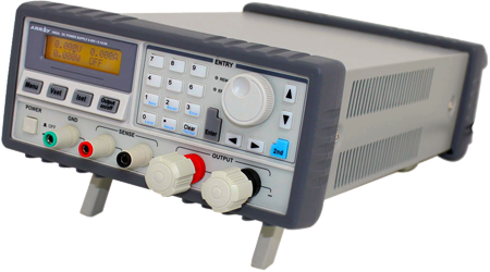
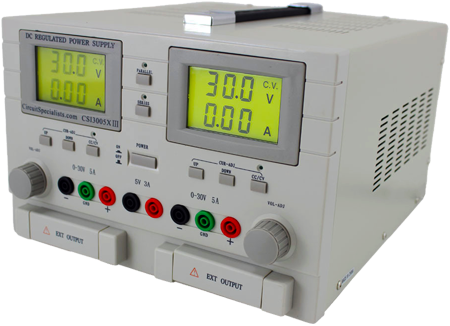
Linear Power Supplies
Starting at $49.00
Simple Switched power Supplies
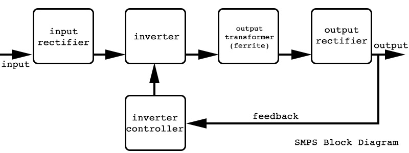
Building a simple switched power supply is easy! The schematics below were designed by Daniel. All credit goes to him. I did not test these supplies, but looking over the circuits they seem to be correct. There is little that can go wrong with the simple designs, for the more complicated ones you should double check.
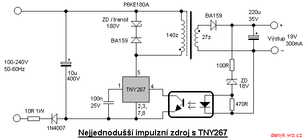
Simple SMPSS
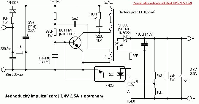

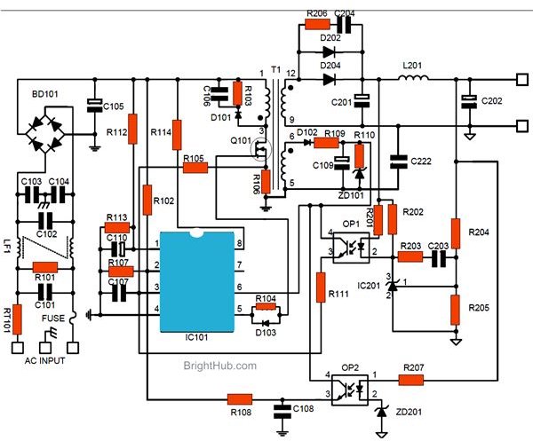
XXX . XXX . XXX Design a Switch-Mode Power Supply
Simply put, designing a power supply is a major undertaking. After making your build vs. buy decision, you face a myriad of circuit choices—more than you probably realize. Building a power supply used to be relatively straightforward, but with switch-mode methods dominating these days, it has become a complex specialty. If you’re not a power-supply expert and/or this is one of your first designs, you may need some guidance. The information presented here should help you identify your options and zero in on one to follow through with.
Step 1: A Good Specification
It all begins with a good specification. It’s critical to take the time to research your needs and write a detailed specification. As a starting point, list the following key features:
- Input-voltage (ac or dc) range
- Output voltages (dc or ac) and tolerances
- Output-current requirements
- Ripple maximum
- Estimated total power required
- Efficiency requirements, if any
- Electromagnetic-interference (EMI) considerations, if any
Step 2: A First Decision
With these specifications, you should be able to make your first big choice: linear vs. switch-mode design. Yes, linear supplies are still an option even in the current switch-mode dominant environment. If your design can accept the lower efficiency of a linear supply, you may appreciate its benefits. The major advantages of a linear supply are simplicity of design, lower cost, abundant relevant components, proven techniques, and low EMI emissions.
On the other hand, switch-mode designs are inherently noisy, and the circuits you’re powering may be susceptible to that noise. For example, an oscillator, clock, synthesizer, or other critical circuit may require low phase noise or jitter. A linear supply with a low-dropout (LDO) regulator would provide a clean dc to meet that need. At least keep the linear option in mind, as it may still be your best choice in some designs.
Most new designs are of the switch-mode variety. The advantages of a switch-mode power supply (SMPS) are just too great to ignore. Efficiency is the primary benefit, with efficiencies over 90% for many designs. Small size and reasonable cost are other benefits. The downside is complex and tricky design with many alternative approaches. You can make a more informed design choice, though, if you expand your specifications list.
Step 3: Expanded Specifications
In addition to the basic specifications compiled earlier, these should also be defined for your design:
- Requirement for electrical isolation between input and output
- Temperature range of operation
- Expected in-rush current
- Peak and average output current
- Transient exposure and response needs
- Load- and line-regulation requirements
- Switching frequency
- In addition to EMI needs, include the need for power factor correction (PFC), Underwriters Laboratories (UL), or other certifications
Step 4: Choose a Topology
The most popular dc-dc SMPS topologies are buck (a), boost (b), inverting buck-boost (c), SEPIC (d), and Zeta (e). The MOSFET does the switching, the inductors and capacitors store energy, and the diode controls the direction of current.
You may already know that several different switch-mode circuit designs are available. But did you know there are actually 16 topologies that you should be aware of? One of these is sure to fit your needs:
- Buck
- Synchronous buck
- Boost
- Inverting buck-boost
- SEPIC
- Cuk
- Zeta
- Fly-buck
- Flyback
- Two-switch flyback
- Active-clamp forward
- Single-switch forward
- Two-switch forward
- Half-bridge
- Full bridge
- Phase-shifted full bridge
Step 5: Begin Your Design
A typical approach is to narrow your choices of topology before making a final decision. The most popular topologies are buck, boost, buck-boost (and inverting version), SEPIC, and Zeta. Figure 1 shows the simplified circuits for each. The buck format steps down the input voltage while the boost steps it up. The other three can do either. The Cuk topology is a good one if you need to change the output’s polarity.
If you need some isolation, transformers can be employed. Topologies that will incorporate them in the design are flyback, clamp forward, push-pull, half bridge, or full bridge.
As for switching frequency, it usually comes down to the best estimate based on your application. Today, typical switching frequencies range from about 100 kHz to several megahertz. Low frequencies are generally better for higher-power applications requiring best efficiency. Higher frequencies make filtering easier with smaller capacitors and inductors, and can lead to reductions in both size and cost.
Also be sure to consider the impact of the fundamental and harmonics on other equipment nearby. One potential solution to limit switching EMI is dithering. That involves the random variation of the switching frequency to reduce any EMI by spreading out the spectrum over a wider range.
Switch-mode power-supply design can be a mysterious enterprise if you don’t know how or where to start. Check out this recommended blog to better understand how to select the most fitting power-supply topology for your application.
Step 6: Other Resources
Diodes and integrated circuits are at the heart of your design. Keep in mind that most semiconductor companies have support products or services, such as online design software like Texas Instruments’ WEBENCH. Don’t forget the possibility of reference designs and evaluation kits to further speed up and simplify your design.
++++++++++++++++++++++++++++++++++++++++++++++++++++++++++++++++++++++++
LINEAR AND SWITCH MODE ADAPTER

+++++++++++++++++++++++++++++++++++++++++++++++++++++++++++++++++++++++