


The cockpit is the primary interface between man and aircraft.
The cockpit equipment provides the capabilities of the aircraft
in the Air Traffic Management (ATM) system and it determines
to a large extent the safety of flight operations. We design,
develop and validate innovative aircraft and cockpit systems,
flight procedures and new cockpit and ATM concepts. We
give advice in the field of cockpit developments and the
implications for the use of the aircraft in the ATM system, the
implications for safety, efficiency and environment and the
impact on the way pilots operate. Important elements in the
cockpit are the Human Machine Interfaces (HMI) between
the pilot and the various aircraft systems. Hence, we are also
specialized in HMI development, design and tools.
Aircraft will change in the years ahead, generating challenges like:
•
More information in the cockpit. With the advent of more and im
-
proved digital data links between ground and aircraft and from
aircraft to aircraft, more and more information is flowing into the
cockpit. Where and how should this be presented?
•
More integration of information in the cockpit. The growing
amount of information must be better integrated into the cockpit
to ensure that pilot workload is kept at an acceptable level. How
can this be achieved?
•
More integration of cockpit functionality and ground systems. Air
-
craft are more and more becoming elements of a greater Air Traffic
Management System. How should pilots and air traffic controllers
communicate? And what procedures should be applied?
•
More handling of air traffic control tasks by the flight crew. How can
this be done safely?
•
More demand for silent flight. Are more silent flight operations
possible and acceptable to air crews?
•
New aircraft types and new air traffic operations. What cockpit
technology is required?
•
Human factors certification. How will new cockpits be certified for
safe use?

Cockpit
A cockpit or flight deck is the area, usually near the front of an aircraft, from which a pilot controls the aircraft. Most modern cockpits are enclosed, except on some small aircraft.

Cockpit of an Antonov An-124


Swiss HB-IZX Saab 2000 cockpit during flight

Panel of a Robin DR400

1936 de Havilland Hornet Moth cockpit
Etymology
The word cockpit was originally a sailing term for the coxswain's station in a Royal Navy ship, and later the location of the ship's rudder controls.[citation needed] Cockpit first appeared in the English language in the 1580s, "a pit for fighting cocks", from cock + pit. Used in nautical sense (1706) for midshipmen's compartment below decks; transferred to airplanes (1914) and to cars (1930s).[2] From about 1935,[citation needed] cockpit came to be used informally to refer to the driver's seat of a car, especially a high performance one, and this is official terminology in Formula One.In an airliner, the cockpit is usually referred to as the flight deck, the term deriving from its use by the RAF for the separate, upper platform in large flying boats where the pilot and co-pilot sat. In the US and many other countries, however, the term cockpit is also used for airliners.[citation needed]
Ergonomics
The first airplane with an enclosed cabin appeared in 1912 on the Avro Type F; however, during the early 1920s there were many passenger aircraft in which the crew remained open to the air while the passengers sat in a cabin. Military biplanes and the first single-engined fighters and attack aircraft also had open cockpits, some as late as the Second World War when enclosed cockpits became the norm.The largest impediment to having closed cabins was the material the windows were to be made of. Prior to Perspex becoming available in 1933, windows were either safety glass, which was heavy, or cellulose nitrate (i.e.: guncotton), which yellowed quickly and was extremely flammable. In the mid-1920s many aircraft manufacturers began using enclosed cockpits for the first time. Early airplanes with closed cockpits include the 1924 Fokker F.VII, the 1926 German Junkers W 34 transport, the 1926 Ford Trimotor, the 1927 Lockheed Vega, the Spirit of St. Louis and the passenger aircraft manufactured by the Douglas and Boeing companies during the mid-1930s. Open-cockpit airplanes were almost extinct by the mid-1950s, with the exception of training planes, crop-dusters and homebuilt aircraft designs.
Cockpit windows may be equipped with a sun shield. Most cockpits have windows that can be opened when the aircraft is on the ground. Nearly all glass windows in large aircraft have an anti-reflective coating, and an internal heating element to melt ice. Smaller aircraft may be equipped with a transparent aircraft canopy.
In most cockpits the pilot's control column or joystick is located centrally (centre stick), although in some military fast jets the side-stick is located on the right hand side. In some commercial airliners (i.e.: Airbus—which features the glass cockpit concept) both pilots use a side-stick located on the outboard side, so Captain's side-stick on the left and First-officer's seat on the right.
Except for some helicopters, the right seat in the cockpit of an aircraft is the seat used by the co-pilot. The captain or pilot in command sits in the left seat, so that he can operate the throttles and other pedestal instruments with his right hand. The tradition has been maintained to this day, with the co-pilot on the right hand side.
The layout of the cockpit, especially in the military fast jet, has undergone standardisation, both within and between aircraft different manufacturers and even different nations. One of the most important developments was the "Basic Six" pattern, later the "Basic T", developed from 1937 onwards by the Royal Air Force, designed to optimise pilot instrument scanning.
Ergonomics and Human Factors concerns are important in the design of modern cockpits. The layout and function of cockpit displays controls are designed to increase pilot situation awareness without causing information overload. In the past, many cockpits, especially in fighter aircraft, limited the size of the pilots that could fit into them. Now, cockpits are being designed to accommodate from the 1st percentile female physical size and the 99th percentile male size.
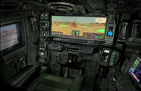
In the design of the cockpit in a military fast jet, the traditional "knobs and dials" associated with the cockpit are mainly absent. Instrument panels are now almost wholly replaced by electronic displays, which are themselves often re-configurable to save space. While some hard-wired dedicated switches must still be used for reasons of integrity and safety, many traditional controls are replaced by multi-function re-configurable controls or so-called "soft keys". Controls are incorporated onto the stick and throttle to enable the pilot to maintain a head-up and eyes-out position – the so-called Hands On Throttle And Stick or HOTAS concept,. These controls may be then further augmented by new control media such as head pointing with a Helmet Mounted Sighting System or Direct voice input (DVI). New advances in auditory displays even allow for Direct Voice Output of aircraft status information and for the spatial localisation of warning sounds for improved monitoring of aircraft systems.
The layout of control panels in modern airliners has become largely unified across the industry. The majority of the systems-related controls (such as electrical, fuel, hydraulics and pressurization) for example, are usually located in the ceiling on an overhead panel. Radios are generally placed on a panel between the pilot's seats known as the pedestal. Automatic flight controls such as the autopilot are usually placed just below the windscreen and above the main instrument panel on the glareshield. A central concept in the design of the cockpit is the Design Eye Position or "DEP", from which point all displays should be visible.
Most modern cockpits will also include some kind of integrated warning system.
In a 2013 comparative study of a number of novel methods for cockpit-user interaction, touchscreen produced the largest number of "best scores".
Flight instruments


Vickers VC-10 cockpit of the 1960s

A later analogue cockpit (1970s) of a Hawker Siddeley Trident airliner
MCP
A mode control panel, usually a long narrow panel located centrally in front of the pilot, may be used to control heading, speed, altitude, vertical speed, vertical navigation and lateral navigation. It may also be used to engage or disengage both the autopilot and the autothrottle. The panel as an area is usually referred to as the "glareshield panel". MCP is a Boeing designation (that has been informally adopted as a generic name for the unit/panel) for a unit that allows for the selection and parameter setting of the different autoflight functions, the same unit on an Airbus aircraft is referred to as the FCU (Flight Control unit).PFD
The primary flight display is usually located in a prominent position, either centrally or on either side of the cockpit. It will in most cases include a digitized presentation of the attitude indicator, air speed and altitude indicators (usually as a tape display) and the vertical speed indicator. It will in many cases include some form of heading indicator and ILS/VOR deviation indicators. In many cases an indicator of the engaged and armed autoflight system modes will be present along with some form of indication of the selected values for altitude, speed, vertical speed and heading. It may be pilot selectable to swap with the ND.ND
A navigation display, which may be adjacent to the PFD, shows the current route and information on the next waypoint, current wind speed and wind direction. It may be pilot selectable to swap with the PFD.EICAS/ECAM
The Engine Indication and Crew Alerting System (used for Boeing) or Electronic Centralized Aircraft Monitor (for Airbus) will allow the pilot to monitor the following information: values for N1, N2 and N3, fuel temperature, fuel flow, the electrical system, cockpit or cabin temperature and pressure, control surfaces and so on. The pilot may select display of information by means of button press.FMS
The flight management system/control unit may be used by the pilot to enter and check for the following information: flight plan, speed control, navigation control, and so on.Back-up instruments
In a less prominent part of the cockpit, in case of failure of the other instruments, there will be a battery-powered integrated standby instrument system along with a magnetic compass, showing essential flight information such as speed, altitude, attitude and heading.Aerospace industry technologies
In the U.S. the Federal Aviation Administration (FAA) and the National Aeronautics and Space Administration (NASA) have researched the ergonomic aspects of cockpit design and have conducted investigations of airline industry accidents. Cockpit design disciplines include Cognitive science, Neuroscience, Human–computer interaction, Human Factors Engineering, Anthropometry and Ergonomics.Aircraft designs have adopted the fully digital "glass cockpit". In such designs, instruments and gauges, including navigational map displays, use a user interface markup language known as ARINC 661. This standard defines the interface between an independent cockpit display system, generally produced by a single manufacturer, and the avionics equipment and user applications it is required to support, by means of displays and controls, often made by different manufacturers. The separation between the overall display system, and the applications driving it, allows for considerable specialization and independence.
Electronic flight instrument system
An electronic flight instrument system (EFIS) is a flight deck instrument display system in which the display technology used is electronic rather than electromechanical. EFIS normally consists of a primary flight display (PFD), multi-function display (MFD) and engine indicating and crew alerting system (EICAS) display. Although cathode ray tube (CRT) displays were used at first, liquid crystal displays (LCD) are now more common.The complex electromechanical attitude director indicator (ADI) and horizontal situation indicator (HSI) were the first candidates for replacement by EFIS. However, there are now few flight deck instruments for which no electronic display is available.
EFIS installations vary greatly. A light aircraft might be equipped with one display unit, on which flight and navigation data are displayed. A wide-body aircraft is likely to have six or more display units.
Typical EFIS displays and controls can be seen at this B737 technical information web site. The equivalent electromechanical instruments are also shown here.
An EFIS installation will follow the sequence:
- Displays
- Controls
- Data processors
Display units
Primary flight display (PFD)
On the flight deck, the display units are the most obvious parts of an EFIS system, and are the features which give rise to the name "glass cockpit". The display unit taking the place of the ADI is called the primary flight display (PFD). If a separate display replaces the HSI, it is called the navigation display. The PFD displays all information critical to flight, including calibrated airspeed, altitude, heading, attitude, vertical speed and yaw. The PFD is designed to improve a pilot's situational awareness by integrating this information into a single display instead of six different analog instruments, reducing the amount of time necessary to monitor the instruments. PFDs also increase situational awareness by alerting the aircrew to unusual or potentially hazardous conditions — for example, low airspeed, high rate of descent — by changing the color or shape of the display or by providing audio alerts.The names Electronic Attitude Director Indicator and Electronic Horizontal Situation Indicator are used by some manufacturers. However, a simulated ADI is only the centerpiece of the PFD. Additional information is both superimposed on and arranged around this graphic.
Multi-function displays can render a separate navigation display unnecessary. Another option is to use one large screen to show both the PFD and navigation display.
The PFD and navigation display (and multi-function display, where fitted) are often physically identical. The information displayed is determined by the system interfaces where the display units are fitted. Thus, spares holding is simplified: the one display unit can be fitted in any position.
LCD units generate less heat than CRTs; an advantage in a congested instrument panel. They are also lighter, and occupy a lower volume.
Multi-function display (MFD)

The Navigation Display (ND) of a Boeing 737NG Aircraft.
MFDs can also display information about aircraft systems, such as fuel and electrical systems (see EICAS, below). As with the PFD, the MFD can change the color or shape of the data to alert the aircrew to hazardous situations..
Engine indications and crew alerting system (EICAS) / electronic centralized aircraft monitoring (ECAM)
EICAS (Engine Indications and Crew Alerting System) displays information about the aircraft's systems, including its fuel, electrical and propulsion systems (engines). EICAS displays are often designed to mimic traditional round gauges while also supplying digital readouts of the parameters.EICAS improves situational awareness by allowing the aircrew to view complex information in a graphical format and also by alerting the crew to unusual or hazardous situations. For example, if an engine begins to lose oil pressure, the EICAS might sound an alert, switch the display to the page with the oil system information and outline the low oil pressure data with a red box. Unlike traditional round gauges, many levels of warnings and alarms can be set. Proper care must be taken when designing EICAS to ensure that the aircrew are always provided with the most important information and not overloaded with warnings or alarms.
ECAM is a similar system used by Airbus, which in addition to providing EICAS functions also recommend remedial action.

A 737NG EICAS after landing, showing outside air temperature, N1 RPM,
exhaust gas temperature, N2 RPM, Fuel Flow/Fuel Used indications, fuel
on the tanks, oil pressure, oil temperature, oil quantity, engine
vibration, hydraulic pressure and hydraulic quantity.
Control panels
The pilots are provided with controls, with which they select display range and mode (for example, map or compass rose) and enter data (such as selected heading).Where inputs by the pilot are used by other equipment, data buses broadcast the pilot's selections so that the pilot only needs to enter the selection once. For example, the pilot selects the desired level-off altitude on a control unit. The EFIS repeats this selected altitude on the PFD and by comparing it with the actual altitude (from the air data computer) generates an altitude error display. This same altitude selection is used by the automatic flight control system to level off, and by the altitude alerting system to provide appropriate warnings.
Data processors
The EFIS visual display is produced by the symbol generator. This receives data inputs from the pilot, signals from sensors, and EFIS format selections made by the pilot. The symbol generator can go by other names, such as display processing computer, display electronics unit, etc.The symbol generator does more than generate symbols. It has (at the least) monitoring facilities, a graphics generator and a display driver. Inputs from sensors and controls arrive via data buses, and are checked for validity. The required computations are performed, and the graphics generator and display driver produce the inputs to the display units.
Monitoring
Like personal computers, flight instrument systems need power-on-self-test facilities and continuous self-monitoring. Flight instrument systems, however, need additional monitoring capabilities:- Input validation — verify that each sensor is providing valid data
- Data comparison — cross check inputs from duplicated sensors
- Display monitoring — detect failures within the instrument system
Former practice
Traditional (electromechanical) displays were equipped with synchro mechanisms which would transmit, to an instrument comparator, the pitch, roll and heading that were actually being shown on the Captain's and First Officer's instruments. The comparator warned of excessive differences between the Captain and First Officer displays. Even a fault as far downstream as a jam in, say, the roll mechanism of an ADI would trigger a comparator warning.The instrument comparator thus provided both comparator monitoring and display monitoring.
Comparator monitoring
With EFIS, the comparator function is as simple as ever. Is the roll data (bank angle) from sensor 1 the same as the roll data from sensor 2? If not, put a warning caption (such as CHECK ROLL) on both PFDs. Comparison monitors will give warnings for airspeeds, pitch, roll and altitude indications. The more advanced EFIS systems, more comparator monitors will be enabled.Display monitoring
An EFIS display allows no easy re-transmission of what is shown on the display. What is required is a new approach to display monitoring that provides safety equivalent to that of the traditional system. One solution is to keep the display unit as simple as possible, so that it is unable to introduce errors. The display unit either works or does not work. A failure is always obvious, never insidious. Now the monitoring function can be shifted upstream to the output of the symbol generator.In this technique, each symbol generator contains two display monitoring channels. One channel, the internal, samples the output from its own symbol generator to the display unit and computes, for example, what roll attitude should produce that indication. This computed roll attitude is then compared with the roll attitude input to the symbol generator from the INS or AHRS. Any difference has probably been introduced by faulty processing, and triggers a warning on the relevant display.
The external monitoring channel carries out the same check on the symbol generator on the other side of the flight deck: the Captain's symbol generator checks the First Officer's, the First Officer's checks the Captain's. Whichever symbol generator detects a fault, puts up a warning on its own display.
The external monitoring channel also checks sensor inputs (to the symbol generator) for reasonableness. A spurious input, such as a radio height greater than the radio altimeter's maximum, results in a warning.
Human factors
Clutter
At various stages of a flight, a pilot uses different combinations of data. Ideally, only the data in use would be displayed, but an electromechanical instrument has to be in view all the time. To improve display clarity, intricate mechanisms are used on ADIs and HSIs to remove superfluous indications temporarily, e.g., removing the glide slope scale when it is not being used.With EFIS, some indications, e.g., engine vibration, might not be displayed under normal conditions. If limits are exceeded, then the reading will be displayed. In similar fashion, EFIS is programmed to show the glideslope scale and pointer only during an ILS approach.
If a failure of input data is detected, electromechanical instruments add yet another indicator to the display. Typically, a bar is dropped across the erroneous data. EFIS, on the other hand, removes invalid data from the display and substitutes an appropriate warning.
A de-clutter mode is activated automatically when the pilot's attention is required to be focused on a specific item. For example, if the aircraft is pitched up or down above a specified pitch, usually 30 to 60 degrees, the attitude indicator will de-clutter items from sight until the pitch is brought to an acceptable level. This allows the pilot to focus on the most important matter of aircraft control.
Colour
Although colour has long been used in traditional instruments, it is restricted to aiding in identification of the data. There is no means of changing the color of any display component.This restriction has been lifted with EFIS. For example, as an aircraft approaches the glideslope, a blue caption could indicate glide slope is armed; on capture the color might change to green.
On a typical EFIS system, the navigation needles are color-coded to reflect the type of navigation being used. Green needles are used for ground based navigation such as VORs, Localizers and ILS systems. Magenta needles are used for GPS navigation.
Advantages
EFIS offers versatility by avoiding some of the physical limitations of traditional instruments. Thus, the same display which shows a course deviation indicator, can be switched to show the planned track provided by an area navigation or flight management system. If desired, the weather radar picture can then be superimposed on the displayed route.The flexibility afforded by software modifications, minimises costs when new aircraft equipment and new regulations are introduced. The EFIS system can be updated with new software to extend its capabilities. Such updates introduced in the 1990s included ground proximity warning system and traffic collision avoidance system.
A degree of redundancy is available even with the simple two-screen EFIS installation. Should the PFD fail, transfer switching repositions its vital information to the screen normally occupied by the navigation display.
Advances in EFIS
In the late 1980s, EFIS became standard equipment on most Boeing and Airbus airliners, and many business aircraft adopted EFIS in the 1990s.Recent advances in computing power and reductions in the cost of liquid-crystal displays and navigational sensors (such as GPS and attitude and heading reference system) have brought EFIS to general aviation aircraft. Notable examples are the Garmin G1000 and Chelton Flight Systems EFIS-SV.
Several EFIS manufacturers have focused on the experimental aircraft market, producing EFIS and EICAS systems for as little as US$1,000. The low cost is possible for several reasons, including steep drops in sensor prices and a lack of requirements to receive Federal Aviation Administration certification. This latter point restricts their use to experimental aircraft and certain other aircraft categories depending on local regulations. Uncertified EFIS systems are also found in Sport Pilot category aircraft, including factory built, microlight and ultralight aircraft. These systems can be fitted to certified aircraft in some cases as secondary or backup systems depending on local aviation authorities rules and regulations.
Fixed-wing aircraft
A fixed-wing aircraft is an aircraft, such as an aeroplane, which is capable of flight using wings that generate lift caused by the vehicle's forward airspeed and the shape of the wings. Fixed-wing aircraft are distinct from rotary-wing aircraft, in which the wings form a rotor mounted on a spinning shaft, and ornithopters, in which the wings flap in similar manner to a bird.Glider fixed-wing aircraft, including free-flying gliders of various kinds and tethered kites, can use moving air to gain height. Powered fixed-wing aircraft that gain forward thrust from an engine (aeroplanes) include powered paragliders, powered hang gliders and some ground effect vehicles.
The wings of a fixed-wing aircraft are not necessarily rigid; kites, hang-gliders, variable-sweep wing aircraft and aeroplanes using wing-warping are all fixed-wing aircraft. Most fixed-wing aircraft are flown by a pilot on board the aircraft, but some are designed to be remotely or computer-controlled.
History
Main articles: Aviation history and Early flying machines
Early kites
Kites were used approximately 2,800 years ago in China, where materials ideal for kite building were readily available. Some authors hold that leaf kites were being flown much earlier in what is now Indonesia, based on their interpretation of cave paintings on Muna Island off Sulawesi. By at least 549 AD paper kites were being flown, as it was recorded in that year a paper kite was used as a message for a rescue mission. Ancient and medieval Chinese sources list other uses of kites for measuring distances, testing the wind, lifting men, signaling, and communication for military operations.
Boys flying a kite in 1828 Bavaria, by Johann Michael Voltz
Gliders and powered models
Around 400 BC in Greece, Archytas was reputed to have designed and built the first artificial, self-propelled flying device, a bird-shaped model propelled by a jet of what was probably steam, said to have flown some 200 m (660 ft). This machine may have been suspended for its flight.Some of the earliest recorded attempts with gliders were those by the 9th-century poet Abbas Ibn Firnas and the 11th-century monk Eilmer of Malmesbury; both experiments injured their pilots.

In the 1890s, Lawrence Hargrave conducted research on wing structures and developed a box kite that lifted the weight of a man. His box kite designs were widely adopted. Although he also developed a type of rotary aircraft engine, he did not create and fly a powered fixed-wing aircraft.
Powered flight
See also: Aviation in the pioneer era
Sir Hiram Maxim
built a craft that weighed 3.5 tons, with a 110-foot (34-meter)
wingspan that was powered by two 360-horsepower (270-kW) steam engines
driving two propellers. In 1894, his machine was tested with overhead
rails to prevent it from rising. The test showed that it had enough lift
to take off. The craft was uncontrollable, which Maxim, it is presumed,
realized, because he subsequently abandoned work on it.
Wright Flyer III piloted by Orville Wright over Huffman Prairie, 4 October 1905

Santos-Dumont's self-propelled 14-bis on an old postcard
The Bleriot VIII design of 1908 was an early aircraft design that had the modern monoplane tractor configuration. It had movable tail surfaces controlling both yaw and pitch, a form of roll control supplied either by wing warping or by ailerons and controlled by its pilot with a joystick and rudder bar. It was an important predecessor of his later Bleriot XI Channel-crossing aircraft of the summer of 1909.

Curtiss NC-4 flying boat after it completed the first crossing of the Atlantic by a fixed-wing heavier-than-air aircraft in 1919.
World War I
World War I served as a testbed for the use of the aircraft as a weapon. Initially seen by the generals as a "toy", aircraft demonstrated their potential as mobile observation platforms, then proved themselves to be machines of war capable of causing casualties to the enemy. The earliest known aerial victory with a synchronised machine gun-armed fighter aircraft occurred in 1915, by German Luftstreitkräfte Leutnant Kurt Wintgens. Fighter aces appeared; the greatest (by number of air victories) was Manfred von Richthofen.Following WWI, aircraft technology continued to develop. Alcock and Brown crossed the Atlantic non-stop for the first time in 1919. The first commercial flights took place between the United States and Canada in 1919.
World War II
Aeroplanes had a presence in all the major battles of World War II. They were an essential component of the military strategies of the period, such as the German Blitzkrieg or the American and Japanese aircraft carrier campaigns of the Pacific.Military gliders were developed and used in several campaigns, but they did not become widely used due to the high casualty rate often encountered. The Focke-Achgelis Fa 330 Bachstelze (Wagtail) rotor kite of 1942 was notable for its use by German submarines.
Before and during the war, both British and German designers were developing jet engines to power aeroplanes. The first jet aircraft to fly, in 1939, was the German Heinkel He 178. In 1943 the first operational jet fighter, the Messerschmitt Me 262, went into service with the German Luftwaffe and later in the war the British Gloster Meteor entered service but never saw action — top airspeeds of aircraft for that era went as high as 1,130 km/h (702 mph), with the early July 1944 unofficial record flight of the German Me 163B V18 rocket fighter prototype.
Postwar
In October 1947, the Bell X-1 was the first aircraft to exceed the speed of sound.In 1948–49, aircraft transported supplies during the Berlin Blockade. New aircraft types, such as the B-52, were produced during the Cold War.
The first jet airliner, the de Havilland Comet, was introduced in 1952, followed by the Soviet Tupolev Tu-104 in 1956. The Boeing 707, the first widely successful commercial jet, was in commercial service for more than 50 years, from 1958 to 2010. The Boeing 747 was the world's biggest passenger aircraft from 1970 until it was surpassed by the Airbus A380 in 2005.
Classes of fixed-wing aircraft
Airplane/aeroplane
Main article: Airplane
An aeroplane (also known as an airplane or simply a plane) is a powered fixed-wing aircraft that is propelled forward by thrust from a jet engine or propeller.
Planes come in a variety of sizes, shapes, and wing configurations. The
broad spectrum of uses for planes includes recreation, transportation
of goods and people, military, and research.Seaplane
Main article: Seaplane
A seaplane is a fixed-wing aircraft capable of taking off and landing (alighting) on water. Seaplanes that can also operate from dry land are a subclass called amphibian aircraft. These aircraft were sometimes called hydroplanes. Seaplanes and amphibians are usually divided into two categories based on their technological characteristics: floatplanes and flying boats.- A floatplane is similar in overall design to a land-based aeroplane, with a generally unmodified fuselage from as compared to its landplane version, except that the wheels at the base of the undercarriage are replaced by floats, allowing the craft to operate from water rather than from dry land.
- A flying boat is a seaplane with a watertight hull forming the lower (ventral) areas of its fuselage, resting directly on the water's surface. It differs from a float plane as it does not need additional floats for buoyancy, although it may have small underwing floats or fuselage-mount sponsons to stabilize it on the water. Large seaplanes are usually flying boats, with most classic amphibian aircraft designs using some form of flying-boat design for their fuselage/hull.
Powered gliders
Many forms of glider (see below) may be modified by adding a small power plant. These include:- Motor glider - a conventional glider or sailplane with an auxiliary power plant that may be used when in flight to increase performance.
- Powered hang glider - a hang glider with a power plant added.
- Powered parachute - a paraglider type of parachute with an integrated airframe, seat, undercarriage and power plant hung beneath.
- Powered paraglider or paramotor - a paraglider with a power plant suspended behind the pilot.
Ground effect vehicle
Main article: Ground effect vehicle
A ground effect vehicle (GEV) is a craft that attains level flight near the surface of the earth, making use of the ground effect
- an aerodynamic interaction between the wings and the earth's surface.
Some GEVs are able to fly higher out of ground effect (OGE) when
required - these are classed as powered fixed-wing aircraft.Glider

A glider (sailplane) being winch-launched
Main article: Glider (aircraft)
A glider is a heavier-than-air craft that is supported in
flight by the dynamic reaction of the air against its lifting surfaces,
and whose free flight does not depend on an engine. A sailplane is a fixed-wing glider designed for soaring - the ability to gain height in updrafts of air and to fly for long periods.Gliders are mainly used for recreation, but have also been used for other purposes such as aerodynamics research, warfare and recovering spacecraft.
A motor glider does have an engine for extending its performance and some have engines powerful enough to take off, but the engine is not used in normal flight.
As is the case with planes, there are a wide variety of glider types differing in the construction of their wings, aerodynamic efficiency, location of the pilot and controls. Perhaps the most familiar type is the toy paper plane.
Large gliders are most commonly launched by a tow-plane or by a winch. Military gliders have been used in war to deliver assault troops, and specialised gliders have been used in atmospheric and aerodynamic research. Rocket-powered aircraft and spaceplanes have also made unpowered landings.
Gliders and sailplanes that are used for the sport of gliding have high aerodynamic efficiency. The highest lift-to-drag ratio is 70:1, though 50:1 is more common. After launch, further energy is obtained through the skillful exploitation of rising air in the atmosphere. Flights of thousands of kilometres at average speeds over 200 km/h have been achieved.
The most numerous unpowered aircraft are paper aeroplanes, a handmade type of glider. Like hang gliders and paragliders, they are foot-launched and are in general slower, smaller, and less expensive than sailplanes. Hang gliders most often have flexible wings given shape by a frame, though some have rigid wings. Paragliders and paper aeroplanes have no frames in their wings.
Gliders and sailplanes can share a number of features in common with powered aircraft, including many of the same types of fuselage and wing structures. For example, the Horten H.IV was a tailless flying wing glider, and the delta wing-shaped Space Shuttle orbiter flew much like a conventional glider in the lower atmosphere. Many gliders also use similar controls and instruments as powered craft.
Types of glider
The main application today of glider aircraft is sport and recreation.
Sailplane
Main article: Glider (sailplane)
Gliders were developed from the 1920s for recreational purposes. As pilots began to understand how to use rising air, sailplane gliders were developed with a high lift-to-drag ratio. These allowed longer glides to the next source of 'lift', and so increase their chances of flying long distances. This gave rise to the popular sport of gliding.Early gliders were mainly built of wood and metal but the majority of sailplanes now use composite materials incorporating glass, carbon or aramid fibres. To minimise drag, these types have a streamlined fuselage and long narrow wings having a high aspect ratio. Both single-seat and two-seat gliders are available.
Initially training was done by short 'hops' in primary gliders which are very basic aircraft with no cockpit and minimal instruments. Since shortly after World War II training has always been done in two-seat dual control gliders, but high performance two-seaters are also used to share the workload and the enjoyment of long flights. Originally skids were used for landing, but the majority now land on wheels, often retractable. Some gliders, known as motor gliders, are designed for unpowered flight, but can deploy piston, rotary, jet or electric engines. Gliders are classified by the FAI for competitions into glider competition classes mainly on the basis of span and flaps.

Ultralight "airchair" Goat 1 glider
Military gliders

A Waco CG-4A of the USAAF in 1943
Research gliders
Even after the development of powered aircraft, gliders continued to be used for aviation research. The NASA Paresev Rogallo flexible wing was originally developed to investigate alternative methods of recovering spacecraft. Although this application was abandoned, publicity inspired hobbyists to adapt the flexible-wing airfoil for modern hang gliders.Initial research into many types of fixed-wing craft, including flying wings and lifting bodies was also carried out using unpowered prototypes.
Hang glider

Hang gliding
Paraglider
A paraglider is a lightweight, free-flying, foot-launched glider aircraft with no rigid primary structure. The pilot sits in a harness suspended below a hollow fabric wing whose shape is formed by its suspension lines, the pressure of air entering vents in the front of the wing and the aerodynamic forces of the air flowing over the outside. Paragliding is most often a recreational activity.Unmanned gliders
A paper plane is a toy aircraft (usually a glider) made out of paper or paperboard.Model glider aircraft are models of aircraft using lightweight materials such as polystyrene and balsa wood. Designs range from simple glider aircraft to accurate scale models, some of which can be very large.
Glide bombs are bombs with aerodynamic surfaces to allow a gliding flightpath rather than a ballistic one. This enables the carrying aircraft to attack a heavily defended target from a distance.
Kite

A kite in flight
Main article: Kite
A kite is an aircraft tethered to a fixed point so that the wind blows over its wings.[26] Lift
is generated when air flows over the kite's wing, producing low
pressure above the wing and high pressure below it, and deflecting the
airflow downwards. This deflection also generates horizontal drag
in the direction of the wind. The resultant force vector from the lift
and drag force components is opposed by the tension of the one or more
rope lines or tethers attached to the wing.Kites are mostly flown for recreational purposes, but have many other uses. Early pioneers such as the Wright Brothers and J.W. Dunne sometimes flew an aircraft as a kite in order to develop it and confirm its flight characteristics, before adding an engine and flight controls, and flying it as an aeroplane.
See also: Rotor kite
Uses

Chinese dragon kite more than one hundred feet long which flew in the Berkeley, California, kite festival in 2000
Military applications
Kites have been used for signaling, for delivery of munitions, and for observation, by lifting an observer above the field of battle, and by using kite aerial photography.Science and meteorology
Kites have been used for scientific purposes, such as Benjamin Franklin's famous experiment proving that lightning is electricity. Kites were the precursors to the traditional aircraft, and were instrumental in the development of early flying craft. Alexander Graham Bell experimented with very large man-lifting kites, as did the Wright brothers and Lawrence Hargrave. Kites had a historical role in lifting scientific instruments to measure atmospheric conditions for weather forecasting.Radio aerials and light beacons
Kites can be used to carry radio antennas. This method was used for the reception station of the first transatlantic transmission by Marconi. Captive balloons may be more convenient for such experiments, because kite-carried antennas require a lot of wind, which may be not always possible with heavy equipment and a ground conductor.Kites can be used to carry light effects such as lightsticks or battery powered lights.
Kite traction

A quad-line traction kite, commonly used as a power source for kite surfing
Kite sailing opens several possibilities not available in traditional sailing:
- Wind speeds are greater at higher altitudes
- Kites may be manoeuvered dynamically which increases the force available dramatically
- There is no need for mechanical structures to withstand bending forces; vehicles or hulls can be very light or dispensed with all together
Power generation
See also: laddermill and High altitude wind power
Conceptual research and development projects by over a hundred
entities are investigating the use of kites in harnessing high altitude
wind currents to generate electricity.Cultural uses
Kite festivals are a popular form of entertainment throughout the world. They include local events, traditional festivals and major international festivals.Airframe
Main article: Airframe
The structural parts of a fixed-wing aircraft are called the
airframe. The parts present can vary according to the aircraft's type
and purpose. Early types were usually made of wood with fabric wing
surfaces, When engines became available for powered flight around a
hundred years ago, their mounts were made of metal. Then as speeds
increased more and more parts became metal until by the end of WWII
all-metal aircraft were common. In modern times, increasing use of composite materials has been made.Typical structural parts include:
- One or more large horizontal wings, often with an airfoil cross-section shape. The wing deflects air downward as the aircraft moves forward, generating lifting force to support it in flight. The wing also provides stability in roll to stop the aircraft from rolling to the left or right in steady flight.

The An-225 Mriya, which can carry a 250-tonne payload, has two vertical stabilisers.
- A fuselage, a long, thin body, usually with tapered or rounded ends to make its shape aerodynamically smooth. The fuselage joins the other parts of the airframe and usually contains important things such as the pilot, payload and flight systems.
- A vertical stabiliser or fin is a vertical wing-like surface mounted at the rear of the plane and typically protruding above it. The fin stabilises the plane's yaw (turn left or right) and mounts the rudder which controls its rotation along that axis.
- A horizontal stabiliser, usually mounted at the tail near the vertical stabilizer. The horizontal stabilizer is used to stabilise the plane's pitch (tilt up or down) and mounts the elevators which provide pitch control.
- Landing gear, a set of wheels, skids, or floats that support the plane while it is on the surface. On seaplanes the bottom of the fuselage or floats (pontoons) support it while on the water. On some planes the landing gear retracts during flight to reduce drag.
Wings
The wings of a fixed-wing aircraft are static planes extending either side of the aircraft. When the aircraft travels forwards, air flows over the wings which are shaped to create lift.Wing structure
Kites and some light weight gliders and aeroplanes have flexible wing surfaces which are stretched across a frame and made rigid by the lift forces exerted by the airflow over them. Larger aircraft have rigid wing surfaces which provide additional strength.Whether flexible or rigid, most wings have a strong frame to give them their shape and to transfer lift from the wing surface to the rest of the aircraft. The main structural elements are one or more spars running from root to tip, and many ribs running from the leading (front) to the trailing (rear) edge.
Early aeroplane engines had little power and light weight was very important. Also, early aerofoil sections were very thin, and could not have strong frame installed within. So until the 1930s most wings were too light weight to have enough strength and external bracing struts and wires were added. When the available engine power increased during the 1920s and 1930s, wings could be made heavy and strong enough that bracing was not needed any more. This type of unbraced wing is called a cantilever wing.
Wing configuration
Main articles: Wing configuration and Wing

Captured Morane-Saulnier L wire-braced parasol monoplane
A monoplane has a single wing plane, a biplane has two stacked one above the other, a tandem wing has two placed one behind the other. When the available engine power increased during the 1920s and 1930s and bracing was no longer needed, the unbraced or cantilever monoplane became the most common form of powered type.
The wing planform is the shape when seen from above. To be aerodynamically efficient, a wing should be straight with a long span from side to side but have a short chord (high aspect ratio). But to be structurally efficient, and hence light weight, a wing must have a short span but still enough area to provide lift (low aspect ratio).
At transonic speeds, near the speed of sound, it helps to sweep the wing backwards or forwards to reduce drag from supersonic shock waves as they begin to form. The swept wing is just a straight wing swept backwards or forwards.

Two Dassault Mirage G prototypes, one with wings swept
A variable geometry wing can be changed in flight to a different shape. The variable-sweep wing transforms between an efficient straight configuration for takeoff and landing, to a low-drag swept configuration for high-speed flight. Other forms of variable planform have been flown, but none have gone beyond the research stage.
Fuselage
Main article: fuselage
A fuselage is a long, thin body, usually with tapered or rounded ends to make its shape aerodynamically smooth. The fuselage may contain the flight crew, passengers, cargo or payload, fuel and engines. The pilots of manned aircraft operate them from a cockpit
located at the front or top of the fuselage and equipped with controls
and usually windows and instruments. A plane may have more than one
fuselage, or it may be fitted with booms with the tail located between
the booms to allow the extreme rear of the fuselage to be useful for a
variety of purposes.Wings vs. bodies
Flying wing
Main article: Flying wing

The US-produced B-2 Spirit, a strategic bomber using a flying wing configuration which is capable of intercontinental missions
The flying wing configuration was studied extensively in the 1930s and 1940s, notably by Jack Northrop and Cheston L. Eshelman in the United States, and Alexander Lippisch and the Horten brothers in Germany. After the war, a number of experimental designs were based on the flying wing concept. Some general interest continued until the early 1950s but designs did not necessarily offer a great advantage in range and presented a number of technical problems, leading to the adoption of "conventional" solutions like the Convair B-36 and the B-52 Stratofortress. Due to the practical need for a deep wing, the flying wing concept is most practical for designs in the slow-to-medium speed range, and there has been continual interest in using it as a tactical airlifter design.
Interest in flying wings was renewed in the 1980s due to their potentially low radar reflection cross-sections. Stealth technology relies on shapes which only reflect radar waves in certain directions, thus making the aircraft hard to detect unless the radar receiver is at a specific position relative to the aircraft - a position that changes continuously as the aircraft moves. This approach eventually led to the Northrop B-2 Spirit stealth bomber. In this case the aerodynamic advantages of the flying wing are not the primary needs. However, modern computer-controlled fly-by-wire systems allowed for many of the aerodynamic drawbacks of the flying wing to be minimised, making for an efficient and stable long-range bomber.
Blended wing body
Main article: Blended wing

Computer-generated model of the Boeing X-48
Thus blended wing bodied aircraft incorporate design features from both a futuristic fuselage and flying wing design. The purported advantages of the blended wing body approach are efficient high-lift wings and a wide airfoil-shaped body. This enables the entire craft to contribute to lift generation with the result of potentially increased fuel economy.
Lifting body

The Martin Aircraft Company X-24 was built as part of a 1963 to 1975 experimental US military program.
Main article: Lifting body
A lifting body is a configuration in which the body itself produces lift. In contrast to a flying wing, which is a wing with minimal or no conventional fuselage,
a lifting body can be thought of as a fuselage with little or no
conventional wing. Whereas a flying wing seeks to maximize cruise
efficiency at subsonic speeds by eliminating non-lifting surfaces, lifting bodies generally minimize the drag and structure of a wing for subsonic, supersonic, and hypersonic flight, or, spacecraft re-entry. All of these flight regimes pose challenges for proper flight stability.Lifting bodies were a major area of research in the 1960s and 1970s as a means to build a small and lightweight manned spacecraft. The US built a number of famous lifting body rocket planes to test the concept, as well as several rocket-launched re-entry vehicles that were tested over the Pacific. Interest waned as the US Air Force lost interest in the manned mission, and major development ended during the Space Shuttle design process when it became clear that the highly shaped fuselages made it difficult to fit fuel tankage.
Empennage and foreplane
Main articles: Empennage and Canard (aeronautics)
The classic aerofoil section wing is unstable in flight and difficult
to control. Flexible-wing types often rely on an anchor line or the
weight of a pilot hanging beneath to maintain the correct attitude. Some
free-flying types use an adapted aerofoil that is stable, or other
ingenious mechanisms including, most recently, electronic artificial
stability.But in order to achieve trim, stability and control, most fixed-wing types have an empennage comprising a fin and rudder which act horizontally and a tailplane and elevator which act vertically. This is so common that it is known as the conventional layout. Sometimes there may be two or more fins, spaced out along the tailplane.

Canards on the Saab Viggen
Aircraft controls
Kite control
Kites are controlled by wires running down to the ground. Typically each wire acts as a tether to the part of the kite it is attached to.Free-flying aircraft controls
Gliders and aeroplanes have more complex control systems, especially if they are piloted.
Main article: Aircraft flight control system

Typical light aircraft (Cessna 150M) cockpit with control yokes
- The yoke or joystick controls rotation of the plane about the pitch and roll axes. A yoke resembles a steering wheel, and a control stick is a joystick. The pilot can pitch the plane down by pushing on the yoke or stick, and pitch the plane up by pulling on it. Rolling the plane is accomplished by turning the yoke in the direction of the desired roll, or by tilting the control stick in that direction.
- Rudder pedals control rotation of the plane about the yaw axis. There are two pedals that pivot so that when one is pressed forward the other moves backward, and vice versa. The pilot presses on the right rudder pedal to make the plane yaw to the right, and pushes on the left pedal to make it yaw to the left. The rudder is used mainly to balance the plane in turns, or to compensate for winds or other effects that tend to turn the plane about the yaw axis.
- On powered types, an engine stop control ("fuel cutoff", for example) and, usually, a Throttle or thrust lever and other controls, such as a fuel-mixture control (to compensate for air density changes with altitude change).
- Flap levers, which are used to control the deflection position of flaps on the wings.
- Spoiler levers, which are used to control the position of spoilers on the wings, and to arm their automatic deployment in planes designed to deploy them upon landing. The spoilers reduce lift for landing.
- Trim controls, which usually take the form of knobs or wheels and are used to adjust pitch, roll, or yaw trim. These are often connected to small airfoils on the trail edge of the control surfaces called 'trim tabs'. Trim is used to reduce the amount of pressure on the control forces needed to maintain a steady course.
- On wheeled types, Brakes are used to slow and stop the plane on the ground, and sometimes for turns on the ground.
The control system may allow full or partial automation of flight, such as an autopilot, a wing leveler, or a flight management system. An unmanned aircraft has no pilot but is controlled remotely or via means such as gyroscopes or other forms of autonomous control.
Cockpit instrumentation

Six basic flight instruments
The six basic instruments (sometimes referred to as the six pack) include:
- An airspeed indicator, which indicates the speed at which the plane is moving through the surrounding air.
- An altimeter, which indicates the altitude or height of the plane above mean sea level.
- A heading indicator, (sometimes referred to as a "directional gyro (DG)"), which indicates the magnetic compass heading that the plane's fuselage is pointing towards. The actual direction the plane is flying towards is affected by the wind conditions.
- An attitude indicator, sometimes called an artificial horizon, which indicates the exact orientation of the plane about its pitch and roll axes.
- A vertical speed indicator, which shows the rate at which the plane is climbing or descending.
- A turn coordinator, or turn and bank indicator which helps the pilot maintain the plane in a coordinated attitude while turning.
- A two-way radio to enable communications with other planes and air traffic control. Planes built before World War II may not have been equipped with a radio but they are nearly essential now.
- A horizontal situation indicator, shows the position and movement of the plane as seen from above with respect to the ground, including course/heading and other information.
- Instruments showing the status of each engine in the plane (operating speed, thrust, temperature, RPM, and other variables).
- Combined display systems such as primary flight displays or navigation displays.
- Information displays such as on-board weather radar displays.
- A radio direction finder which indicates the direction to one or more radio beacons and which can be used to determine the plane's position.
- A satellite navigation system to provide an accurate position.
Example Cockpit theory in 787
Advanced flight deck technologies
The 787 advanced flight deck leverages state-of-the-art technology to improve operational capabilities and provide flight crews with a clean, simplified look and feel (see fig. 1). The flight deck integrates new technologies while maintaining a significant amount of commonality with other Boeing airplanes, especially the 777. Familiar Boeing controls, displays, and procedures all support shorter transition periods to the 787 from other Boeing family members and enable economical mixed-fleet flying.
Figure 1: The 787 flight deck
The 787 flight deck is designed for comfort, safety, efficiency, and commonality with the 777.
[+] Enlarge
Other advanced features include communications and datalink capabilities that extend the integrated future air navigation system design introduced on the 777, ensuring access to any airspace and providing a platform for operating in future Next Generation Air Transportation System and Single European Sky Air Traffic Management environments while retaining a consistent Boeing flight deck operational philosophy. Two identical integrated surveillance systems provide reliable weather radar, transponder, traffic collision avoidance system, and ground proximity functionality. This redundancy improves dispatch safety and reliability and also provides a platform for growth to support future air traffic initiatives, such as Automatic Dependent Surveillance-Broadcast (ADS-B).
The total number of parts in the 787 flight deck has been reduced compared to other airplanes. The three tuning control panels located in the flight deck aisle stand were developed for the 787 and replace functionality that previously would have required several independent control panels. This consolidates crew interface functionality for communication and surveillance systems, reducing the number of unique aisle stand panels and increasing backup capability. An electronic version of the control display unit (CDU) interface for flight planning functions has eliminated large and costly hardware multifunction control and display units from the flight deck while maintaining the user interface look and feel familiar to pilots of previous models.
One of the more dramatic simplifications of the 787 flight deck is a result of the 787’s “more-electric” architecture. Remote power distribution allows for the use of electronic circuit breakers, eliminating hundreds of physical circuit breakers from the flight deck. Flight crew awareness of system state is enhanced with visual information on every circuit interruption device, including those remotely located, via multifunction display (MFD) screens. The reduction in parts and improved design means lower operating costs and higher reliability. For example, the 787 requires just 13 line replaceable units (LRUs) to provide a full complement of flight deck display, communication, navigation, and surveillance capability. That’s about half as many LRUs as other models require for the same capability.
The 787 flight deck’s open avionics architecture design facilitates future upgrades, which can be made via software rather than more expensive hardware replacement or modification. “Soft-key” menus allow easier incorporation of technology upgrades by avoiding the need to install new physical buttons or switches into the LRUs. By design, future regulatory requirements and technology growth in areas such as communication, navigation, surveillance, and air traffic management will be easier to incorporate into the 787 flight deck.
The comfort of the pilots who will operate the 787 for decades to come was also a consideration of the design team. The pilot seats are designed to improve comfort, with additional adjustment capability. Acknowledging that the flight deck is the pilots’ workspace for many hours on end, the amount of storage in the flight deck for pilot luggage and personal items such as large water bottles was increased. Pilots will also enjoy expansive views from the 787’s large flight deck windows and appreciate the lowest noise levels of the fleet.
Other key flight deck features include:
Large multifunction displays. The 787 Dreamliner features the largest forward display screens of any certified airliner, with five MFDs that measure 15 inches diagonally (see fig. 2). The displays provide more than twice the area as those used on the 777, giving pilots more information and significant flexibility to tailor the display layout to their needs for each phase of flight. Standard features include an airport taxi map integrated into the forward navigation display, which enhances ground taxi safety and is a platform for future capability such as the display of ADS-B ground traffic in the airport environment.

Vertical situational display below navigation display
The enhanced vertical situational display
provides a graphic rendering of approaching terrain profiles and a clear
picture of the flight management system’s calculated and most efficient
vertical flight profiles, supporting required navigation performance
and continuous descent “green” approaches.

Dual electronic flight bags (EFBs). The 787’s dual Class III touchscreen EFBs pave the way for paperless flight operations (see fig. 4). Other airplane avionics, the flight management computer, communications, and flight deck printer all work with the EFBs. The EFBs enable significant reductions in the amount of flight deck paper by providing a standard software suite. This suite contains information such as maps, charts, manuals, onboard maintenance functions, a performance tool, and a document browser, which can all be updated wirelessly or with a maintenance laptop. It also allows takeoff-performance calculations to be made in real time and transmitted to the flight management computers.

Head-up display
The basic and dual head-up displays promote “eyes out of the flight deck” flying for both pilots.

Operational commonality
Operational commonality is the similarity between airplanes in operating procedures, checklists, and flight crew interfaces. Commonality simplifies training and can decrease airline operating costs. To achieve operational commonality with the 777, the 787 team worked to ensure the new airplane would in many ways “feel” like a 777, while implementing new capabilities and simplifying the flight deck.In the flight deck, commonality is created partly through the locations of displays, switches, and controls. One of the most notable decisions was to retain the traditional wheel-and-column pilot controls. Although the team studied other control mechanisms, including a side stick, a thorough analysis determined that the wheel-and-column arrangement provides the feedback and situational awareness pilots need to make and execute decisions during critical periods. On the 787, the wheel-and-column controllers:
- Are cross-linked between pilots to reduce potential confusion.
- Have large ranges of motion for improved peripheral cueing.
- Are back-driven to give pilots better visual and tactile understanding of what either the autoflight system or the other pilot is doing.
The advantage of commonality is particularly evident in the reduced Boeing training courses needed for pilots to be qualified as 787 pilots. For an existing 777 pilot, it takes as few as five days of training to transition to the 787. Pilots of 757s and 767s will need only eight days of training. Today’s 737 pilots will need 11 days of training for the 787. Pilots of other Boeing airplanes — 717, 727, and 747 — will need 13 days of training. Pilots with no experience in a Boeing flight deck will need 21 days of training.
The flight deck on the new 787 has been designed to balance innovation, cost, and operational commonality with previous Boeing airplane models.