ADAPTOR = Allow Difference Aplication TO Re stability
and ilustration technic from Lord for Matthew 8 : 23 - 27


Adaptor is a plane / electronic equipment that serves to change the power from the AC power voltage (back and forth) into a DC voltage (direction) a large / high voltage in accordance with the needs of electronic equipment used.
Adapter Parts
1. Input Voltage Parts: the part that receives the voltage from the voltage source. The components inside the input voltage:• Plug (St)• Switch (S)1. On-Off switch: switch on and off the input voltage plane2. Voltage Switch / Voltage Transmitter (Transformer): lower the voltage from 220V to 110V / move the voltage from 110V to 220V to adjust the available PLN power supply.• LED (Indicator Light): checks whether or not the utility voltage is present• Fuses: as a safety, to avoid damage to aircraft due to overcurrent voltage.
2. Voltage Reduction Section: the part that lowers the AC power voltage is too large (220V-110V) into AC power voltage according to the needs of the equipment used. Components that lower the voltage:• Voltage transformer (Step-Down Transformer). The output voltage chosen by the transformer is fixed.• Rotate Switch: To convert the fixed output voltage to a high voltage as needed.
3. Voltage Rectifier Parts: the part that converts AC mains voltage to DC voltage. However, it is still a pulse of DC voltage / pulse. The types:• Half-wave Rectifier• Full-wave Rectifier with CT Transformer• Full-wave Rectifier with Bridge
4. Filter Section (Filter): the part that flatten the DC pulse / voltage pulse so that more stable and flat. Filter types:• Filter Condensator (C)• Condensator-Lens-Condensator (CLC) Filter• Condensator-Resistor-Condensator (CRC) Filter• Filter Condensator-Resistor-Condensator (CRC) with transistors
5. Output Voltage (Output Voltage): parts that are directly related to the electronic equipment used. The components:• Crocodile cap / jack• LED (pilot lamp): the advantages: LED output function to know the out / absence of power supply voltage even though there is no electric current. Meanwhile, the LED input only serves as an indication of the entry / absence of electrical voltage.
illustration matching situational :
MATTHEW 8: 23-27
23 And he got into the boat, and his disciples followed him.
24 And suddenly the wind stormed in the lake, so that the boat was taken with a wave, but Jesus was asleep.
25 Then His disciples came and woke Him, saying, "Lord, help us perish."
26 He said to them, "Why are you afraid, you who lack faith?" And he arose and rebuked the wind and the lake, and the lake became very calm.
27 And the men were amazed, saying, "What kind of man is this, that even the winds and lakes obey him?" (Mark 4: 35-41; Luke 8: 22-25; Acts 27: 22-34; )
LORD JESUS TO RE STABILITY WAVE UNTIL TO BE QUIET


X . I
Adapter resource set

adaptor to transformer ;
Travel Power Adapters: How to Choose

Are you preparing to travel internationally and want to take items that require electricity? In most cases, you’ll need only an adapter plug; in some cases, you'll need a voltage converter or transformer, too.
Adapter Plugs
If you’re traveling outside of North America, you’ll most likely need an adapter plug. All over the world, there are different types of electrical wall outlets. Unless your destination country has the same outlet configuration as your home country, you’ll need an adapter. Adapter plugs do not convert electricity, they simply allow your device’s plug to fit into the foreign outlet.Here are some common plug types:

The chart below lists suitable adapter plug models for the most common travel destinations.
Adapter Plug Quick Guide
| Common Destinations | Outlet Type |
| Japan, Taiwan, Central America, Caribbean, South America | A,B |
| Europe, Middle East, Israel, some Asian countries, some African countries | C,E,F |
| United Kingdom, Ireland, Hong Kong, Singapore, Malaysia, some African countries | G |
| China, Australia, New Zealand, Fiji | I |
For a complete list of countries and their power supply and outlet types, see our companion REI Expert Advice article, Voltage and Outlets by Country.
Electricity Converters and Transformers
If you’re traveling with certain devices, such as older hair dryers and irons, you may also need a voltage converter or transformer.The world runs on two types of electricity: 110/125V or 220/240V. North American devices run on 110/125V electricity while the majority of the world runs on 220/240V. Converters and transformers change the voltage of electricity to match the voltage of your device.
How to Determine if You Need a Transformer or Converter
The label on your device will help determine if a voltage converter or transformer is necessary. This label may be: a) affixed directly to the back of the device; b) on the AC transformer box of the power supply lead; or c) molded into the plastic on the plug. It is often in very small print.The INPUT line contains the key information—whether the voltage (V) is single, dual or multi.
Single-voltage items have a small voltage range (such as 100–120V). These small ranges are designed to accommodate voltage fluctuations only and will not accommodate a 220V power supply. Single-voltage devices include older appliances, such as hair dryers and irons.
Dual-voltage devices use a slash to separate the 2 voltages. Example: 120V/240V. Common dual-voltage devices include newer hair dryers, electric shavers and toothbrushes, irons, coffee makers and tea kettles. These do not require a transformer or converter.
Multi-voltage items use a dash to indicate the range of voltages. Example: 100–240V. Common multi-voltage devices include laptops, e-readers, tablets, smartphones, cell phones, MP3 players, cameras and battery chargers. These do not require a transformer or converter.
Converter or Transformer?
Single-voltage electrical devices (ones that use heating elements or mechanical motors) can use a converter or a transformer.Single-voltage electronic devices (ones that use chips, circuits or electronic motors) require a transformer.
Good news: Many converters operate as both a converter for high-watt electrical devices and a transformer for low-watt electronic devices.
Watts (W) is the amount of power a device uses. Low watts range up to 25W or 50W, depending on the converter. This would be typical of small personal electronics. Electrical heating units will require a “high” setting as they may consume 1000W to 2000W.
Make sure to check the product specifications on your devices and make certain that your converter is rated for the specified power.
Device Conversion Chart
If your device is rated for a single voltage (such as 110V), and this is different than the power supply at your destination (such as 220V), you will need a voltage converter or transformer.| Device and Type of Voltage (INPUT) | Power Supply in Destination Country | Converter Needed? | Transformer Needed? |
| Electrical, single: 110, 115, 120, 125V | 220, 230, 240V | Yes, or a transformer | Yes, or a converter |
| Electronic, single: 110, 115, 120, 125V | 220, 230, 240V | No | Yes |
AC ADAPTOR
An AC adapter, AC/DC adapter, or AC/DC converter is a type of external power supply, often enclosed in a case similar to an AC plug. Other common names include plug pack, plug-in adapter, adapter block, domestic mains adapter, line power adapter, wall wart, power brick, and power adapter. Adapters for battery-powered equipment may be described as chargers or rechargers (see also battery charger). AC adapters are used with electrical devices that require power but do not contain internal components to derive the required voltage and power from mains power. The internal circuitry of an external power supply is very similar to the design that would be used for a built-in or internal supply.
External power supplies are used both with equipment with no other source of power and with battery-powered equipment, where the supply, when plugged in, can sometimes charge the battery in addition to powering the equipment.
Use of an external power supply allows portability of equipment powered either by mains or battery without the added bulk of internal power components, and makes it unnecessary to produce equipment for use only with a specified power source; the same device can be powered from 120 VAC or 230 VAC mains, vehicle or aircraft battery by using a different adapter.


A "wall wart" type AC adapter for a household game console and Internal adapter circuitry
Modes of operation
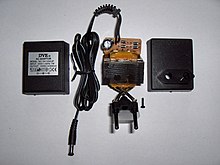
An AC adapter disassembled to reveal a simple, unregulated linear DC supply circuit: a transformer, four diodes in a bridge rectifier, and an electrolytic capacitor to smooth the waveform
In the early twenty-first century, switched-mode power supplies (SMPSs) became almost ubiquitous for this purpose. Mains voltage is rectified to a high direct voltage driving a switching circuit, which contains a transformer operating at a high frequency and outputs direct current at the desired voltage. The high-frequency ripple is more easily filtered out than mains-frequency. The high frequency allows the transformer to be small, which reduces its losses; and the switching regulator can be much more efficient than a linear regulator. The result is a much more efficient, smaller, and lighter device. Safety is ensured, as in the older linear circuit, because there is still a transformer which electrically isolates the output from the mains.
A linear circuit must be designed for a specific, narrow range of input voltages (e.g., 220–240 VAC) and must use a transformer appropriate for the frequency (usually 50 or 60 Hz), but a switched-mode supply can work efficiently over a very wide range of voltages and frequencies; a single 100–240 VAC unit will handle almost any mains supply in the world.
However, unless very carefully designed and using suitable components, switching adapters are more likely to fail than the older type, due in part to complex circuitry and the use of semiconductors. Unless designed well, these adapters may be easily damaged by overloads, even transient ones, which can come from lightning, brief mains overvoltage (sometimes caused by an incandescent light on the same power circuit failing), component degradation, etc. A very common mode of failure is due to the use of electrolytic capacitors whose equivalent series resistance (ESR) increases with age; switching regulators are very sensitive to high ESR (the older linear circuit also used electrolytic capacitors, but the effect of degradation is much less dramatic). Well-designed circuits pay attention to the ESR, ripple current rating, pulse operation, and temperature rating of capacitors.
Advantages
External AC adapters are widely used to power small or portable electronic devices. The advantages include:- Safety – External power adapters can free product designers from worrying about some safety issues. Much of this style of equipment uses only voltages low enough not to be a safety hazard internally, although the power supply must out of necessity use dangerous mains voltage. If an external power supply is used (usually via a power connector, often of coaxial type), the equipment need not be designed with concern for hazardous voltages inside the enclosure. This is particularly relevant for equipment with lightweight cases which may break and expose internal electrical parts.
- Heat reduction – Heat reduces reliability and longevity of electronic components, and can cause sensitive circuits to become inaccurate or malfunction. A separate power supply removes a source of heat from the apparatus.
- Electrical noise reduction – Because radiated electrical noise falls off with the square of the distance, it is to the manufacturer's advantage to convert potentially noisy AC line power or automotive power to "clean", filtered DC in an external adapter, at a safe distance from noise-sensitive circuitry.
- Weight and size reduction – Removing power components and the mains connection plug from equipment powered by rechargeable batteries reduces the weight and size which must be carried.
- Ease of replacement – Power supplies are more prone to failure than other circuitry due to their exposure to power spikes and their internal generation of waste heat. External power supplies can be replaced quickly by a user without the need to have the powered device repaired.
- Configuration versatility – Externally powered electronic products can be used with different power sources as needed (e.g. 120VAC, 240VAC, 12VDC, or external battery pack), for convenient use in the field, or when traveling.
- Simplified product inventory, distribution, and certification – An electronic product that is sold and used internationally must be powered from a wide range of power sources, and must meet product safety regulations in many jurisdictions, usually requiring expensive certification by national or regional safety agencies such as Underwriters Laboratories or Technischer Überwachungsverein. A single version of a device may be used in many markets, with the different power requirements met by different external power supplies, so that only one version of the device need be manufactured, stocked, and tested. If the design of the device is modified over time (a frequent occurrence), the power supply design itself need not be retested (and vice versa).
- Constant voltage is produced by a specific type of adapter used for computers and laptops. These types of adapters are commonly known as eliminators.
Problems

"Power brick" in-line configuration, with detachable AC cord
- Size – Power supplies which plug into the mains directly without using a plug on a cable (true wall warts) are bulkier than bare plugs; sometimes they are too large to plug into power sockets with restricted space, or into adjacent sockets on power strips (due to the fact that they can block other plugs also).
- Weight – Some AC adapters can be heavy, exerting excess weight on the power socket (this depends on the socket design of the country in question). Some external power supplies are "power bricks" (also known as "line lumps") having a short AC cord so they can lie on the floor, thus relieving strain, at the expense of clutter. Other wall-hanging types are made long and thin, minimizing the leverage of their weight vector that pulls the plug out, but exacerbating the size problem. The weight for equipment that must be carried (e.g. for traveling) is not a disadvantage of external supplies, as the alternative is an equally heavy internal supply; but in many cases a single universal supply could replace several proprietary ones.
- Inefficiency – Some idling power is wasted as the power supply is left running when the equipment power switch is off or the equipment is disconnected from the power supply. In recent years, it has become common for equipment with internal supplies to share this problem due to the use of a "soft" power switch.
- Confusion – External power supplies are often generic and not clearly marked to identify the equipment they are designed to power. It is very easy to separate power supply and equipment, and can be difficult to re-match the many devices with their power supplies.
- Compatibility problems – There is no standardization of connectors; the same connector is often used for different voltages, and for both DC supplies and AC-to-AC transformers. Incompatible voltage or polarity may be present on physically interchangeable connectors. This easily leads to using the wrong power supply, which can destroy equipment.
Dangerous and unreliable adapters
Manufacturers of equipment supplied with AC adapters often supply replacements at high prices; this has encouraged the manufacture of compatible third-party aftermarket replacements, which may be of satisfactory quality and performance at significantly lower prices. However, some adapters, usually at very low prices, and sometimes with unknown brands or sometimes fraudulently marked with the name of a reputable manufacturer, have various deficiencies which can cause inadequate performance (e.g. poor regulation and ripple, maximum power capacity lower than specified, hot running), unreliability (e.g. overheating to temperatures exceeding component ratings), and electrical or fire danger to users (e.g. insulation which frays with wear, lack of fuse).Spurious marks of conformity to standards may be present; in one case it was reported that "Chinese manufacturers were submitting well-engineered electrical products to obtain conformity testing reports, but then removing non-essential components in production to reduce costs". A test of 27 chargers found that all the eight legitimately branded with a reputable name met safety standards, but none of those unbranded or with minor names did, despite bearing the
Efficiency (historical)
But others have argued that these inefficient devices are low powered, e.g., devices that are used for small battery chargers, so even if they have a low efficiency, the amount of energy they waste is less than 1% of household consumption of electric energy.
Considering the total efficiency of power supplies for small electronic equipment, the older mains-frequency linear transformer-based power supply was found in a 2002 report to have efficiencies from 20–75%, and have considerable energy loss even when powered up but not supplying power. Switched-mode power supplies (SMPSs) are much more efficient; a good design can be 80–90% efficient, and is also much smaller and lighter. In 2002 most external plug-in "wall wart" power adapters commonly used for low-power consumer electronics devices were of linear design, as well as supplies built into some equipment.
External supplies are usually left plugged in even when not in use, and consume from a few watts to 35 watts of power in that state. The report concluded that about 32 billion kilowatt-hours (kWh) per year, about 1% of total electrical energy consumption, could be saved in the United States by replacing all linear power supplies (average efficiency 40–50%) with advanced switching designs (efficiency 80–90%), by replacing older switching supplies (efficiencies of less than 70%) with advanced designs (efficiency of at least 80%), and by reducing standby consumption of supplies to not more than 1 watt.
Since the report was published, SMPSs have indeed replaced linear supplies to a great extent, even in wall warts. The 2002 report estimated that 6% of electrical energy used in the U.S. "flows through" power supplies (not counting only the wall warts). The website where the report was published said in 2010 that despite the spread of SMPSs, "today's power supplies consume at least 2% of all U.S. electricity production. More efficient power supply designs could cut that usage in half".
Since wasted electrical energy is released as heat, an inefficient power supply is hot to the touch, as is one that wastes power without an electrical load. This waste heat is itself a problem in warm weather, since it may require additional air conditioning to prevent overheating, and even to remove the unwanted heat from large supplies.
Reuse
AC adapters are often reused on other appliances, but there are five parameters which all must suit the appliance:- Voltage
- Current capacity
- Polarity (not relevant with AC)
- Voltage regulation (or stabilization)
- Connector type
Universal power adapters

A six-way connector on a "universal" DC power supply, consisting of a four-way X connector and two separate individual connectors (one is the nine-volt battery connector). The X-connector here provides 3.5 and 2.5 mm phone plugs and two sizes of coaxial power connector
Some "universal" replacement power supplies allow output voltage and polarity to be switched to match a range of equipment. With the advent of switch-mode supplies, adapters which can work with any voltage from 110 VAC to 240 VAC became widely available; previously either 100–120 VAC or 200–240 VAC versions were used. Adaptors which can also be used with motor vehicle and aircraft power (see EmPower) are available.
Four-way X connectors or six-way star connectors, also known as spider connectors, with multiple plug sizes and types are common on generic power supplies. Other replacement power supplies have arrangements for changing the power connector, with four to nine different alternatives available when purchased in a set. RadioShack sells universal AC adapters of various capacities, branded as "Enercell Adaptaplug", and fitted with two-pin female sockets compatible with their Adaptaplug connector lineup. This allows many different configurations of AC adapters to be put together, without requiring soldering. Philmore and other competing brands offer similar AC adapters with interchangeable connectors.
The label on a power supply may not be a reliable guide to the actual voltage it supplies under varying conditions. Many low-cost power supplies are "unregulated", in that their voltage can change considerably with load. If they are lightly loaded, they may put out much more than the nominal "name plate" voltage, which could damage the load. If they are heavily loaded, the output voltage may droop appreciably, in some cases well below the nominal label voltage even within the nominal rated current, causing the equipment being supplied to malfunction or be damaged. Supplies with linear (as against switched) regulators are heavy, bulky, and expensive.
Modern switched-mode power supplies (SMPSs) are smaller, lighter, and more efficient. They put out a much more constant voltage than unregulated supplies as the input voltage and the load current vary. When introduced, their prices were high, but by the early 21st century the prices of switch-mode components had dropped to a degree which allowed even cheap supplies to use this technology, saving the cost of a larger and heavier mains-frequency transformer.
Auto-sensing adapters
Some universal adapters automatically set their output voltage and maximum current according to which of a range of interchangeable tips is fitted; tips are available to fit and supply appropriate power to many notebook computers and mobile devices. Different tips may use the same connector, but automatically supply different power; it is essential to use the right tip for the apparatus being powered, but no switch needs to be set correctly by the user. The advent of switch-mode power supplies has allowed adapters to work from any AC mains supply from 100 to 240V with an appropriate plug; operation from standard 12V DC vehicle and aircraft supplies can also be supported. With the appropriate adapter, accessories, and tips, a variety of equipment can be powered from almost any source of power.A "Green Plug" system has been proposed, based on USB technology, by which the consuming device would tell the external power supply what kind of power is needed.
Use of USB
The USB connector (and voltage) has emerged as a de facto standard in low-power AC adapters for many portable devices. In addition to serial digital data exchange, the USB standard also provides 5 VDC power, up to 500 mA (900 mA over USB 3.0). Numerous accessory gadgets ("USB decorations") were designed to connect to USB only for DC power and not for data interchange. The USB Implementers Forum in March, 2007 released the USB Battery Charging Specification which defines, "...limits as well as detection, control and reporting mechanisms to permit devices to draw current in excess of the USB 2.0 specification for charging ...".Electric fans, lamps, alarms, coffee warmers, battery chargers, and even toys have been designed to tap power from a USB connector. Plug-in adapters equipped with USB receptacles are widely available to convert 120 VAC or 240 VAC power or 12 VDC automotive power to 5 VDC USB power (see photo at right).Standards
The trend towards more-compact electronic devices has driven a shift towards the micro-USB and mini-USB connectors, which are electrically compatible in function to the original USB connector but physically smaller. In 2009, the International Telecommunication Union (ITU) announced support of the Open Mobile Terminal Platform's (OMTP) "Common Charging and Local Data Connectivity" standard. The ITU published Recommendation ITU-T L.1000, "Universal power adapter and charger solution for mobile terminals and other hand-held ICT devices", which specifies a charger similar in most respects to that of the GSMA/OMTP proposal and to the European Common External Power Supply. The ITU recommendation was expanded and updated in June, 2011. The hope is to markedly reduce the profusion of non-interchangeable power adapters.The European Union defined a Common External Power Supply for "hand-held data-enabled mobile phones" (smartphones) sold from 2010, intended to replace the many incompatible proprietary power supplies and eliminate waste by reducing the total number of supplies manufactured. Conformant supplies deliver 5 VDC via a micro-USB connector, with preferred input voltage handled ranging from 90 to 264 VAC.
In 2012, a USB Power Delivery Specification was proposed to standardize delivery of up to 100 watts, suitable for devices such as laptop computers that usually depend on proprietary adapters.
Larry Page, a founder of Google, proposed a 12 V and up to 15 A standard for almost all equipment requiring an external converter, with new buildings fitted with 12 VDC wiring, making external AC-to-DC adapter circuitry unnecessary.
X . IIII
Basic AC-DC Power Supplies
Discrete Semiconductor Devices and Circuits

An adapter is a physical device that allows one hardware or electronic interface to be adapted (accommodated without loss of function) to another hardware or electronic interface. In a computer, an adapter is often built into a card that can be inserted into a slot on the computer's motherboard. The card adapts information that is exchanged between the computer's microprocessor and the devices that the card supports.
Question 1
| Don’t just sit there! Build something!! |
Learning to mathematically analyze circuits requires much study and practice. Typically, students practice by working through lots of sample problems and checking their answers against those provided by the textbook or the instructor. While this is good, there is a much better way.
You will learn much more by actually building and analyzing real circuits, letting your test equipment provide the “answers” instead of a book or another person. For successful circuit-building exercises, follow these steps:
- Carefully measure and record all component values prior to circuit construction, choosing resistor values high enough to make damage to any active components unlikely.
- Draw the schematic diagram for the circuit to be analyzed.
- Carefully build this circuit on a breadboard or other convenient medium.
- Check the accuracy of the circuit’s construction, following each wire to each connection point, and verifying these elements one-by-one on the diagram.
- Mathematically analyze the circuit, solving for all voltage and current values.
- Carefully measure all voltages and currents, to verify the accuracy of your analysis.
- If there are any substantial errors (greater than a few percent), carefully check your circuit’s construction against the diagram, then carefully re-calculate the values and re-measure.
As usual, avoid very high and very low resistor values, to avoid measurement errors caused by meter “loading” (on the high end) and to avoid transistor burnout (on the low end). I recommend resistors between 1 kΩ and 100 kΩ.
One way you can save time and reduce the possibility of error is to begin with a very simple circuit and incrementally add components to increase its complexity after each analysis, rather than building a whole new circuit for each practice problem. Another time-saving technique is to re-use the same components in a variety of different circuit configurations. This way, you won’t have to measure any component’s value more than once.
Question 2
A technician builds a simple half-wave rectifier circuit for a project, but is surprised to find that the diode keeps failing:

This comes as a surprise because the diode has a repetitive peak reverse voltage rating of 50 volts, which the technician knows is greater than the peak voltage output by the step-down transformer. However, the technician has overlooked something very important in this circuit design. Explain what the problem is, and how to solve it.

Question 3
Diodes and capacitors may be interconnected to form a type of circuit that boosts voltage in the process of rectification. This type of circuit is generally known as a voltage multiplier. Shown here are a few different voltage multiplier circuits:

Determine the degree of voltage multiplication (double, triple, etc.) provided by each circuit.

Question 4
Suppose a technician measures the voltage output by an AC-DC power supply circuit:
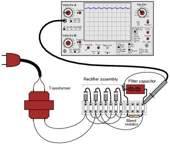
The waveform shown by the oscilloscope is mostly DC, with just a little bit of AC “ripple” voltage appearing as a ripple pattern on what would otherwise be a straight, horizontal line. This is quite normal for the output of an AC-DC power supply.
Suppose we wished to take a closer view of this “ripple” voltage. We want to make the ripples more pronounced on the screen, so that we may better discern their shape. Unfortunately, though, when we decrease the number of volts per division on the “vertical” control knob to magnify the vertical amplification of the oscilloscope, the pattern completely disappears from the screen!
Explain what the problem is, and how we might correct it so as to be able to magnify the ripple voltage waveform without having it disappear off the oscilloscope screen.
Question 5
AC-DC power supply circuits are one of the most common circuit configurations in electronic systems. Though designs may vary, the task of converting AC power to DC power is vital in the functioning of a great many electronic devices.
Why is this? What is it about this kind of circuit that makes it such a necessary part of many electronic systems?
Why is this? What is it about this kind of circuit that makes it such a necessary part of many electronic systems?
Question 6
Although not a popular design, some power supply circuits are transformerless. Direct rectification of AC line power is a viable option in some applications:

However, this form of AC-to-DC power conversion has some significant limits. Explain why most power supply circuits utilize a transformer instead of directly rectifying the line power as this circuit does.

Question 7
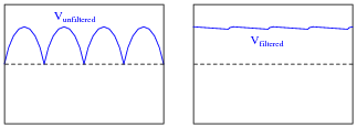
An essential part of an AC-DC power supply circuit is the filter, used to separate the residual AC (called the “ripple” voltage) from the DC voltage prior to output. Here are two simple AC-DC power supply circuits, one without a filter and one with:

Draw the respective output voltage waveforms of these two power supply circuits (Vunfiltered versus Vfiltered). Also identify the type of filter circuit needed for the task (low pass, high pass, band pass, or band stop), and explain why that type of filter circuit is needed.

Question 8
Observe the following two waveforms, as represented on an oscilloscope display measuring output voltage of a filtered power supply:

If both of these waveforms were measured on the same power supply circuit, at different times, determine which waveform was measured during a period of heavier “loading” (a “heavier” load being defined as a load drawing greater current).

Question 11
Suppose a power supply is energized by an AC source of 119 V RMS. The transformer step-down ratio is 8:1, it uses a full-wave bridge rectifier circuit with silicon diodes, and the filter is nothing but a single electrolytic capacitor. Calculate the unloaded DC output voltage for this supply (assume 0.7 volts drop across each diode). Also, write an equation solving for DC output voltage (Vout), given all these parameters.
Question 13
Question 14
Question 15
A student learns that a rectifier circuit is often followed by a low-pass filter circuit in an AC-DC power supply to reduce “ripple” voltage on the output. Looking over his notes from AC theory, the student proceeds to build this power supply circuit complete with a low-pass filter at the output:

While this design will work, there are better filter configurations for this application. Describe the limitations of the circuit shown, and explain how some of the other filters would do a better job.

Question 16
Question 17
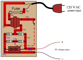
A technician is troubleshooting a power supply circuit with no DC output voltage. The output voltage is supposed to be 15 volts DC:

The technician begins making voltage measurements between some of the test points (TP) on the circuit board. What follows is a sequential record of his measurements:

- VTP9−TP10 = 0 volts DC
- VTP8−TP7 = 0 volts DC
- VTP8−TP5 = 0 volts DC
- VTP6−TP7 = 0 volts DC
- VTP4−TP5 = 0 volts AC
- VTP1−TP3 = 0 volts AC
- VTP1−TP2 = 116 volts AC
Question 18
A technician is troubleshooting a power supply circuit with no DC output voltage. The output voltage is supposed to be 15 volts DC:
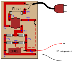
The technician begins making voltage measurements between some of the test points (TP) on the circuit board. What follows is a sequential record of her measurements:

- VTP1−TP2 = 118 volts AC
- VTP3−TP2 = 0 volts AC
- VTP1−TP3 = 118 volts AC
- VTP4−TP5 = 0.5 volts AC
- VTP7−TP8 = 1.1 volts DC
- VTP9−TP10 = 1.1 volts DC
Question 19
A technician is troubleshooting a power supply circuit with no DC output voltage. The output voltage is supposed to be 15 volts DC:

The technician begins making voltage measurements between some of the test points (TP) on the circuit board. What follows is a sequential record of his measurements:

- VTP9−TP10 = 0 volts DC
- VTP1−TP2 = 117 volts AC
- VTP1−TP3 = 117 volts AC
- VTP5−TP6 = 0 volts AC
- VTP7−TP8 = 0.1 volts DC
- VTP5−TP4 = 12 volts AC
- VTP7−TP6 = 0 volts DC
Question 20
AC-DC power supplies are a cause of harmonic currents in AC power systems, especially large AC-DC power supplies used in motor control circuits and other high-power controls. In this example, I show the waveforms for output voltage and input current for an unloaded AC-DC power supply with a step-down transformer, full-wave rectifier, and capacitive filter circuit (the unfiltered DC voltage waveform is shown as a dashed line for reference):

As you can see, the input current waveform lags the voltage waveform by 90o, because when the power supply is unloaded, the only input current is the magnetizing current of the transformer’s primary winding.
With increased loading, the output ripple voltage becomes more pronounced. This also changes the input current waveform significantly, making it non-sinusoidal. Trace the shape of the input current waveform, given the output voltage waveform and magnetizing current waveform (dotted line) shown here:

The non-filtered DC output waveform is still shown as a dotted line, for reference purposes.

With increased loading, the output ripple voltage becomes more pronounced. This also changes the input current waveform significantly, making it non-sinusoidal. Trace the shape of the input current waveform, given the output voltage waveform and magnetizing current waveform (dotted line) shown here:

Question 21
Power supplies are sometimes equipped with EMI/RFI filters on their inputs, to prevent high-frequency “noise” voltage created within the power supply circuit from getting back to the power source where it might interfere with other powered equipment. This is especially useful for “switching” power supply circuits, where transistors are used to switch power on and off very rapidly in the voltage transformation and regulation process:

Determine what type of filter circuit this is (LP, HP, BP, or BS), and also determine the inductive and capacitive reactances of its components at 60 Hz, if the inductors are 100 μH each and the capacitors are 0.022 μF each.

Question 22
Question 23
Predict how all component voltages and currents in this circuit will be affected as a result of the following faults. Consider each fault independently (i.e. one at a time, no multiple faults):


- Any one diode fails open:
- Transformer secondary winding fails open:
- Inductor L1 fails open:
- Capacitor C1 fails shorted:
Question 24
Suppose this power supply circuit was working fine for several years, then one day failed to output any DC voltage at all:

When you open the case of this power supply, you immediately notice the strong odor of burnt components. From this information, determine some likely component faults and explain your reasoning.

Question 25
The ripple frequency of a half-wave rectifier circuit powered by 60 Hz AC is measured to be 60 Hz. The ripple frequency of a full-wave rectifier circuit powered by the exact same 60 Hz AC line voltage is measured to be 120 Hz. Explain why the ripple frequency of the full-wave rectifier is twice that of the half-wave rectifier.
Question 28
A simple AC-DC power supply circuit outputs about 6.1 volts DC without a filter capacitor connected, and about 9.3 volts DC with a filter capacitor connected:

Explain why this is. How can the addition of nothing but a capacitor have such a great effect on the amount of DC voltage output by the circuit?

Explain why this is. How can the addition of nothing but a capacitor have such a great effect on the amount of DC voltage output by the circuit?
Question 29
A technician is troubleshooting a power supply circuit that outputs substantially less DC voltage than it should. The output voltage is supposed to be 15 volts DC, but instead it is actually outputting less than 8 volts DC:

The technician measures approximately 18 volts AC (RMS) across the secondary winding of the transformer. Based on this voltage measurement and the knowledge that there is reduced DC output voltage, identify two possible faults that could account for the problem and all measured values in this circuit, and also identify two circuit elements that could not possibly be to blame (i.e. two things that you know must be functioning properly, no matter what else may be faulted). The circuit elements you identify as either possibly faulted or properly functioning can be wires, traces, and connections as well as components. Be as specific as you can in your answers, identifying both the circuit element and the type of fault.
I’ll let you and your classmates figure out some possibilities here!

- Circuit elements that are possibly faulted
- 1.
- 2.
- Circuit elements that must be functioning properly
- 1.
- 2.
I’ll let you and your classmates figure out some possibilities here!
Notes:
Troubleshooting scenarios are always good for stimulating class discussion. Be sure to spend plenty of time in class with your students developing efficient and logical diagnostic procedures, as this will assist them greatly in their careers.
Troubleshooting scenarios are always good for stimulating class discussion. Be sure to spend plenty of time in class with your students developing efficient and logical diagnostic procedures, as this will assist them greatly in their careers.
Question 30
A technician is troubleshooting a power supply circuit with no DC output voltage. The output voltage is supposed to be 15 volts DC, but instead it is actually outputting nothing at all (zero volts):
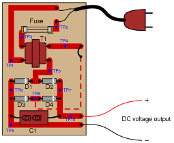
The technician measures 120 volts AC between test points TP1 and TP3. Based on this voltage measurement and the knowledge that there is zero DC output voltage, identify two possible faults that could account for the problem and all measured values in this circuit, and also identify two circuit elements that could not possibly be to blame (i.e. two things that you know must be functioning properly, no matter what else may be faulted). The circuit elements you identify as either possibly faulted or properly functioning can be wires, traces, and connections as well as components. Be as specific as you can in your answers, identifying both the circuit element and the type of fault.

- Circuit elements that are possibly faulted
- 1.
- 2.
- Circuit elements that must be functioning properly
- 1.
- 2.
Question 31
A common sub-circuit in power supplies of all kinds is an EMI/RFI filter. This LC network is all but “transparent” to the 50 or 60 Hz power line frequency, so that the transformer sees full line voltage at all times:

If this EMI/RFI filter does nothing to or with the line power, what purpose does it serve?
An EMI/RFI filter has no purpose in the process of converting AC power into DC power. It does, however, help prevent the power supply circuitry from interfering with other equipment energized by the same AC line power, by filtering out unwanted high-frequency noise generated within the power supply by diode switching.
Follow-up question: calculate the total inductive reactance posed by the two inductors to 60 Hz power if the inductance of each is 100 μH.
Notes:
These filters are very common in switch-mode power supplies, but they are not out of place in linear (“brute-force”) power supply circuits such as this one. Mention to your students how the abatement of electromagnetic and radio frequency interference is a high priority in all kinds of electronic device design.
X . IIIII
Calculus is a branch of mathematics that originated with scientific questions concerning rates of change. The easiest rates of change for most people to understand are those dealing with time. For example, a student watching their savings account dwindle over time as they pay for tuition and other expenses is very concerned with rates of change (dollars per year being spent).
In calculus, we have a special word to describe rates of change: derivative. One of the notations used to express a derivative (rate of change) appears as a fraction. For example, if the variable S represents the amount of money in the student’s savings account and t represents time, the rate of change of dollars over time would be written like this:
The following set of figures puts actual numbers to this hypothetical scenario:
According to the “Ohm’s Law” formula for a capacitor, capacitor current is proportional to the time-derivative of capacitor voltage:
Another way of saying this is to state that the capacitors differentiate voltage with respect to time, and express this time-derivative of voltage as a current.
Suppose we had an oscilloscope capable of directly measuring current, or at least a current-to-voltage converter that we could attach to one of the probe inputs to allow direct measurement of current on one channel. With such an instrument set-up, we could directly plot capacitor voltage and capacitor current together on the same display:
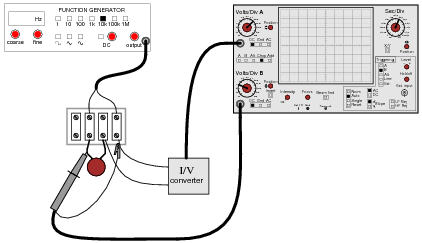
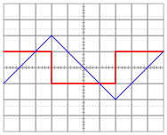
For each of the following voltage waveforms (channel B), plot the corresponding capacitor current waveform (channel A) as it would appear on the oscilloscope screen:
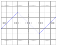


Note: the amplitude of your current plots is arbitrary. What I’m interested in here is the shape of each current waveform!
Potentiometers are very useful devices in the field of robotics, because they allow us to represent the position of a machine part in terms of a voltage. In this particular case, a potentiometer mechanically linked to the joint of a robotic arm represents that arm’s angular position by outputting a corresponding voltage signal:
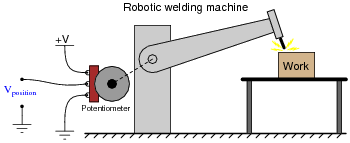
As the robotic arm rotates up and down, the potentiometer wire moves along the resistive strip inside, producing a voltage directly proportional to the arm’s position. A voltmeter connected between the potentiometer wiper and ground will then indicate arm position. A computer with an analog input port connected to the same points will be able to measure, record, and (if also connected to the arm’s motor drive circuits) control the arm’s position.
If we connect the potentiometer’s output to a differentiator circuit, we will obtain another signal representing something else about the robotic arm’s action. What physical variable does the differentiator output signal represent?

One of the fundamental principles of calculus is a process called integration. This principle is important to understand because it is manifested in the behavior of capacitance. Thankfully, there are more familiar physical systems which also manifest the process of integration, making it easier to comprehend.
If we introduce a constant flow of water into a cylindrical tank with water, the water level inside that tank will rise at a constant rate over time:
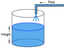
In calculus terms, we would say that the tank integrates water flow into water height. That is, one quantity (flow) dictates the rate-of-change over time of another quantity (height).
Like the water tank, electrical capacitance also exhibits the phenomenon of integration with respect to time. Which electrical quantity (voltage or current) dictates the rate-of-change over time of which other quantity (voltage or current) in a capacitance? Or, to re-phrase the question, which quantity (voltage or current), when maintained at a constant value, results in which other quantity (current or voltage) steadily ramping either up or down over time?
One of the fundamental principles of calculus is a process called integration. This principle is important to understand because it is manifested in the behavior of inductance. Thankfully, there are more familiar physical systems which also manifest the process of integration, making it easier to comprehend.
If we introduce a constant flow of water into a cylindrical tank with water, the water level inside that tank will rise at a constant rate over time:
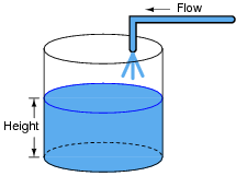
In calculus terms, we would say that the tank integrates water flow into water height. That is, one quantity (flow) dictates the rate-of-change over time of another quantity (height).
Like the water tank, electrical inductance also exhibits the phenomenon of integration with respect to time. Which electrical quantity (voltage or current) dictates the rate-of-change over time of which other quantity (voltage or current) in an inductance? Or, to re-phrase the question, which quantity (voltage or current), when maintained at a constant value, results in which other quantity (current or voltage) steadily ramping either up or down over time?
Both the input and the output of this circuit are square waves, although the output waveform is slightly distorted and also has much less amplitude:

You recognize one of the RC networks as a passive integrator, and the other as a passive differentiator. What does the likeness of the output waveform compared to the input waveform indicate to you about differentiation and integration as functions applied to waveforms?
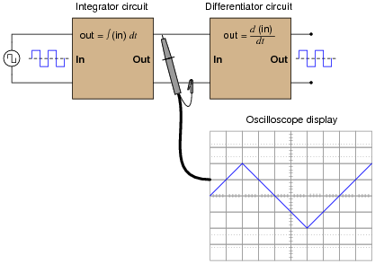
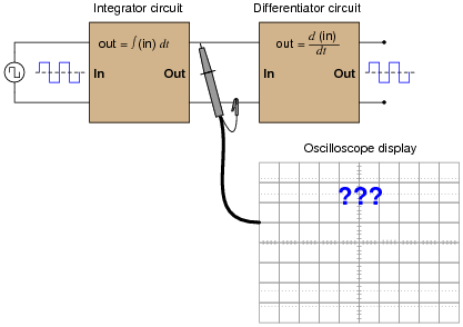
In calculus, differentiation is the inverse operation of something else called integration. That is to say, differentiation “un-does” integration to arrive back at the original function (or signal). To illustrate this electronically, we may connect a differentiator circuit to the output of an integrator circuit and (ideally) get the exact same signal out that we put in:

Based on what you know about differentiation and differentiator circuits, what must the signal look like in between the integrator and differentiator circuits to produce a final square-wave output? In other words, if we were to connect an oscilloscope in between these two circuits, what sort of signal would it show us?
Plot the relationships between voltage and current for resistors of three different values (1 Ω, 2 Ω, and 3 Ω), all on the same graph:

What pattern do you see represented by your three plots? What relationship is there between the amount of resistance and the nature of the voltage/current function as it appears on the graph?
Advanced question: in calculus, the instantaneous rate-of-change of an (x,y) function is expressed through the use of the derivative notation: [dy/dx]. How would the derivative for each of these three plots be properly expressed using calculus notation? Explain how the derivatives of these functions relate to real electrical quantities.
Ohm’s Law tells us that the amount of current through a fixed resistance may be calculated as such:
We could also express this relationship in terms of conductance rather than resistance, knowing that G = 1/R:
However, the relationship between current and voltage for a fixed capacitance is quite different. The “Ohm’s Law” formula for a capacitor is as such:
What significance is there in the use of lower-case variables for current (i) and voltage (e)? Also, what does the expression [de/dt] mean? Note: in case you think that the d’s are variables, and should cancel out in this fraction, think again: this is no ordinary quotient! The d letters represent a calculus concept known as a differential, and a quotient of two d terms is called a derivative.
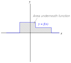
Capacitors store energy in the form of an electric field. We may calculate the energy stored in a capacitance by integrating the product of capacitor voltage and capacitor current (P = IV) over time, since we know that power is the rate at which work (W) is done, and the amount of work done to a capacitor taking it from zero voltage to some non-zero amount of voltage constitutes energy stored (U):
Find a way to substitute capacitance (C) and voltage (V) into the integrand so you may integrate to find an equation describing the amount of energy stored in a capacitor for any given capacitance and voltage values.
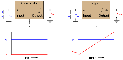
Integrator circuits may be understood in terms of their response to DC input signals: if an integrator receives a steady, unchanging DC input voltage signal, it will output a voltage that changes with a steady rate over time. The rate of the changing output voltage is directly proportional to the magnitude of the input voltage:

A symbolic way of expressing this input/output relationship is by using the concept of the derivative in calculus (a rate of change of one variable compared to another). For an integrator circuit, the rate of output voltage change over time is proportional to the input voltage:
A more sophisticated way of saying this is, “The time-derivative of output voltage is proportional to the input voltage in an integrator circuit.” However, in calculus there is a special symbol used to express this same relationship in reverse terms: expressing the output voltage as a function of the input. For an integrator circuit, this special symbol is called the integration symbol, and it looks like an elongated letter “S”:
Here, we would say that output voltage is proportional to the time-integral of the input voltage, accumulated over a period of time from time=0 to some point in time we call T.
“This is all very interesting,” you say, “but what does this have to do with anything in real life?” Well, there are actually a great deal of applications where physical quantities are related to each other by time-derivatives and time-integrals. Take this water tank, for example:

One of these variables (either height H or flow F, I’m not saying yet!) is the time-integral of the other, just as Vout is the time-integral of Vin in an integrator circuit. What this means is that we could electrically measure one of these two variables in the water tank system (either height or flow) so that it becomes represented as a voltage, then send that voltage signal to an integrator and have the output of the integrator derive the other variable in the system without having to measure it!
Your task is to determine which variable in the water tank scenario would have to be measured so we could electronically predict the other variable using an integrator circuit.
We know that the output of an integrator circuit is proportional to the time-integral of the input voltage:

But how do we turn this proportionality into an exact equality, so that it accounts for the values of R and C? Although the answer to this question is easy enough to simply look up in an electronics reference book, it would be great to actually derive the exact equation from your knowledge of electronic component behaviors! Here are a couple of hints:
If an object moves in a straight line, such as an automobile traveling down a straight road, there are three common measurements we may apply to it: position (x), velocity (v), and acceleration (a). Position, of course, is nothing more than a measure of how far the object has traveled from its starting point. Velocity is a measure of how fast its position is changing over time. Acceleration is a measure of how fast the velocity is changing over time.
These three measurements are excellent illustrations of calculus in action. Whenever we speak of “rates of change,” we are really referring to what mathematicians call derivatives. Thus, when we say that velocity (v) is a measure of how fast the object’s position (x) is changing over time, what we are really saying is that velocity is the “time-derivative” of position. Symbolically, we would express this using the following notation:
Likewise, if acceleration (a) is a measure of how fast the object’s velocity (v) is changing over time, we could use the same notation and say that acceleration is the time-derivative of velocity:
Since it took two differentiations to get from position to acceleration, we could also say that acceleration is the second time-derivative of position:
“What has this got to do with electronics,” you ask? Quite a bit! Suppose we were to measure the velocity of an automobile using a tachogenerator sensor connected to one of the wheels: the faster the wheel turns, the more DC voltage is output by the generator, so that voltage becomes a direct representation of velocity. Now we send this voltage signal to the input of a differentiator circuit, which performs the time-differentiation function on that signal. What would the output of this differentiator circuit then represent with respect to the automobile, position or acceleration? What practical use do you see for such a circuit?
Now suppose we send the same tachogenerator voltage signal (representing the automobile’s velocity) to the input of an integrator circuit, which performs the time-integration function on that signal (which is the mathematical inverse of differentiation, just as multiplication is the mathematical inverse of division). What would the output of this integrator then represent with respect to the automobile, position or acceleration? What practical use do you see for such a circuit?
A familiar context in which to apply and understand basic principles of calculus is the motion of an object, in terms of position (x), velocity (v), and acceleration (a). We know that velocity is the time-derivative of position (v = [dx/dt]) and that acceleration is the time-derivative of velocity (a = [dv/dt]). Another way of saying this is that velocity is the rate of position change over time, and that acceleration is the rate of velocity change over time.
It is easy to construct circuits which input a voltage signal and output either the time-derivative or the time-integral (the opposite of the derivative) of that input signal. We call these circuits “differentiators” and “integrators,” respectively.

Integrator and differentiator circuits are highly useful for motion signal processing, because they allow us to take voltage signals from motion sensors and convert them into signals representing other motion variables. For each of the following cases, determine whether we would need to use an integrator circuit or a differentiator circuit to convert the first type of motion signal into the second:
We know that the output of a differentiator circuit is proportional to the time-derivative of the input voltage:

But how do we turn this proportionality into an exact equality, so that it accounts for the values of R and C? Although the answer to this question is easy enough to simply look up in an electronics reference book, it would be great to actually derive the exact equation from your knowledge of electronic component behaviors! Here are a couple of hints:
You are part of a team building a rocket to carry research instruments into the high atmosphere. One of the variables needed by the on-board flight-control computer is velocity, so it can throttle engine power and achieve maximum fuel efficiency. The problem is, none of the electronic sensors on board the rocket has the ability to directly measure velocity. What is available is an altimeter, which infers the rocket’s altitude (it position away from ground) by measuring ambient air pressure; and also an accelerometer, which infers acceleration (rate-of-change of velocity) by measuring the inertial force exerted by a small mass.
The lack of a “speedometer” for the rocket may have been an engineering design oversight, but it is still your responsibility as a development technician to figure out a workable solution to the dilemma. How do you propose we obtain the electronic velocity measurement the rocket’s flight-control computer needs?
A Rogowski Coil is essentially an air-core current transformer that may be used to measure DC currents as well as AC currents. Like all current transformers, it measures the current going through whatever conductor(s) it encircles.
Normally transformers are considered AC-only devices, because electromagnetic induction requires a changing magnetic field ([(d φ)/dt]) to induce voltage in a conductor. The same is true for a Rogowski coil: it produces a voltage only when there is a change in the measured current. However, we may measure any current (DC or AC) using a Rogowski coil if its output signal feeds into an integrator circuit as shown:

Connected as such, the output of the integrator circuit will be a direct representation of the amount of current going through the wire.
Explain why an integrator circuit is necessary to condition the Rogowski coil’s output so that output voltage truly represents conductor current.
A Rogowski coil has a mutual inductance rating of 5 μH. Calculate the size of the resistor necessary in the integrator circuit to give the integrator output a 1:1 scaling with the measured current, given a capacitor size of 4.7 nF:

That is, size the resistor such that a current through the conductor changing at a rate of 1 amp per second will generate an integrator output voltage changing at a rate of 1 volt per second.
The chain rule of calculus states that:
Similarly, the following mathematical principle is also true:
It is very easy to build an opamp circuit that differentiates a voltage signal with respect to time, such that an input of x produces an output of [dx/dt], but there is no simple circuit that will output the differential of one input signal with respect to a second input signal.
However, this does not mean that the task is impossible. Draw a block diagram for a circuit that calculates [dy/dx], given the input voltages x and y. Hint: this circuit will make use of differentiators.
Challenge question: draw a full opamp circuit to perform this function!
Ohm’s Law tells us that the amount of voltage dropped by a fixed resistance may be calculated as such:
However, the relationship between voltage and current for a fixed inductance is quite different. The “Ohm’s Law” formula for an inductor is as such:
What significance is there in the use of lower-case variables for current (i) and voltage (e)? Also, what does the expression [di/dt] mean? Note: in case you think that the d’s are variables, and should cancel out in this fraction, think again: this is no ordinary quotient! The d letters represent a calculus concept known as a differential, and a quotient of two d terms is called a derivative.
Digital logic circuits, which comprise the inner workings of computers, are essentially nothing more than arrays of switches made from semiconductor components called transistors. As switches, these circuits have but two states: on and off, which represent the binary states of 1 and 0, respectively.
The faster these switch circuits are able to change state, the faster the computer can perform arithmetic and do all the other tasks computers do. To this end, computer engineers keep pushing the limits of transistor circuit design to achieve faster and faster switching rates.
This race for speed causes problems for the power supply circuitry of computers, though, because of the current “surges” (technically called transients) created in the conductors carrying power from the supply to the logic circuits. The faster these logic circuits change state, the greater the [di/dt] rates-of-change exist in the conductors carrying current to power them. Significant voltage drops can occur along the length of these conductors due to their parasitic inductance:

Suppose a logic gate circuit creates transient currents of 175 amps per nanosecond (175 A/ns) when switching from the “off” state to the “on” state. If the total inductance of the power supply conductors is 10 picohenrys (9.5 pH), and the power supply voltage is 5 volts DC, how much voltage remains at the power terminals of the logic gate during one of these “surges”?
Inductors store energy in the form of a magnetic field. We may calculate the energy stored in an inductance by integrating the product of inductor voltage and inductor current (P = IV) over time, since we know that power is the rate at which work (W) is done, and the amount of work done to an inductor taking it from zero current to some non-zero amount of current constitutes energy stored (U):
Find a way to substitute inductance (L) and current (I) into the integrand so you may integrate to find an equation describing the amount of energy stored in an inductor for any given inductance and current values.
Calculus is widely (and falsely!) believed to be too complicated for the average person to understand. Yet, anyone who has ever driven a car has an intuitive grasp of calculus’ most basic concepts: differentiation and integration. These two complementary operations may be seen at work on the instrument panel of every automobile:

On this one instrument, two measurements are given: speed in miles per hour, and distance traveled in miles. In areas where metric units are used, the units would be kilometers per hour and kilometers, respectively. Regardless of units, the two variables of speed and distance are related to each other over time by the calculus operations of integration and differentiation. My question for you is which operation goes which way?
We know that speed is the rate of change of distance over time. This much is apparent simply by examining the units (miles per hour indicates a rate of change over time). Of these two variables, speed and distance, which is the derivative of the other, and which is the integral of the other? Also, determine what happens to the value of each one as the other maintains a constant (non-zero) value.
A forward-biased PN semiconductor junction does not possess a “resistance” in the same manner as a resistor or a length of wire. Any attempt at applying Ohm’s Law to a diode, then, is doomed from the start.
This is not to say that we cannot assign a dynamic value of resistance to a PN junction, though. The fundamental definition of resistance comes from Ohm’s Law, and it is expressed in derivative form as such:
The fundamental equation relating current and voltage together for a PN junction is Shockley’s diode equation:
At room temperature (approximately 21 degrees C, or 294 degrees K), the thermal voltage of a PN junction is about 25 millivolts. Substituting 1 for the non-ideality coefficient, we may simply the diode equation as such:
Differentiate this equation with respect to V, so as to determine [dI/dV], and then reciprocate to find a mathematical definition for dynamic resistance ([dV/dI]) of a PN junction. Hints: saturation current (IS) is a very small constant for most diodes, and the final equation should express dynamic resistance in terms of thermal voltage (25 mV) and diode current (I).
Just as addition is the inverse operation of subtraction, and multiplication is the inverse operation of division, a calculus concept known as integration is the inverse function of differentiation. Symbolically, integration is represented by a long “S”-shaped symbol called the integrand:
To be truthful, there is a bit more to this reciprocal relationship than what is shown above, but the basic idea you need to grasp is that integration “un-does” differentiation, and visa-versa. Derivatives are a bit easier for most people to understand, so these are generally presented before integrals in calculus courses. One common application of derivatives is in the relationship between position, velocity, and acceleration of a moving object. Velocity is nothing more than rate-of-change of position over time, and acceleration is nothing more than rate-of-change of velocity over time:
Illustrating this in such a way that shows differentiation as a process:

Given that you know integration is the inverse-function of differentiation, show how position, velocity, and acceleration are related by integration. Show this both in symbolic (proper mathematical) form as well as in an illustration similar to that shown above.
It is perfectly accurate to say that differentiation undoes integration, so that [d/dt] ∫x dt = x, but to say that integration undoes differentiation is not entirely true because indefinite integration always leaves a constant C that may very well be non-zero, so that ∫[dx/dt] dt = x + C rather than simply being x.
Calculus is a branch of mathematics that originated with scientific questions concerning rates of change. The easiest rates of change for most people to understand are those dealing with time. For example, a student watching their savings account dwindle over time as they pay for tuition and other expenses is very concerned with rates of change (dollars per day being spent).
The “derivative” is how rates of change are symbolically expressed in mathematical equations. For example, if the variable S represents the amount of money in the student’s savings account and t represents time, the rate of change of dollars over time (the time-derivative of the student’s account balance) would be written as [dS/dt]. The process of calculating this rate of change from a record of the account balance over time, or from an equation describing the balance over time, is called differentiation.
Suppose, though, that instead of the bank providing the student with a statement every month showing the account balance on different dates, the bank were to provide the student with a statement every month showing the rates of change of the balance over time, in dollars per day, calculated at the end of each day:

Explain how the Isaac Newton Credit Union calculates the derivative ([dS/dt]) from the regular account balance numbers (S in the Humongous Savings & Loan statement), and then explain how the student who banks at Isaac Newton Credit Union could figure out how much money is in their account at any given time.
Hint: the process of calculating a variable’s value from rates of change is called integration in calculus. It is the opposite (inverse) function of differentiation.
The Isaac Newton Credit Union differentiates S by dividing the difference between consecutive balances by the number of days between those balance figures. Differentiation is fundamentally a process of division.
To integrate the [dS/dt] values shown on the Credit Union’s statement so as to arrive at values for S, we must either repeatedly add or subtract the days’ rate-of-change figures, beginning with a starting balance. Thus, integration is fundamentally a process of multiplication.
Follow-up question: explain why a starting balance is absolutely necessary for the student banking at Isaac Newton Credit Union to know in order for them to determine their account balance at any time. Why would it be impossible for them to figure out how much money was in their account if the only information they possessed was the [dS/dt] figures?
These filters are very common in switch-mode power supplies, but they are not out of place in linear (“brute-force”) power supply circuits such as this one. Mention to your students how the abatement of electromagnetic and radio frequency interference is a high priority in all kinds of electronic device design.
X . IIIII
Calculus for Electric Circuits
Mathematics for Electronics
Question 1
|
Calculus is a branch of mathematics that originated with scientific questions concerning rates of change. The easiest rates of change for most people to understand are those dealing with time. For example, a student watching their savings account dwindle over time as they pay for tuition and other expenses is very concerned with rates of change (dollars per year being spent).
In calculus, we have a special word to describe rates of change: derivative. One of the notations used to express a derivative (rate of change) appears as a fraction. For example, if the variable S represents the amount of money in the student’s savings account and t represents time, the rate of change of dollars over time would be written like this:
|
- Date: November 20
- Saving account balance (S) = $12,527.33
- Rate of spending ([dS/dt]) = -5,749.01 per year
Question 2
∫f(x) dx Calculus alert! |
|
Suppose we had an oscilloscope capable of directly measuring current, or at least a current-to-voltage converter that we could attach to one of the probe inputs to allow direct measurement of current on one channel. With such an instrument set-up, we could directly plot capacitor voltage and capacitor current together on the same display:


Question 3
∫f(x) dx Calculus alert! |

If we connect the potentiometer’s output to a differentiator circuit, we will obtain another signal representing something else about the robotic arm’s action. What physical variable does the differentiator output signal represent?

Question 4
|
One of the fundamental principles of calculus is a process called integration. This principle is important to understand because it is manifested in the behavior of capacitance. Thankfully, there are more familiar physical systems which also manifest the process of integration, making it easier to comprehend.
If we introduce a constant flow of water into a cylindrical tank with water, the water level inside that tank will rise at a constant rate over time:

Like the water tank, electrical capacitance also exhibits the phenomenon of integration with respect to time. Which electrical quantity (voltage or current) dictates the rate-of-change over time of which other quantity (voltage or current) in a capacitance? Or, to re-phrase the question, which quantity (voltage or current), when maintained at a constant value, results in which other quantity (current or voltage) steadily ramping either up or down over time?
Question 5
|
One of the fundamental principles of calculus is a process called integration. This principle is important to understand because it is manifested in the behavior of inductance. Thankfully, there are more familiar physical systems which also manifest the process of integration, making it easier to comprehend.
If we introduce a constant flow of water into a cylindrical tank with water, the water level inside that tank will rise at a constant rate over time:

Like the water tank, electrical inductance also exhibits the phenomenon of integration with respect to time. Which electrical quantity (voltage or current) dictates the rate-of-change over time of which other quantity (voltage or current) in an inductance? Or, to re-phrase the question, which quantity (voltage or current), when maintained at a constant value, results in which other quantity (current or voltage) steadily ramping either up or down over time?
Question 6
∫f(x) dx Calculus alert! |

Question 7
Question 8
∫f(x) dx Calculus alert! |


Question 9
|
Plot the relationships between voltage and current for resistors of three different values (1 Ω, 2 Ω, and 3 Ω), all on the same graph:

Advanced question: in calculus, the instantaneous rate-of-change of an (x,y) function is expressed through the use of the derivative notation: [dy/dx]. How would the derivative for each of these three plots be properly expressed using calculus notation? Explain how the derivatives of these functions relate to real electrical quantities.
Question 10
|
Ohm’s Law tells us that the amount of current through a fixed resistance may be calculated as such:
|
|
|
Question 11
|
Capacitors store energy in the form of an electric field. We may calculate the energy stored in a capacitance by integrating the product of capacitor voltage and capacitor current (P = IV) over time, since we know that power is the rate at which work (W) is done, and the amount of work done to a capacitor taking it from zero voltage to some non-zero amount of voltage constitutes energy stored (U):
|
|
|
Question 12
|
Integrator circuits may be understood in terms of their response to DC input signals: if an integrator receives a steady, unchanging DC input voltage signal, it will output a voltage that changes with a steady rate over time. The rate of the changing output voltage is directly proportional to the magnitude of the input voltage:

|
|
“This is all very interesting,” you say, “but what does this have to do with anything in real life?” Well, there are actually a great deal of applications where physical quantities are related to each other by time-derivatives and time-integrals. Take this water tank, for example:

Your task is to determine which variable in the water tank scenario would have to be measured so we could electronically predict the other variable using an integrator circuit.
Question 13
|
We know that the output of an integrator circuit is proportional to the time-integral of the input voltage:

|
|
Question 14
|
If an object moves in a straight line, such as an automobile traveling down a straight road, there are three common measurements we may apply to it: position (x), velocity (v), and acceleration (a). Position, of course, is nothing more than a measure of how far the object has traveled from its starting point. Velocity is a measure of how fast its position is changing over time. Acceleration is a measure of how fast the velocity is changing over time.
These three measurements are excellent illustrations of calculus in action. Whenever we speak of “rates of change,” we are really referring to what mathematicians call derivatives. Thus, when we say that velocity (v) is a measure of how fast the object’s position (x) is changing over time, what we are really saying is that velocity is the “time-derivative” of position. Symbolically, we would express this using the following notation:
|
|
|
Now suppose we send the same tachogenerator voltage signal (representing the automobile’s velocity) to the input of an integrator circuit, which performs the time-integration function on that signal (which is the mathematical inverse of differentiation, just as multiplication is the mathematical inverse of division). What would the output of this integrator then represent with respect to the automobile, position or acceleration? What practical use do you see for such a circuit?
Question 15
|
A familiar context in which to apply and understand basic principles of calculus is the motion of an object, in terms of position (x), velocity (v), and acceleration (a). We know that velocity is the time-derivative of position (v = [dx/dt]) and that acceleration is the time-derivative of velocity (a = [dv/dt]). Another way of saying this is that velocity is the rate of position change over time, and that acceleration is the rate of velocity change over time.
It is easy to construct circuits which input a voltage signal and output either the time-derivative or the time-integral (the opposite of the derivative) of that input signal. We call these circuits “differentiators” and “integrators,” respectively.

- Converting velocity signal to position signal: (integrator or differentiator?)
- Converting acceleration signal to velocity signal: (integrator or differentiator?)
- Converting position signal to velocity signal: (integrator or differentiator?)
- Converting velocity signal to acceleration signal: (integrator or differentiator?)
- Converting acceleration signal to position signal: (integrator or differentiator?)
Question 16
|
We know that the output of a differentiator circuit is proportional to the time-derivative of the input voltage:

|
|
Question 17
|
You are part of a team building a rocket to carry research instruments into the high atmosphere. One of the variables needed by the on-board flight-control computer is velocity, so it can throttle engine power and achieve maximum fuel efficiency. The problem is, none of the electronic sensors on board the rocket has the ability to directly measure velocity. What is available is an altimeter, which infers the rocket’s altitude (it position away from ground) by measuring ambient air pressure; and also an accelerometer, which infers acceleration (rate-of-change of velocity) by measuring the inertial force exerted by a small mass.
The lack of a “speedometer” for the rocket may have been an engineering design oversight, but it is still your responsibility as a development technician to figure out a workable solution to the dilemma. How do you propose we obtain the electronic velocity measurement the rocket’s flight-control computer needs?
Question 18
|
A Rogowski Coil is essentially an air-core current transformer that may be used to measure DC currents as well as AC currents. Like all current transformers, it measures the current going through whatever conductor(s) it encircles.
Normally transformers are considered AC-only devices, because electromagnetic induction requires a changing magnetic field ([(d φ)/dt]) to induce voltage in a conductor. The same is true for a Rogowski coil: it produces a voltage only when there is a change in the measured current. However, we may measure any current (DC or AC) using a Rogowski coil if its output signal feeds into an integrator circuit as shown:

Explain why an integrator circuit is necessary to condition the Rogowski coil’s output so that output voltage truly represents conductor current.
Question 19
|
A Rogowski coil has a mutual inductance rating of 5 μH. Calculate the size of the resistor necessary in the integrator circuit to give the integrator output a 1:1 scaling with the measured current, given a capacitor size of 4.7 nF:

Question 20
|
The chain rule of calculus states that:
|
|
However, this does not mean that the task is impossible. Draw a block diagram for a circuit that calculates [dy/dx], given the input voltages x and y. Hint: this circuit will make use of differentiators.
Challenge question: draw a full opamp circuit to perform this function!
Question 21
|
Ohm’s Law tells us that the amount of voltage dropped by a fixed resistance may be calculated as such:
|
|
Question 22
|
Digital logic circuits, which comprise the inner workings of computers, are essentially nothing more than arrays of switches made from semiconductor components called transistors. As switches, these circuits have but two states: on and off, which represent the binary states of 1 and 0, respectively.
The faster these switch circuits are able to change state, the faster the computer can perform arithmetic and do all the other tasks computers do. To this end, computer engineers keep pushing the limits of transistor circuit design to achieve faster and faster switching rates.
This race for speed causes problems for the power supply circuitry of computers, though, because of the current “surges” (technically called transients) created in the conductors carrying power from the supply to the logic circuits. The faster these logic circuits change state, the greater the [di/dt] rates-of-change exist in the conductors carrying current to power them. Significant voltage drops can occur along the length of these conductors due to their parasitic inductance:

Question 23
|
Inductors store energy in the form of a magnetic field. We may calculate the energy stored in an inductance by integrating the product of inductor voltage and inductor current (P = IV) over time, since we know that power is the rate at which work (W) is done, and the amount of work done to an inductor taking it from zero current to some non-zero amount of current constitutes energy stored (U):
|
|
|
Question 24
Question 25
Question 26
∫f(x) dx Calculus alert! |

We know that speed is the rate of change of distance over time. This much is apparent simply by examining the units (miles per hour indicates a rate of change over time). Of these two variables, speed and distance, which is the derivative of the other, and which is the integral of the other? Also, determine what happens to the value of each one as the other maintains a constant (non-zero) value.
Question 27
Question 28
∫f(x) dx Calculus alert! |
This is not to say that we cannot assign a dynamic value of resistance to a PN junction, though. The fundamental definition of resistance comes from Ohm’s Law, and it is expressed in derivative form as such:
|
|
|
Question 29
|
Just as addition is the inverse operation of subtraction, and multiplication is the inverse operation of division, a calculus concept known as integration is the inverse function of differentiation. Symbolically, integration is represented by a long “S”-shaped symbol called the integrand:
|
|
|
|

Footnotes:
It is perfectly accurate to say that differentiation undoes integration, so that [d/dt] ∫x dt = x, but to say that integration undoes differentiation is not entirely true because indefinite integration always leaves a constant C that may very well be non-zero, so that ∫[dx/dt] dt = x + C rather than simply being x.
Question 30
|
Calculus is a branch of mathematics that originated with scientific questions concerning rates of change. The easiest rates of change for most people to understand are those dealing with time. For example, a student watching their savings account dwindle over time as they pay for tuition and other expenses is very concerned with rates of change (dollars per day being spent).
The “derivative” is how rates of change are symbolically expressed in mathematical equations. For example, if the variable S represents the amount of money in the student’s savings account and t represents time, the rate of change of dollars over time (the time-derivative of the student’s account balance) would be written as [dS/dt]. The process of calculating this rate of change from a record of the account balance over time, or from an equation describing the balance over time, is called differentiation.
Suppose, though, that instead of the bank providing the student with a statement every month showing the account balance on different dates, the bank were to provide the student with a statement every month showing the rates of change of the balance over time, in dollars per day, calculated at the end of each day:

Hint: the process of calculating a variable’s value from rates of change is called integration in calculus. It is the opposite (inverse) function of differentiation.
The Isaac Newton Credit Union differentiates S by dividing the difference between consecutive balances by the number of days between those balance figures. Differentiation is fundamentally a process of division.
To integrate the [dS/dt] values shown on the Credit Union’s statement so as to arrive at values for S, we must either repeatedly add or subtract the days’ rate-of-change figures, beginning with a starting balance. Thus, integration is fundamentally a process of multiplication.
Follow-up question: explain why a starting balance is absolutely necessary for the student banking at Isaac Newton Credit Union to know in order for them to determine their account balance at any time. Why would it be impossible for them to figure out how much money was in their account if the only information they possessed was the [dS/dt] figures?
Notes:
The purpose of this question is to introduce the concept of the integral to students in a way that is familiar to them. Hopefully the opening scenario of a dwindling savings account is something they can relate to!
Some students may ask why the differential notation [dS/dt] is used rather than the difference notation [(∆S)/(∆t)] in this example, since the rates of change are always calculated by subtraction of two data points (thus implying a ∆). Given that the function here is piecewise and not continuous, one could argue that it is not differentiable at the points of interest. My purpose in using differential notation is to familiarize students with the concept of the derivative in the context of something they can easily relate to, even if the particular details of the application suggest a more correct notation.
X . IIIIII
Learning to mathematically analyze circuits requires much study and practice. Typically, students practice by working through lots of sample problems and checking their answers against those provided by the textbook or the instructor. While this is good, there is a much better way.
You will learn much more by actually building and analyzing real circuits, letting your test equipment provide the “answers” instead of a book or another person. For successful circuit-building exercises, follow these steps:
As usual, avoid very high and very low resistor values, to avoid measurement errors caused by meter “loading” (on the high end) and to avoid transistor burnout (on the low end). I recommend resistors between 1 kΩ and 100 kΩ.
One way you can save time and reduce the possibility of error is to begin with a very simple circuit and incrementally add components to increase its complexity after each analysis, rather than building a whole new circuit for each practice problem. Another time-saving technique is to re-use the same components in a variety of different circuit configurations. This way, you won’t have to measure any component’s value more than once.
The purpose of this question is to introduce the concept of the integral to students in a way that is familiar to them. Hopefully the opening scenario of a dwindling savings account is something they can relate to!
Some students may ask why the differential notation [dS/dt] is used rather than the difference notation [(∆S)/(∆t)] in this example, since the rates of change are always calculated by subtraction of two data points (thus implying a ∆). Given that the function here is piecewise and not continuous, one could argue that it is not differentiable at the points of interest. My purpose in using differential notation is to familiarize students with the concept of the derivative in the context of something they can easily relate to, even if the particular details of the application suggest a more correct notation.
X . IIIIII
JFET Amplifiers
Discrete Semiconductor Devices and Circuits
Question 1
| Don’t just sit there! Build something!! |
Learning to mathematically analyze circuits requires much study and practice. Typically, students practice by working through lots of sample problems and checking their answers against those provided by the textbook or the instructor. While this is good, there is a much better way.
You will learn much more by actually building and analyzing real circuits, letting your test equipment provide the “answers” instead of a book or another person. For successful circuit-building exercises, follow these steps:
- Carefully measure and record all component values prior to circuit construction, choosing resistor values high enough to make damage to any active components unlikely.
- Draw the schematic diagram for the circuit to be analyzed.
- Carefully build this circuit on a breadboard or other convenient medium.
- Check the accuracy of the circuit’s construction, following each wire to each connection point, and verifying these elements one-by-one on the diagram.
- Mathematically analyze the circuit, solving for all voltage and current values.
- Carefully measure all voltages and currents, to verify the accuracy of your analysis.
- If there are any substantial errors (greater than a few percent), carefully check your circuit’s construction against the diagram, then carefully re-calculate the values and re-measure.
As usual, avoid very high and very low resistor values, to avoid measurement errors caused by meter “loading” (on the high end) and to avoid transistor burnout (on the low end). I recommend resistors between 1 kΩ and 100 kΩ.
One way you can save time and reduce the possibility of error is to begin with a very simple circuit and incrementally add components to increase its complexity after each analysis, rather than building a whole new circuit for each practice problem. Another time-saving technique is to re-use the same components in a variety of different circuit configurations. This way, you won’t have to measure any component’s value more than once.
Question 2
This relaxation oscillator circuit uses a resistor-capacitor combination (R1 - C1) to establish the time delay between output pulses:

The voltage measured between TP1 and ground looks like this on the oscilloscope display:

A slightly different version of this circuit adds a JFET to the capacitor’s charge current path:

Now, the voltage at TP1 looks like this:
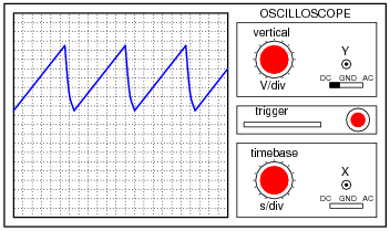
What function does the JFET perform in this circuit, based on your analysis of the new TP1 signal waveform? The straight-line charging voltage pattern shown on the second oscilloscope display indicates what the JFET is doing in this circuit.
Hint: you don’t need to know anything about the function of the unijunction transistor (at the circuit’s output) other than it acts as an on/off switch to periodically discharge the capacitor when the TP1 voltage reaches a certain threshold level.
Challenge question: write a formula predicting the slope of the ramping voltage waveform measured at TP1.
Question 3
A student builds this transistor amplifier circuit on a solderless “breadboard”:

The purpose of the potentiometer is to provide an adjustable DC bias voltage for the transistor, so it may be operated in Class-A mode. After some adjustment of this potentiometer, the student is able to obtain good amplification from the transistor (signal generators and oscilloscopes have been omitted from the illustration for simplicity).
Later, the student accidently adjusts the power supply voltage to a level beyond the JFET’s rating, destroying the transistor. Re-setting the power supply voltage back where the student began the experiment and replacing the transistor, the student discovers that the biasing potentiometer must be re-adjusted to achieve good Class-A operation.
Intrigued by this discovery, the student decides to replace this transistor with a third (of the same part number, of course), just to see if the biasing potentiometer needs to be adjusted again for good Class-A operation. It does.
Explain why this is so. Why must the gate biasing potentiometer be re-adjusted every time the transistor is replaced, even if the replacement transistor(s) are of the exact same type?
Question 4
Question 5
The voltage gain for a “bypassed” common-emitter BJT amplifier circuit is as follows:

Common-source JFET amplifier circuits are very similar:

One of the problems with “bypassed” amplifier configurations such as the common-emitter and common-source is voltage gain variability. It is difficult to keep the voltage gain stable in either type of amplifier, due to changing factors within the transistors themselves which cannot be tightly controlled (r′e and gm, respectively). One solution to this dilemma is to “swamp” those uncontrollable factors by not bypassing the emitter (or source) resistor. The result is greater AV stability at the expense of AV magnitude:

Write the voltage gain equations for both “swamped” BJT and JFET amplifier configurations, and explain why they are similar to each other.


Question 6
The circuit shown here is a precision DC voltmeter:

Explain why this circuit design requires the use of a field-effect transistor, and not a bipolar junction transistor (BJT).
Also, answer the following questions about the circuit:

Also, answer the following questions about the circuit:
- Explain, step by step, how an increasing input voltage between the test probes causes the meter movement to deflect further.
- If the most sensitive range of this voltmeter is 0.1 volts (full-scale), calculate the other range values, and label them on the schematic next to their respective switch positions.
- What type of JFET configuration is this (common-gate, common-source, or common-drain)?
- What purpose does the capacitor serve in this circuit?
- What detrimental effect would result from installing a capacitor that was too large?
- Estimate a reasonable value for the capacitor’s capacitance.
- Explain the functions of the “Zero” and “Span” calibration potentiometers.
Question 7
This is a schematic of an RF amplifier using a JFET as the active element:

What configuration of JFET amplifier is this (common drain, common gate, or common source)? Also, explain the purpose of the two iron-core inductors in this circuit. Hint: inductors L1 and L2 are often referred to as RF chokes.

Question 8
Calculate the approximate input impedance of this JFET amplifier circuit:

Explain why it is easier to calculate the Zin of a JFET circuit like this than it is to calculate the Zin of a similar bipolar transistor amplifier circuit. Also, explain how calculation of this amplifier’s output impedance compares with that of a similar BJT amplifier circuit - same approach or different approach?

Question 9
Define what a common-source transistor amplifier circuit is. What distinguishes this amplifier configuration from the other single-FET amplifier configurations, namely common-drain and common-gate? What configuration of BJT amplifier circuit does the common-source FET circuit most resemble in form and behavior?
Also, describe the typical voltage gains of this amplifier configuration, and whether it is inverting or non-inverting.
Also, describe the typical voltage gains of this amplifier configuration, and whether it is inverting or non-inverting.
Question 10
Define what a common-gate transistor amplifier circuit is. What distinguishes this amplifier configuration from the other single-FET amplifier configurations, namely common-drain and common-source? What configuration of BJT amplifier circuit does the common-gate FET circuit most resemble in form and behavior?
Also, describe the typical voltage gains of this amplifier configuration, and whether it is inverting or non-inverting.
Also, describe the typical voltage gains of this amplifier configuration, and whether it is inverting or non-inverting.
Question 11
Define what a common-drain transistor amplifier circuit is. What distinguishes this amplifier configuration from the other single-FET amplifier configurations, namely common-source and common-gate? What configuration of BJT amplifier circuit does the common-drain FET circuit most resemble in form and behavior?
Also, describe the typical voltage gains of this amplifier configuration, and whether it is inverting or non-inverting.
Also, describe the typical voltage gains of this amplifier configuration, and whether it is inverting or non-inverting.
Question 12
Determine whether this amplifier circuit is inverting or non-inverting (i.e. the phase shift between input and output waveforms):

Be sure to explain, step by step, how you were able to determine the phase relationship between input and output in this circuit. Also identify the type of amplifier each transistor represents (common-???).

Question 13
It is a well-known fact that temperature affects the operating parameters of bipolar junction transistors. This is why grounded-emitter circuits (with no emitter feedback resistor) are not practical as stand-alone amplifier circuits.
Does temperature affect junction field-effect transistors in the same way, or to the same extent? Design an experiment to determine the answer to this question.
Does temperature affect junction field-effect transistors in the same way, or to the same extent? Design an experiment to determine the answer to this question.
Question 14
Question 15
The following circuit is a “multi-coupler” for audio signals: one audio signal source (such as a microphone) is distributed to three different outputs:

Suppose an audio signal is getting through from the input to outputs 2 and 3, but not through to output 1. Identify possible failures in the circuit that could cause this. Be as specific as you can, and identify how you would confirm each type of failure using a multimeter.
X . IIIIIII
Learning to analyze digital circuits requires much study and practice. Typically, students practice by working through lots of sample problems and checking their answers against those provided by the textbook or the instructor. While this is good, there is a much better way.
You will learn much more by actually building and analyzing real circuits, letting your test equipment provide the “answers” instead of a book or another person. For successful circuit-building exercises, follow these steps:
One way you can save time and reduce the possibility of error is to begin with a very simple circuit and incrementally add components to increase its complexity after each analysis, rather than building a whole new circuit for each practice problem. Another time-saving technique is to re-use the same components in a variety of different circuit configurations. This way, you won’t have to measure any component’s value more than once.

X . IIIIIII
Digital Communication
Digital Circuits
Question 1
| Don’t just sit there! Build something!! |
You will learn much more by actually building and analyzing real circuits, letting your test equipment provide the “answers” instead of a book or another person. For successful circuit-building exercises, follow these steps:
- Draw the schematic diagram for the digital circuit to be analyzed.
- Carefully build this circuit on a breadboard or other convenient medium.
- Check the accuracy of the circuit’s construction, following each wire to each connection point, and verifying these elements one-by-one on the diagram.
- Analyze the circuit, determining all output logic states for given input conditions.
- Carefully measure those logic states, to verify the accuracy of your analysis.
- If there are any errors, carefully check your circuit’s construction against the diagram, then carefully re-analyze the circuit and re-measure.
One way you can save time and reduce the possibility of error is to begin with a very simple circuit and incrementally add components to increase its complexity after each analysis, rather than building a whole new circuit for each practice problem. Another time-saving technique is to re-use the same components in a variety of different circuit configurations. This way, you won’t have to measure any component’s value more than once.
Question 3
The following schematic diagram shows two four-bit universal shift registers used to communicate data serially over a coaxial cable of unspecified length:

Specify what logic states would have to be input at the PL, CE, and Clk terminals of each shift register, and at what times, to successfully load four bits of parallel data, shift them serially over the coaxial data cable, and then hold them at the outputs (Q) of the receiving shift register.

Question 4
Personal computers and peripheral devices provide a rich source of examples for both serial and parallel data transmission. Identify some common examples of both serial and parallel data transmission networks (and standards) at work in a common personal computer. Examples may include communication between computers, between computers and peripheral devices (printers, scanners, cameras, special cards), or between fundamental components of the computer (CPU, disk drive, monitor, etc.).
Question 5
A ubiquitous example of serial data communication is the cable linking a keyboard to a personal computer: for every key switch pressed, an ASCII character is transmitted to the computer. An interesting characteristic of this particular communication protocol is the random rate at which the ASCII characters are sent. Because the characters are generated at the rate the computer user happens to type, the rate is completely unpredictable. Consequently, this form of serial data communication is known as asynchronous.
Compare and contrast this against synchronous serial data communication, giving an example of a synchronous data communications standard.
Compare and contrast this against synchronous serial data communication, giving an example of a synchronous data communications standard.
Question 6
Question 7
Question 8
Question 9
Question 10
In Claude Shannon’s famous 1948 paper entitled A Mathematical Theory of Communication, he opens with the following statement:
Digital signals are highly resistant to corruption from noise, because they are composed of discrete (“high” and “low”) states rather than continuously-variable quantities as analog signals are. However, in order to communicate any significant measure of digital information in serial form, many pulses are needed. This requires a high-bandwidth data path to be comparable in speed to analog.
X . IIIIIII
The resistors prevent the (unlikely) occurrence of a short-circuit between two or more inverter gates, if one gate happens to fail high or low, or if some gates are significantly slower than others (and thus will “fight” with the faster gates during each transition).
Challenge question: adding inverter gates to the output of this circuit has an interesting effect on the duty cycle control. The potentiometer will now act backward from the way it was before (decreasing duty cycle when it formerly increased duty cycle, and visa-versa). Explain why.
- “The recent development of various methods of modulation such as PCM and PPM which exchange bandwidth for signal-to-noise ratio has intensified the interest in a general theory of communication.”
Digital signals are highly resistant to corruption from noise, because they are composed of discrete (“high” and “low”) states rather than continuously-variable quantities as analog signals are. However, in order to communicate any significant measure of digital information in serial form, many pulses are needed. This requires a high-bandwidth data path to be comparable in speed to analog.
Notes:
Shannon’s language is perhaps a bit above the norm for technician-level education, but it nevertheless captures an important quality of digital communication: that the noise immunity enjoyed by digital communication comes at a price: high bandwidth. Without a high-bandwidth medium in which to exchange digital information, communication is either slow or completely impractical.
Shannon’s language is perhaps a bit above the norm for technician-level education, but it nevertheless captures an important quality of digital communication: that the noise immunity enjoyed by digital communication comes at a price: high bandwidth. Without a high-bandwidth medium in which to exchange digital information, communication is either slow or completely impractical.
X . IIIIIII
Design Project: Pulse-Width Modulation (PWM) Signal Generator
Analog Integrated Circuits
Question 1
Question 2
Question 3
The design recommendation for this circuit is to make resistors R2 and R3 both equal to the resistance of the potentiometer Rpot2. This way, the full mechanical range of the potentiometer will be useful for adjusting duty cycle: fully turning it one way will just produce a 0% duty cycle, while fully turning it the other way will just produce a 100% duty cycle.
Explain why those resistor values need to be equal to achieve this optimum usage of pot range. Hint: it has something to do with the internal workings of the 555 timer IC.
Explain why those resistor values need to be equal to achieve this optimum usage of pot range. Hint: it has something to do with the internal workings of the 555 timer IC.
Question 4
Question 5
Question 6
The following modification may be made to the circuit to provide it with additional output current capability:
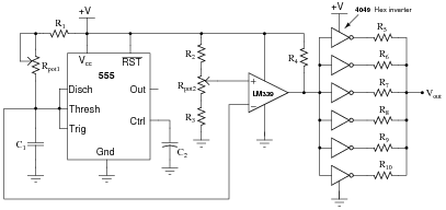
Here, six CMOS inverters (IC part number 4049) are ganged together in parallel to supply significantly more sourcing and sinking current capability than the LM339-with-pullup-resistor could on its own. Since CMOS logic gates are inherently on-or-off devices, they have no trouble handling the square wave output of the LM339.
Two questions here: first, why all the resistors at the outputs of the inverter gates? Why not just connect all the inverter outputs directly in parallel? Secondly, what value of resistor would you suggest at the output of each gate (R5 through R10)?

Two questions here: first, why all the resistors at the outputs of the inverter gates? Why not just connect all the inverter outputs directly in parallel? Secondly, what value of resistor would you suggest at the output of each gate (R5 through R10)?
Challenge question: adding inverter gates to the output of this circuit has an interesting effect on the duty cycle control. The potentiometer will now act backward from the way it was before (decreasing duty cycle when it formerly increased duty cycle, and visa-versa). Explain why.
Notes:
This question may or may not be suitable for your students, depending on whether or not they have studied logic gates yet. If they have not yet studied digital circuits, it may be wise to skip this question!
Note that I did not answer the question of resistor sizes. Discuss this with your students, and let them determine how these resistors should be sized. Let them have access to datasheets for the 4049 inverter IC, and ask them what parameter(s) would be the most important in this decision.
If no one notices, point out how the power supply wires are drawn for the six-gate (hex) inverter. This is a common way to show power wiring for multiple gates (or opamps, or any other sort of IC where complex elements are duplicated).


