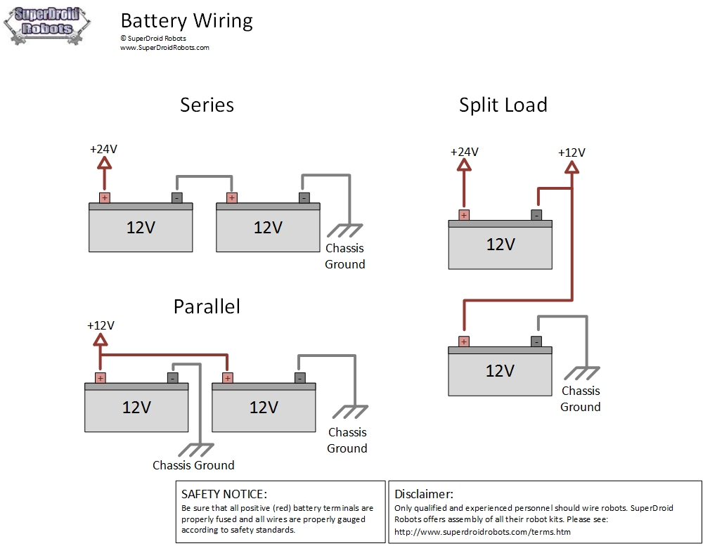
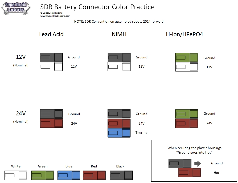
The important thing to consider is what the voltage that we need and how much force driving force for the main battery will be the motor. Preferably and usually using 24VDC motors, they run at half current for the same power as a 12V motors so small cable, motor controllers, and others, Do we need a separate battery for the controller or on-board computer, etc. How are we going to get them voltage (some batteries, voltage regulators, etc.). How much of the burden will be at each voltage so that our batteries and / or regulator is sized properly. This will help us measure our batteries. Simple math, if we have a load 1Amp 9 can to load audio and video also motor control) and battery 10Ahr (10,000mAhr), the battery will run for 10 hours in theory.
Required installation of fuses, It was great to put in the whole place to protect the components, but it is not always necessary. Many foreign exchange has built in overload protection such as switching regulators, smart battery packs, etc. If we are going to put a fuse in robotic equipment, it should be as close to the battery as possible.
The cornerstone principle of thinking and working is very important. land and a good place is important to protect the robot components and electrical noise. Preferably and usually placing a single ground lug to the aluminum chassis robot. All ground leads come to the same point. we do not want some runway locations to avoid some of the ground lines / potential, which will cause all sorts of problems that can not be explained. Treatment (track robot both SWOT = strengthness, Weakness, Opportunity and threatness; to track actuating and controlling robots; so getting the robot's motion appropriate dynamic standard operating procedure (SOP)) must be taken to ensure some reason did not run into the same piece of equipment , (This is most common with the motor controller, the incoming signal typically carries the signal ground as is the power to the motor controller, this results in a potential ground loops, signal ground should not normally be used, are gaining ground from power.
Motor Electric Hookup
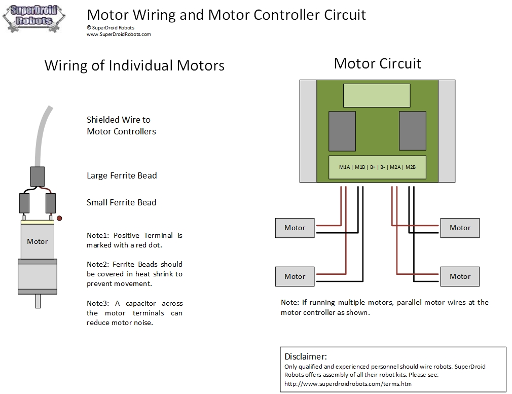
electrical noise is one of the most frustrating problems when working on a robot with a DC motor. EMF comes from the motor will produce a catastrophe on a microcontroller, RF equipment, or other sensitive electronic equipment. Should we use the following kit to wire your motor. This kit will provide a cable of speed / motor controller to the motor. we will need one kit per motor.
Wiring motors for robots
introduction
When using electric motor, one of the most important things to consider is the noise of the motor. robot motor cable should provide protection and help break down most of the noise of the motor is turned off. There are many lessons thoughts on how to control noise, Below is what it has been found to be the best practice to suppress motor noise.
The use of filter capacitors
A capacitor is a storage device voltage. They are often used to reduce the noise by smoothing the voltage waveform. The size of the capacitors are placed in series robot is of utmost importance in certain applications. did find that anything larger than 1uF will not make much difference in motor performance. where it is suggested to employ a capacitor filter is:
a.Di across the motor terminals. Take one or two non capacitor polarity sensitive and bridging two motor terminals.
the motor terminals to the motor home. Scratching off place between two motor terminals in the motor housing. Then solder capacitors from this location for each motor terminal.
b.Motor Controller. If you are building your own motor controller, make sure that there is a filter capacitor at the output of motor. If you use an off-the-shelf motor controller circuit filter capacitor is enough to have been implemented and additional filter circuits that are not needed and will not produce a noticeable difference.
c.kabel shielded; Every time you connect the device to a noisy or if you need to run cables close to noisy devices, it is always recommended to use shielded cable. shielded cable helps reduce the amount of noise is absorbed through the cable run.
d. Ferrite Beads; ferrite beads are often used in electronics to reduce electromagnetic interference (EMI). long conductive wires may act as antennas and radio frequency energy generating and adding a ferrite bead to the antenna is very helpful to solve EMI fields generated by wires. When using ferrite beads on the wire is recommended to use heat shrink the minimum size that will fit around.
Approximately every input motor. When using a shielded cable to connect to the motor you will need to expose a few inches of each cable to interface with the motor. A combination of heat shrink and ferrite beads will help reduce the amount of noise leaking into your cable from the motor.
Around the main cable. Attach a ferrite bead on the main cable will act as a barrier both to reduce noise.
additional recommendations
e. Check the ground loop
What we measure is the voltage of the electrical potential difference between two points, usually with one being ground. Having multiple paths to ground will make some noise for their reference point.
f. Do not run a parallel line
The best shielded cable as discussed above. Also it is important to try to keep the signal lines and power lines separately and try to run perpendicular. Rotate the positive and negative power lines together is also a good practice to keep the noise down (placing wires in an electric drill is a good trick to play fast cable and twist tight either.
g. Some cable Motors
When several motor cables to the motor controller single channel always make sure to run a wire from each terminal directly to the motor output of the motor controller us. Several motors can be run in parallel with the motor controller. namely 6WD robot with 6 motor will have 3 motors left running in parallel to one side of the motor controller, 3 the right motor will run in parallel to the other side of the motor controller. Sometimes when running multiple motors in parallel, the capacitor can cause errors with the motor controller, in this case trying to remove the capacitors from one motor at a time until the motor controller stops erroring.
h. Isolating Power Supplies
Having a separate source of power to the motor and the rest of your electronics will isolate and minimize the effects of your electronic motor noise.
For most wheeled robot applications, it is desirable to have more than two motors. To minimize the motor noise is advisable to run a shielded cable from each individual motor to the motor controller us. For example, if we have two motors per side, the positive cable (red) motor on the left will either go to a motorized cable M1A terminal while positive on the right side of the robot will go into M2A. Please see the pictures below for more details.
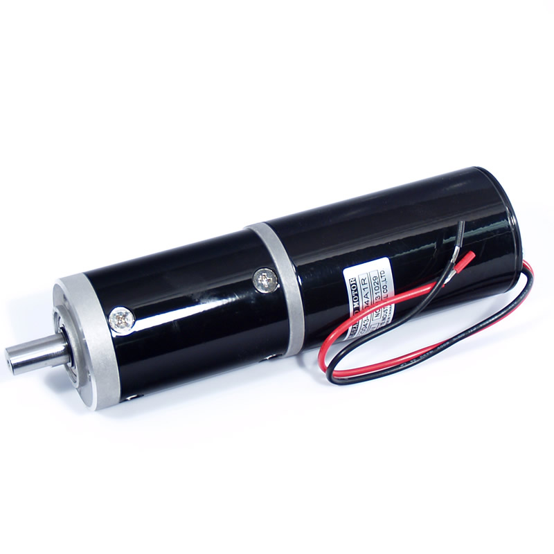
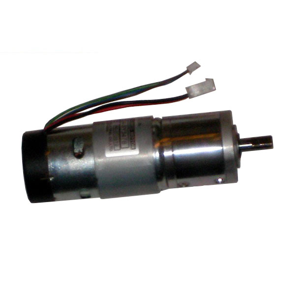

Stepper Motor and Controller Support
Unlike DC motors standards you apply a voltage and will move continuously in one direction, the stepper motor has two sets of inputs that allow it to pulse with the addition of a particular to control the exact position of the motor without sensor feedback as hall-effect or optical encoders ,
stepper motors are able to achieve this thanks to a few? toothed? electromagnets arranged around a piece of iron shaped teeth. When the driver stepper motors mounted to enable a set of rolls and drops the other, the motor will turn to align to the set is turned on. Each of these movements is called? Step?, Hence the name? Motorcycle.? To hold the motor in place, the second set of windings activated. To move in the opposite direction reversed sequence set rolls.
This means that the stepper motor will require a special motorcycle driver for it to operate properly.

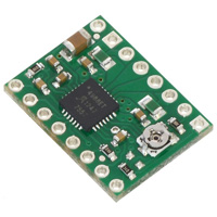
For example, we want to control 3.9 V, 600 mA bipolar stepper motors like this, but the A4988 stepper motor driver carrier you have a minimum operating voltage of 8 V. Can I use this driver without damaging the stepper motor?
Anticipation To avoid motor damage our steps, we want to avoid exceeding the current rating, which is 600 mA in this case. A4988 stepper motor driver let us limit the maximum current, so long as we set a lower limit value of the current, we will be within the specification for our motor, even if the voltage exceeds the rated voltage. The voltage rating is just the stress at which each coil exciting current value, so that the stepper motor coil we will draw 600 mA at 3.9 V. By using a higher voltage with an active current limit, which is currently able to increase faster , which allow us to reach levels higher step than we can use voltage.
How do we connect the stepper motor to the A4983 or A4988 stepper motor driver carrier?
The answer to this question depends on the type of step motor that we have. When working with a stepper motor, we will generally find two types: stepper motor unipolar and bipolar stepper motors. unipolar motor has two windings per phase, allowing the magnetic field to be reversed without reversing the direction of current in the coil, which makes the bike easier to control unipolar from bipolar stepper motors. The drawback is that only half of the phases that carry current at a certain time, which lowers the torque you can get out of the stepper motor. However, if we have a proper control circuit, we can improve the torque stepper motors using unipolar stepper motors as bipolar stepper motors (note: this is only possible with 6- or 8-lead unipolar stepper motors, not with 5- cause unipolar stepper motors ). unipolar stepper motors usually have five, six, or eight leads.
bipolar steppers have a single coil per phase and require more complex control circuit (usually H-bridge for each phase). The A4983 and A4988 have the circuitry required to control bipolar stepper motors. bipolar stepper motors usually have four leads, two for each coil.
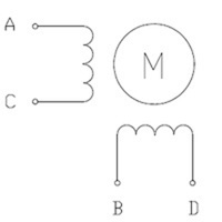
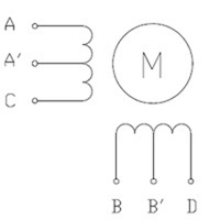
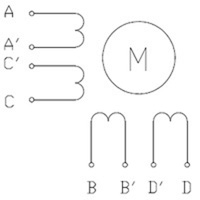
(1 ) (2) (3)
(1) Two-phase bipolar stepper motor with four leads.
The diagram above shows the standard bipolar stepper motor. To control this with the A4983 or A4988, connecting stepper lead A to ride 1A output, stepper led to rising output C 1B, stepper led to rising output B 2A, and stepper led to rising output D 2B. See datasheet A4983 / A4988 for more information.
(2) Two-phase unipolar stepper motors with six leads.
You can connect it to the A4983 or A4988 as bipolar stepper motors with bipolar described making connections at the top and left stepper leads A? and B? disconnected. This leads to the center tap of the two coils and is not used for bipolar operation.
(3) Two-phase unipolar stepper motors with eight leads.
we have several connection options. A unipolar stepper motors eight lead has two coils per phase, and gives you access to all of the lead coil (motor unipolar six leads, leads the A? Internal connected to C? And lead B? Internal connected to D?). When operating as a bipolar stepper, you have the option of using two coils for each phase in parallel or series. When using them in parallel, if it reduces the coil inductance, which can lead to improved performance if we have the ability to provide more current. However, since the A4983 and A4988 Active limiting output current per phase, we will only get half of the phase currents flowing through each of the two coils in parallel. When using them in the series, is it? S like having a single coil per phase (as in a four-lead steppers bipolar or unipolar steppers used six lead as bipolar steppers). We suggest we use the serial connection.
To connect the phase coils in parallel, connect stepper leads A and C? to ride 1A output, stepper leads A? and C to ride 1B output, stepper lead B and D? 2A output to rise, and stepper point B? and D for rising output 2B.
To connect the phase coils in series, connecting the lead stepper A? to C? and stepper lead B? to D?. Stepper leads A, C, B, and D must be connected to a stepper motor driver as usual for bipolar stepper motors (see connections bipolar stepper above).
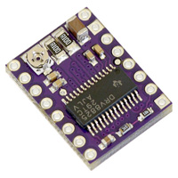
we want to control 3.9 V, 600 mA bipolar stepper motors like this, but DRV8825 stepper motor driver operator you have a minimum operating voltage of 8.2 V. Can I use this driver without damaging the stepper motor?
To avoid motor damage your step, you want to avoid exceeding the current rating, which is 600 mA in this case. DRV8825 stepper motor drivers that let you limit the maximum current, so long as you set a lower limit value of the stream, you'll be within specifications for your bike, even if the voltage exceeds the rated voltage. The voltage rating is just the stress at which each coil exciting current value, so that your stepper motor coil will draw 600 mA at 3.9 V. By using a higher voltage with an active current limit, which is currently able to increase faster , which lets you reach a level higher than the steps you can use a voltage.
I DRV8825 stepper motor drivers too hot but my electric show it? S draw significantly less than 1.5 A per coil. What gives?
Measure the current draw on the power supply does not always provide an accurate measure of the coil current. Because the input voltage to the driver can be significantly higher than the coil voltage, measured current in the power supply can be quite a bit lower than the coil current (coil driver and basically acts like a switching power supply step-down). Also, if the supply voltage is very high compared to what you need the motor to achieve the set at this time, the cycle will be very low, which also causes a significant difference between the average and RMS currents: RMS current on what's relevant to the power dissipation in the chip but many power supplies to win? t show that. You should base your assessment of the coil current at the current limit set or by measuring the actual coil current.
Please note that while DRV8825 driver IC is rated up to 2.5 A per coil, 0.5 W current sense resistor is only rated for 2.2 A, and the chip itself will overheat at low currents. We have found that generally require a heat sink to provide more than about 1.5 A per coil, but this number depends on factors such as temperature and air flow. For example, sealing the three carriers near DRV8825 driver in a small box will cause them to become too hot at low currents of the unit by itself in the open air.
How do I connect my stepper motor to DRV8824 or DRV8825 stepper motor driver operator?
The answer to this question depends on the type of stepper motor you have. When working with a stepper motor, you will usually find two types: stepper motor unipolar and bipolar stepper motors. unipolar motor has two windings per phase, allowing the magnetic field to be reversed without reversing the direction of current in the coil, which makes the bike easier to control unipolar from bipolar stepper motors. The drawback is that only half of the phases that carry current at a certain time, which lowers the torque you can get out of the stepper motor. However, if you have the appropriate control circuitry, you can increase the torque stepper motors using unipolar stepper motors as bipolar stepper motors (note: this is only possible with 6- or 8-lead unipolar stepper motors, not with 5- cause unipolar stepper motors ). unipolar stepper motors usually have five, six, or eight leads.
bipolar steppers have a single coil per phase and require more complex control circuit (usually H-bridge for each phase). The DRV8824 / DRV8825 have the circuitry required to control bipolar stepper motors. bipolar stepper motors usually have four leads, two for each coil.


( 1 ) (2) (3)
Motor controller
What is a motor controller?
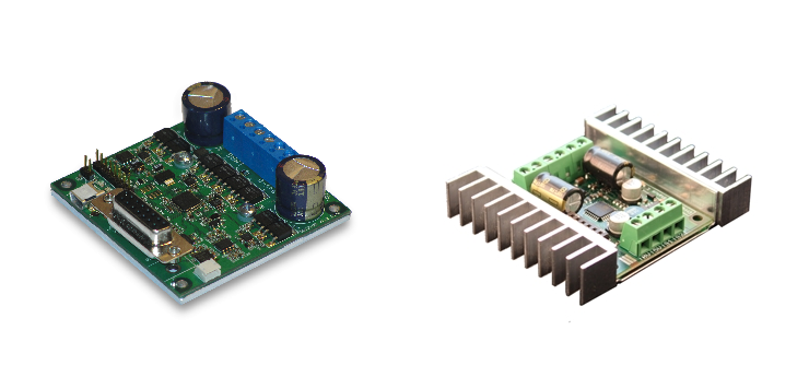
A motor controller picks up the signal input low voltage and low current drive motor with higher voltage and current. The input signal can be serial, I2C, RC input, PWM, etc. Below are the various types of motor controller () with a brief description of each. For full details of each motor controller to go to the item page. Each page has a link item motor controller support for data sheets, manuals, etc.
How to Work a motor controller
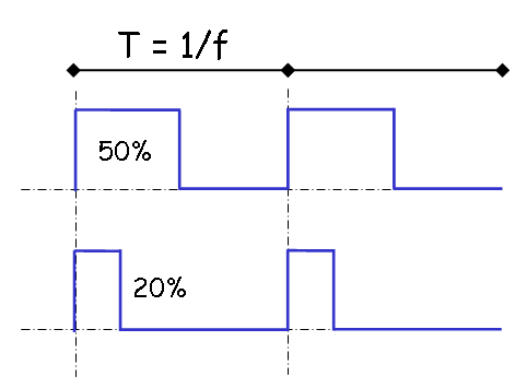
The output of the PWM-based motor controller, which stands for pulse width modulation. The concept of PWM signal output power is to switch on and off really quickly to reduce the average voltage applied to the motor to precisely control motor speed
Wire Crimping Support
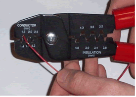
Cable to many sensors require curly Trekker needs to be installed so that the sensor can plug right into the Trekker OOPic Expansion Board. Some sensors require wires soldered to them.
If we want, we can choose the addition (s) to have SuperDroid Robot crimp, solder or both of us. If crimping chosen as an extra, we do not need to do anything crimping. If the solder is selected, we do not need to solder anything.
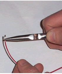
crimping is done by using a crimping tool, or can be done using a needle nosed pliers according to the image below.

soldering techniques
Solder is the process of manufacture of electrical and mechanical joint between the metal sound certain to join them with a soft solder. This is a low-temperature melting point alloy of lead and tin. the joint is heated to the correct temperature by soldering iron. For most electronic working miniature solder-powered aircraft used. It consists of a handle attached to the heating element. At the end of the heating element is what is known as a "bit", so called because it is a bit of warming up the joints. Solder melts at about 190 degrees Celsius, and little reaches temperatures of over 250 degrees Celsius. The temperature was plenty hot enough to cause burns evil, consequently care should be taken.
It is also easy to burn through the insulation on the leads PVC soldering iron if you were to put a little heat on it. It is prudent, therefore, to use a specially designed stand solder. It usually incorporates a sponge to keep a little cleaner.
solder come with different ratings from 15W to over 100W. The advantage of high-wattage iron is that heat can flow quickly into the joint, so it can be quickly made. This is important when soldering the connector as often as there is quite a large volume of metal to be heated. A small iron will require more time to heat the joints to the correct temperature, during which time there is a danger of being damaged insulation. A small metal used to make the joints with small electronic components are easily damaged by excessive heat.
Always use a good quality multicore solder. A standard 60% tin, 40% lead solder alloys with non-corrosive flux core will be found easiest to use. The flux is contained in the core longitudinal Multicore solder are chemicals designed to clean surfaces to be joined oxide deposited, and to exclude the air during the soldering process, which will not prevent this metal come together. As a result, do not expect to be able to complete with the use of the application of the iron tip is loaded with molten solder, because this usually will not work. Having said that, there is a process called tinning where the first conductor coated in a fresh, new solder before joining with a hot iron. Solder comes in gauges like wire. The two most common are 18 SWG, used for public works, and the thinner 22 SWG, used to work well on the printed circuit board.

ROBO'S

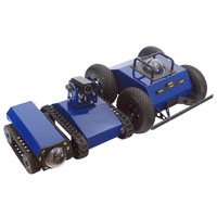
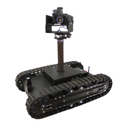
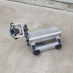
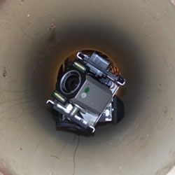
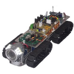
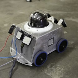
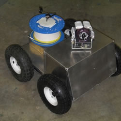
Equipped with cameras, these robots are made to inspect tight spaces. They go everywhere you can't (or won't) go: under houses, inside ducts, down sewers and through culverts and pipes.
|
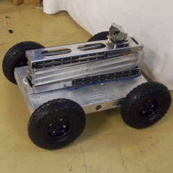
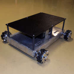
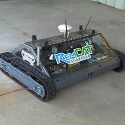
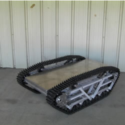
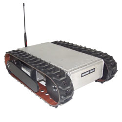
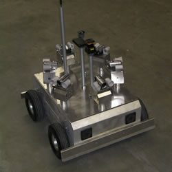
Robot kits that have tracks, standard wheels, omni wheels, or mecanum wheels. All these kits are designed and built by SuperDroid Robots in North Carolina, USA. We offer different sizes and configurations for all budgets and needs.
|
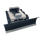
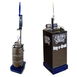
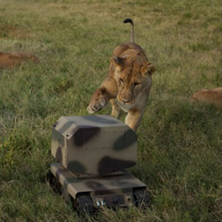
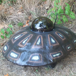
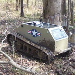
These are specialized robots that are purpose built. The robots are built for a specialized purpose. Use these robots to cut the yard, plow the snow, pour yourself a beer, etc.
| |
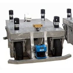
Programable Robots. Autonomous Robots. Robots that think on their own and do set tasks. They range from customized Arduino WiFi robots to programmable tactical robots.
|
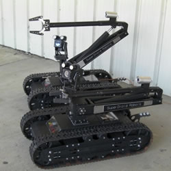
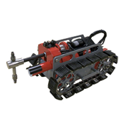
Tactical Robots, EOD Robots, SWAT Robots, Law Enforcement Robots, Military Robots, Surveillance Robots, UGV's, Security Robots can be found here in this area of the site.
|
Remote presence 2-way (RP2W) Robots help make video conferencing mobile. Drive your robot around remotely from anywhere in the world, your face is displayed on the robot and you control the robot's camera to view everything remotely.
|
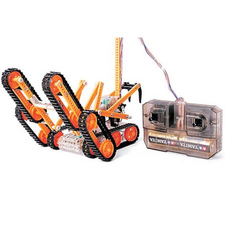
Tamiya kits are fun, inexpensive kits you can build to begin learning about robotics and mechanical gears.
|
Robotic Arms for mobile Robots from hobbyist to tactical robots. The LT2 and HD2 Arms have been in service on our tactical robots for many years. If you don't see it, check out our custom robot design services!
|
Patrol your property and checkup on things. Control these robots through your local Wi-Fi Network via your desktop, laptop, or tablet computer. SuperDroid Robots provides a custom control package that makes controlling the robot easy.
|
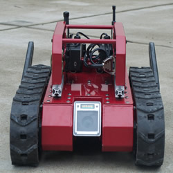
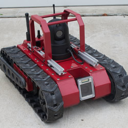
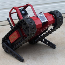
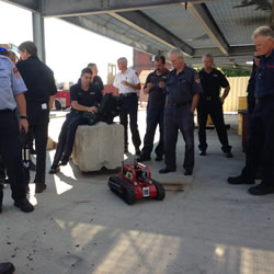
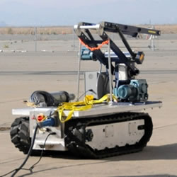
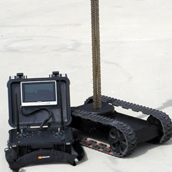
Tactical Robot is built specifically to provide video and audio surveillance to hazardous situations / dangerous to keep people out of harms way, or play with a situation of extreme nature, the application of robot tactical usual for Police, Fire, Rescue, Military, and keep certain areas.
Electrical Robot Components and Robot Controls

Get great prices on robot batteries and robot battery accessories. We carry NiMH batteries, battery packs, and chargers for your robotic applications.
|
Ethernet equipment, Wireless Routers and Network Cards including antennas, cables, cameras, and more for a complete network solution!
|
These items can be used with your Arduino, mBed, Basic Micro, or any other microcontroller platform.
|
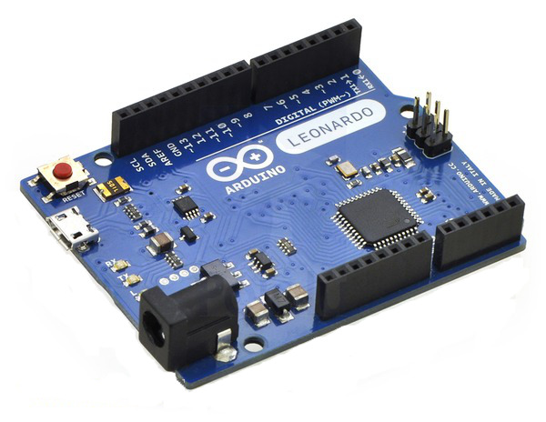
We offer both PIC and AVR microcontrollers. Choose from our selection of authentic Arduino controllers and shields, Basic controllers, and ARM microcontrollers.
|
Cameras and AV Equipment such as LCD, Cables, Quads, etc. for Robots or what ever other use you may have for cameras.
|
We offer a range of remote controllers and RC accessories, including RC switches and Spektrum remotes.
|
We offer a variety of battery chargers, transformers, and power supplies. We feature lead acid chargers, Li-ion chargers, NiMH chargers, and NiCad chargers.
|
We offer multiple ways to convert RS232. We have 3-5V TTL converter cables, RS232 to USB, Ethernet converters, and USB to TTL converters.
|
Ribbon Cables, wire jumpers, Ethernet, RCA, BNC, RS232, etc for connecting your electronics together.
|
We have sensors to help you detect gasses, conduct surveillance, and measure performance. These sensors can help toward building an autonomous robot.
|
Discrete Components including High Current Drivers, Swithes, Relays, Fuses, Breakers, Etc.
|
These controllers and related items are used to control/drive hobby RC servos and Dynamixel Servos by Robotis.
|
We offer a wide range of IG32 (32mm), IG42 (42mm), and IG52 (52mm) motors with encoders, motor controllers with encoder feedback and breakout boards to interface a microcontroller board directly to the encoder.
| |
Joysticks for making your own control system. We use these same joysticks in our control Systems.
|
Wiring and hook-up kits to help you wire up your next project. This includes wire, power cables, crimps, headers, etc
|
Data LCDs for you microcontrollers, Color LCDs for your AV Cameras, and accessories.
|
We offer a variety of methods for wireless robotic control methods. From WiFi to RC, to xBee and Zigbee. The go-to method for basic wireless control is Radio Control (RC). We carry a wide variety of RC transmitters and receivers.
|
Motor speed controllers (PWM) to control your DC motors with a RC system or microcontroller.
|
Mechanical Robot Parts
Anything and everything mechanical needed for robot building is found here. We have gear motors, servos, wheels, tank treads, hardware packages, and more.
We carry flanged double sealed, steel ball bearings. These bearings help keep the dirt out and the oil in, resulting in a durable part and long lifespan.
|
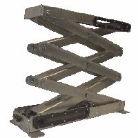
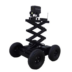
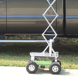
These electric scissor lifts are perfect for surveillance and other applications requiring a camera system. Some of these items are specifically built to fit our 360 pan/tilt systems.
|
Pan and Tilt Systems for cameras. These pan and tilt system allow you to move your camera view left and right and up and down.
| |
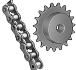
We offer ANSI #25 and #35 roller chain and steel finished roller chain sprockets. The sprockets are available by the number of teeth as well as the bore size.
| |
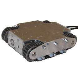
Mechanical robot chassis. ATR Robots of every size for every purpose. SuperDroid Robots makes all their robot kits in North Carolina USA.
|
We carry zinc coated steel shaft collars. These collars help lock your shafts into place.
|
A wide variety of DC gear motors for driving your robots. We carry IG32, IG42, IG52, IG90, and wheelchair motors.
|
Stepper motors are generally used in a variety of applications where precise position control is desirable and the cost or complexity of a feedback control system is unwarranted.
|
We offer a wide range of durable tank treads and tracks that can be used for tanks, robots, and other vehichles. Get the tank treads and tracks you need.
| |
Hardware to put your robot kits together. Hard to find small hardware packages complete with nylon spacers, etc.
|
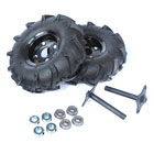
Wheels for your robot application. Big and small along with omni directional wheels.
|
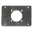
These are the motor plates and machined tubes that we use when mounting motors in our robots.
|
Specialized Robots
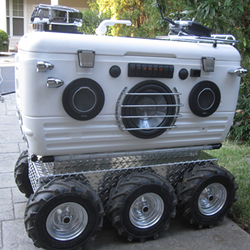
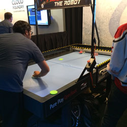
Who says that robots have to be all work and no play? We specialize in robotic solutions for the home with our snow removal robots, remote controlled lawnmowers and even a robotic cooler to provide you with refreshment and entertainment. Click on the images below to see what we're capable of building.
