Wind turbine
A wind turbine is a device that converts the wind's kinetic energy into electrical energy.
Wind turbines are manufactured in a wide range of vertical and horizontal axis types. The smallest turbines are used for applications such as battery charging for auxiliary power for boats or caravans or to power traffic warning signs. Slightly larger turbines can be used for making contributions to a domestic power supply while selling unused power back to the utility supplier via the electrical grid. Arrays of large turbines, known as wind farms, are becoming an increasingly important source of intermittent renewable energy and are used by many countries as part of a strategy to reduce their reliance on fossil fuels.
.jpg)
Wind power was probably used in Persia (present-day Iran) about 500–900 AD.[1] The windwheel of Hero of Alexandria marks one of the first recorded instances of wind powering a machine in history.[2][3] However, the first known practical wind power plants were built in Sistan, an Eastern province of Iran, from the 7th century. These "Panemone" were vertical axle windmills, which had long vertical drive shafts with rectangular blades.[4] Made of six to twelve sails covered in reed matting or cloth material, these windmills were used to grind grain or draw up water, and were used in the gristmilling and sugarcane industries.[5]
Wind power first appeared in Europe during the Middle Ages. The first historical records of their use in England date to the 11th or 12th centuries and there are reports of German crusaders taking their windmill-making skills to Syria around 1190.[6] By the 14th century, Dutch windmills were in use to drain areas of the Rhine delta. Advanced wind turbines were described by Croatian inventor Fausto Veranzio. In his book Machinae Novae (1595) he described vertical axis wind turbines with curved or V-shaped blades.
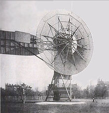
The first electricity-generating wind turbine was a battery charging machine installed in July 1887 by Scottish academic James Blyth to light his holiday home in Marykirk, Scotland.[7] Some months later American inventor Charles F. Brush was able to build the first automatically operated wind turbine after consulting local University professors and colleagues Jacob S. Gibbs and Brinsley Coleberd and successfully getting the blueprints peer-reviewed for electricity production in Cleveland, Ohio.Although Blyth's turbine was considered uneconomical in the United Kingdom electricity generation by wind turbines was more cost effective in countries with widely scattered populations.
 In Denmark by 1900, there were about 2500 windmills for mechanical loads such as pumps and mills, producing an estimated combined peak power of about 30 MW. The largest machines were on 24-meter (79 ft) towers with four-bladed 23-meter (75 ft) diameter rotors. By 1908 there were 72 wind-driven electric generators operating in the United States from 5 kW to 25 kW. Around the time of World War I, American windmill makers were producing 100,000 farm windmills each year, mostly for water-pumping.[9]
By the 1930s, wind generators for electricity were common on farms, mostly in the United States where distribution systems had not yet been installed. In this period, high-tensile steel was cheap, and the generators were placed atop prefabricated open steel lattice towers.
A forerunner of modern horizontal-axis wind generators was in service at Yalta, USSR in 1931. This was a 100 kW generator on a 30-meter (98 ft) tower, connected to the local 6.3 kV distribution system. It was reported to have an annual capacity factor of 32 percent, not much different from current wind machines.[10]
In the autumn of 1941, the first megawatt-class wind turbine was synchronized to a utility grid in Vermont. The Smith-Putnam wind turbine only ran for 1,100 hours before suffering a critical failure. The unit was not repaired, because of shortage of materials during the war.
The first utility grid-connected wind turbine to operate in the UK was built by John Brown & Company in 1951 in the Orkney Islands.[7][11]
Despite these diverse developments, developments in fossil fuel systems almost entirely eliminated any wind turbine systems larger than supermicro size. In the early 1970s, however, anti-nuclear protests in Denmark spurred artisan mechanics to develop microturbines of 22 kW. Organizing owners into associations and co-operatives lead to the lobbying of the government and utilities and provided incentives for larger turbines throughout the 1980s and later. Local activists in Germany, nascent turbine manufacturers in Spain, and large investors in the United States in the early 1990s then lobbied for policies that stimulated the industry in those countries. Later companies formed in India and China. As of 2012, Danish company Vestas is the world's biggest wind-turbine manufacturer.
Wind turbines are classified by the wind speed they are designed for, from class I to class IV, with A or B referring to the turbulence.
The maximum theoretical power output of a wind machine is thus 16/27 times the kinetic energy of the air passing through the effective disk area of the machine. If the effective area of the disk is A, and the wind velocity v, the maximum theoretical power output P is:
As wind is free (no fuel cost), wind-to-rotor efficiency (including rotor blade friction and drag) is one of many aspects impacting the final price of wind power.[15] Further inefficiencies, such as gearbox losses, generator and converter losses, reduce the power delivered by a wind turbine. To protect components from undue wear, extracted power is held constant above the rated operating speed as theoretical power increases at the cube of wind speed, further reducing theoretical efficiency. In 2001, commercial utility-connected turbines deliver 75% to 80% of the Betz limit of power extractable from the wind, at rated operating speed.
Efficiency can decrease slightly over time due to wear. Analysis of 3128 wind turbines older than 10 years in Denmark showed that half of the turbines had no decrease, while the other half saw a production decrease of 1.2% per year.[18] Vertical turbine designs have much lower efficiency than standard horizontal designs.
 Wind turbines can rotate about either a horizontal or a vertical axis, the former being both older and more common.[20] They can also include blades (transparent or not)[21] or be bladeless. Vertical designs produce less power and are less common.
Horizontal-axis wind turbines (HAWT) have the main rotor shaft and electrical generator at the top of a tower, and must be pointed into the wind. Small turbines are pointed by a simple wind vane, while large turbines generally use a wind sensor coupled with a servomotor. Most have a gearbox, which turns the slow rotation of the blades into a quicker rotation that is more suitable to drive an electrical generator.[24]
Any solid object produces a wake behind it, leading to fatigue failures, so the turbine is usually positioned upwind of its supporting tower. Downwind machines have been built, because they don't need an additional mechanism for keeping them in line with the wind. In high winds, the blades can also be allowed to bend which reduces their swept area and thus their wind resistance. In upwind designs, turbine blades must be made stiff to prevent the blades from being pushed into the tower by high winds. Additionally, the blades are placed a considerable distance in front of the tower and are sometimes tilted forward into the wind a small amount.
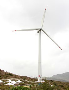
Turbines used in wind farms for commercial production of electric power are usually three-bladed. These have low torque ripple, which contributes to good reliability. The blades are usually colored white for daytime visibility by aircraft and range in length from 20 to 80 meters (66 to 262 ft). The size and height of turbines increase year by year. Offshore wind turbines are built up to 8MW today and have a blade length up to 80m. Usual tubular steel towers of multi megawatt turbines have a height of 70 m to 120 m and in extremes up to 160 m.
The blades rotate at 10 to 22 revolutions per minute. At 22 rotations per minute the tip speed exceeds 90 meters per second (300 ft/s). Higher tip speeds means more noise and blade erosion. A gear box is commonly used for stepping up the speed of the generator, although designs may also use direct drive of an annular generator. Some models operate at constant speed, but more energy can be collected by variable-speed turbines which use a solid-state power converter to interface to the transmission system. All turbines are equipped with protective features to avoid damage at high wind speeds, by feathering the blades into the wind which ceases their rotation, supplemented by brakes.
Vertical-axis wind turbines (or VAWTs) have the main rotor shaft arranged vertically. One advantage of this arrangement is that the turbine does not need to be pointed into the wind to be effective, which is an advantage on a site where the wind direction is highly variable. It is also an advantage when the turbine is integrated into a building because it is inherently less steerable. Also, the generator and gearbox can be placed near the ground, using a direct drive from the rotor assembly to the ground-based gearbox, improving accessibility for maintenance. However, these designs produce much less energy averaged over time, which is a major drawback.[23][27]
The key disadvantages include the relatively low rotational speed with the consequential higher torque and hence higher cost of the drive train, the inherently lower power coefficient, the 360-degree rotation of the aerofoil within the wind flow during each cycle and hence the highly dynamic loading on the blade, the pulsating torque generated by some rotor designs on the drive train, and the difficulty of modelling the wind flow accurately and hence the challenges of analysing and designing the rotor prior to fabricating a prototype.[28]
When a turbine is mounted on a rooftop the building generally redirects wind over the roof and this can double the wind speed at the turbine. If the height of a rooftop mounted turbine tower is approximately 50% of the building height it is near the optimum for maximum wind energy and minimum wind turbulence. Wind speeds within the built environment are generally much lower than at exposed rural sites, noise may be a concern and an existing structure may not adequately resist the additional stress.
Subtypes of the vertical axis design include:
Darrieus wind turbine
"Eggbeater" turbines, or Darrieus turbines, were named after the French inventor, Georges Darrieus.[31] They have good efficiency, but produce large torque ripple and cyclical stress on the tower, which contributes to poor reliability. They also generally require some external power source, or an additional Savonius rotor to start turning, because the starting torque is very low. The torque ripple is reduced by using three or more blades which results in greater solidity of the rotor. Solidity is measured by blade area divided by the rotor area. Newer Darrieus type turbines are not held up by guy-wires but have an external superstructure connected to the top bearing.[32]
Giromill
A subtype of Darrieus turbine with straight, as opposed to curved, blades. The cycloturbine variety has variable pitch to reduce the torque pulsation and is self-starting.[33] The advantages of variable pitch are: high starting torque; a wide, relatively flat torque curve; a higher coefficient of performance; more efficient operation in turbulent winds; and a lower blade speed ratio which lowers blade bending stresses. Straight, V, or curved blades may be used.[34]
Savonius wind turbine
These are drag-type devices with two (or more) scoops that are used in anemometers, Flettner vents (commonly seen on bus and van roofs), and in some high-reliability low-efficiency power turbines. They are always self-starting if there are at least three scoops.
Twisted Savonius
Twisted Savonius is a modified savonius, with long helical scoops to provide smooth torque. This is often used as a rooftop windturbine and has even been adapted for ships. Another type of vertical axis is the Parallel turbine, which is similar to the crossflow fan or centrifugal fan. It uses the ground effect. Vertical axis turbines of this type have been tried for many years: a unit producing 10 kW was built by Israeli wind pioneer Bruce Brill in the 1980s
Wind turbines convert wind energy to electricity for distribution. Conventional horizontal axis turbines can be divided into three components:
Among all renewable energy systems wind turbines have the highest effective intensity of power-harvesting surface because turbine blades not only harvest wind power, but also concentrate it.
 An E-66 wind turbine in the Windpark Holtriem, Germany, has an observation deck for visitors. Another turbine of the same type with an observation deck is located in Swaffham, England. Airborne wind turbine designs have been proposed and developed for many years but have yet to produce significant amounts of energy. In principle, wind turbines may also be used in conjunction with a large vertical solar updraft tower to extract the energy due to air heated by the sun.
Wind turbines which utilise the Magnus effect have been developed.
A ram air turbine (RAT) is a special kind of small turbine that is fitted to some aircraft. When deployed, the RAT is spun by the airstream going past the aircraft and can provide power for the most essential systems if there is a loss of all on-board electrical power, as in the case of the "Gimli Glider".
The two-bladed SCD 6MW offshore turbine designed by aerodyn Energiesysteme and built by MingYang Wind Power has a helideck for helicopters on top of its nacelle. The prototype was erected in 2014 in Rudong, China.
As competition in the wind market increases, companies are seeking ways to draw greater efficiency from their designs. One of the predominant ways wind turbines have gained performance is by increasing rotor diameters, and thus blade length. Retrofitting current turbines with larger blades mitigates the need and risks associated with a system-level redesign. By incorporating carbon fiber into parts of existing blade systems, manufacturers may increase the length of the blades without increasing their overall weight. For instance, the spar cap, a structural element of a turbine blade, commonly experiences high tensile loading, making it an ideal candidate to utilize the enhanced tensile properties of carbon fiber in comparison to glass fiber.[52] Higher stiffness and lower density translates to thinner, lighter blades offering equivalent performance. In a 10-MW turbine—which will become more common in offshore systems by 2021—blade lengths may reach over 100 m and weigh up to 50 metric tons when fabricated out of glass fiber. A switch to carbon fiber in the structural spar of the blade yields weight savings of 20 to 30 percent, or approximately 15 metric tons.[53] The compressive properties of carbon fiber do not differ significantly from those of glass fiber. It is therefore economical to replace glass fiber components under compression with carbon fiber components. Improving performance through weight reductions rather than increasing scale also has advantages in transportation. The size of a wind turbine, its blades and tower, are all limited by the height and width clearances, and turning radius, of the route used to transport the components to the installation site. The scale of these pieces has in some cases forced the adoption of Schnabel trailers.
While the material cost is significantly higher for all-glass fiber blades than for hybrid glass/carbon fiber blades, there is a potential for tremendous savings in manufacturing costs when labor price is considered. Utilizing carbon fiber enables for simpler designs that use less raw material. The chief manufacturing process in blade fabrication is the layering of plies. By reducing the number of layers of plies, as is enabled by thinner blade design, the cost of labor may be decreased, and in some cases, equate to the cost of labor for glass fiber blades.[54]
Materials for wind turbine parts other than the rotor blades (including the rotor hub, gearbox, frame, and tower) are largely composed of steel. Modern turbines uses a couple of tonnes of copper for generators, cables and such.[55] Smaller wind turbines have begun incorporating more aluminum based alloys into these components in an effort to make the turbines more lightweight and efficient, and may continue to be used increasingly if fatigue and strength properties can be improved. Prestressed concrete has been increasingly used for the material of the tower, but still, requires much reinforcing steel to meet the strength requirement of the turbine. Additionally, step-up gearboxes are being increasingly replaced with variable speed generators, increasing the demand for magnetic materials in wind turbines.,[50] In particular, this would require an increased supply of the rare earth metal neodymium. Reliance on rare earth minerals for components has risked expense and price volatility as China has been main producer of rare earth minerals (96% in 2009) and had been reducing its export quotas of these materials.[56] In recent years, however, other producers have increased production of rare earth minerals and China has removed its reduced export quota on rare earths leading to an increased supply and decreased cost of rare earth minerals, increasing the viability of the implementation of variable speed generators in wind turbines on a large scale.
 A few localities have exploited the attention-getting nature of wind turbines by placing them on public display, either with visitor centers around their bases, or with viewing areas farther away.The wind turbines are generally of conventional horizontal-axis, three-bladed design, and generate power to feed electrical grids, but they also serve the unconventional roles of technology demonstration, public relations, and education.
 Small wind turbines may be used for a variety of applications including on- or off-grid residences, telecom towers, offshore platforms, rural schools and clinics, remote monitoring and other purposes that require energy where there is no electric grid, or where the grid is unstable. Small wind turbines may be as small as a fifty-watt generator for boat or caravan use. Hybrid solar and wind powered units are increasingly being used for traffic signage, particularly in rural locations, as they avoid the need to lay long cables from the nearest mains connection point.[59] The U.S. Department of Energy's National Renewable Energy Laboratory (NREL) defines small wind turbines as those smaller than or equal to 100 kilowatts. Small units often have direct drive generators, direct current output, aeroelastic blades, lifetime bearings and use a vane to point into the wind.
Larger, more costly turbines generally have geared power trains, alternating current output, flaps and are actively pointed into the wind. Direct drive generators and aeroelastic blades for large wind turbines are being researched.
Modern turbines usually have a small onboard crane for hoisting maintenance tools and minor components. However, large heavy components like generator, gearbox, blades and so on are rarely replaced and a heavy lift external crane is needed in those cases. If the turbine has a difficult access road, a containerized crane can be lifted up by the internal crane to provide heavier lifting.
A demolition industry develops to recycle offshore turbines at a cost of DKK 2–4 million per MW, to be guaranteed by the owner.[70]
Wind turbines provide a clean energy source, emitting no greenhouse gases and no waste product. Over 1,500 tons of carbon dioxide per year can be eliminated by using a one megawatt turbine instead of one megawatt of energy from a fossil fuel. Being environmentally friendly and green is a large advantage of wind turbines.
Environmental impact of wind power includes effect on wildlife. Thousands of birds, including rare species, have been killed by the blades of wind turbines,[75] though wind turbines contribute relatively insignificantly to anthropogenic avian mortality. For every bird killed by a wind turbine in the US, nearly 500,000 are killed by each of feral cats and buildings.[76]. In comparison, conventional coal fired generators contribute significantly more to bird mortality, by incineration when caught in updrafts of smoke stacks and by poisoning with emissions byproducts (including particulates and heavy metals downwind of flue gases). Further, marine life is affected by water intakes of steam turbine cooling towers (heat exchangers) for nuclear and fossil fuel generators, by coal dust deposits in marine ecosystems (e.g. damaging Australia's Great Barrier Reef) and by water acidification from combustion monoxides.
Energy harnessed by wind turbines is intermittent, and is not a "dispatchable" source of power; its availability is based on whether the wind is blowing, not whether electricity is needed. Turbines can be placed on ridges or bluffs to maximize the access of wind they have, but this also limits the locations where they can be placed.[71] In this way, wind energy is not a particularly reliable source of energy. However, it can form part of the energy mix, which also includes power from other sources. Notably, the relative available output from wind and solar sources is often inversely proportional (balancing). Technology is also being developed to store excess energy, which can then make up for any deficits in supplies.


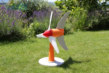
XXX . V The windpower Writer
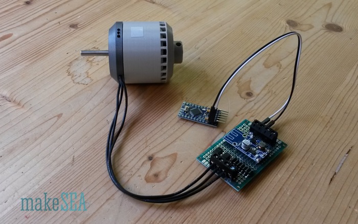
![]()
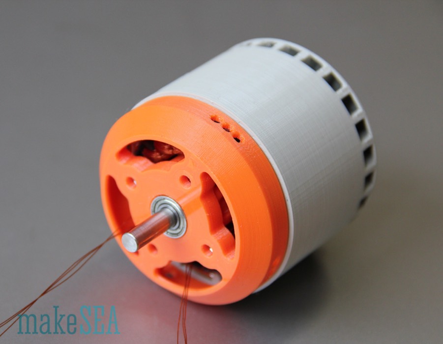
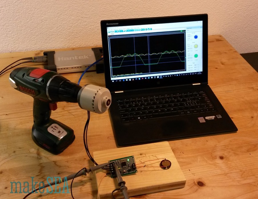
 However the subsequent design changes of the stator for the brushless motor allowed to decrease the number of turns (in favor for a larger cross-section and higher currents) while keeping the Kv almost unchanged. This means the Kv could be clearly reduced with the large number of turns and the thinner wire. Hence I reused the unchanged design of the stator from Model A001.1 as the stator for the generator. Initially I only wound a single coil, and measured with the drill and the scope its properties.
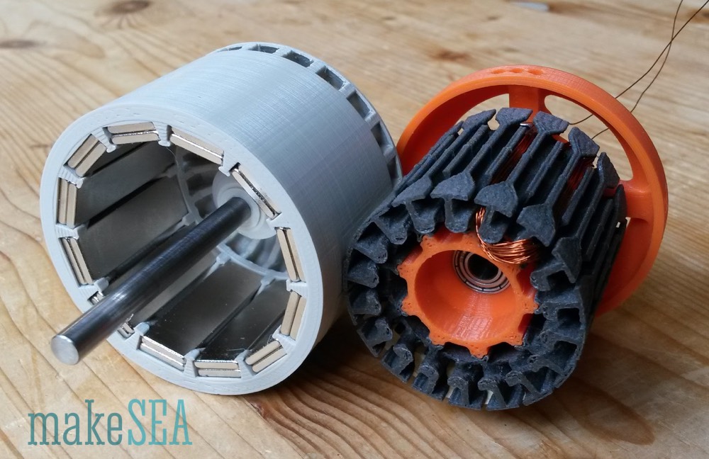
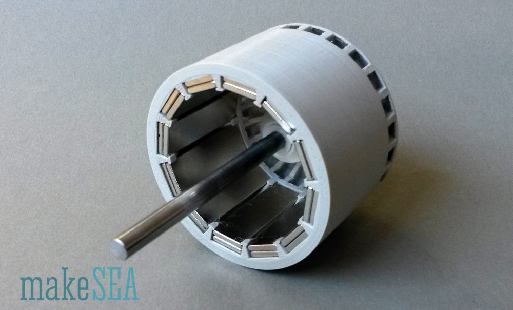
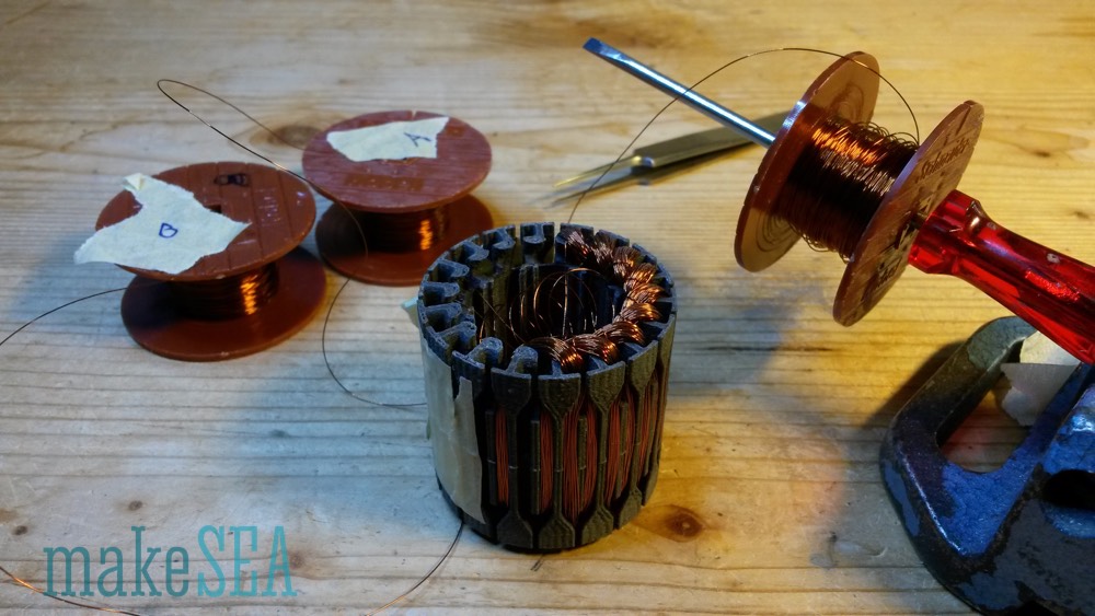
These results were very promising, so I continued with the stator winding (with 64 turns per coil, because 64 is a nicer number than 63). From the first coil, I could measure the weight of the used copper (knowing also the weight of the empty stator). It was 2.14 grammes. The complete generator has 6 coils per phase. For each of the 3 phases the copper wired needed to be wound on a temporary spool. Hence 6 times 2.14g = 6.84g copper wire per spool. Wrong! How embarrassing - I realized my calculation mistake in the middle of the winding work at 2:00am. I had to extend and solder these flimsy wires in the middle of the night. The finally needed copper per phase weights exactly 10.31g (measured). Without calculation mistake, the prepared spools would have been well suitable.
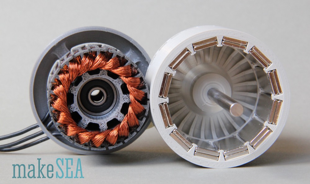
The finished stator has 3 * 6 * 64 = 1’152 turns. With 36 teeth it’s 32 turns per tooth. The generator is ready for extensive measurements and tough tests.
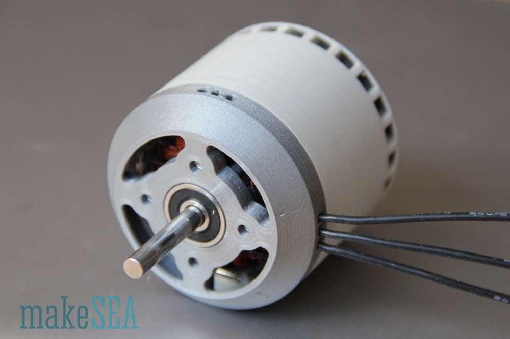
Here are the basic measurements and characteristics of the generator:
Of course the generator works as well with higher RPM (with storm-winds), but so far the generator behavior at low wind speeds is more important.
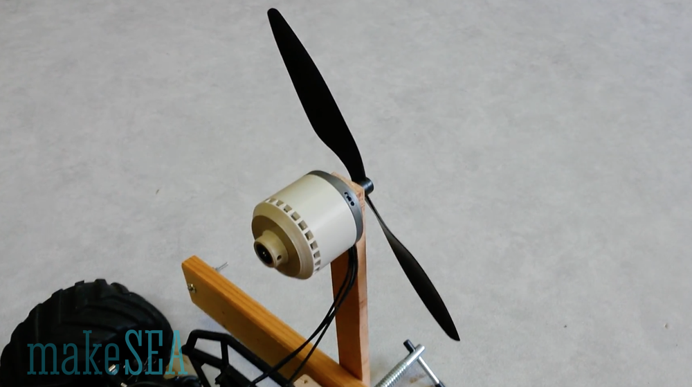
The Kv figure doesn’t tell much about the real efficiency as a generator, when it’s charging a big capacitor (or a battery). Because I didn’t have an appropriate / measurable load ready for this test, I was using this generator as a motor. Load means, that there is some power produced - Voltage and Current in the copper wires needs to be different than zero. Motor and generator are reciprocal anyway. As load I used my well known propeller with 10 inch diameter and 4.5 inch pitch. It wasn’t surprising, that the motor doesn’t rotate very fast, if the 6 cell NiMH battery with 7.2V was used. In fact the motor didn’t even start rotating on it’s own, but with a gentle kick by hand it worked. The problem with getting started isn’t the motor, but the combination with the ESC and the battery. Compared with the regular motor, the system behaves as if the RC car was driven with only a single and almost empty cell NiMH. So I have done these tests also with another ESC from a RC car, which runs at 6S LiPo (roughly 24V). With the higher voltage (and the other ESC) the motor could start spinning without issues.
Propeller constante: 1.63E-09 [N*m/RPM^2] … the number was calculated from previous measurements with the brushless motor at much higher RPM. This number is now very useful to calculate the power at low rotation speeds, because it wasn’t possible to measure the torque (the resolution of my scale is too bad).
There is a nice online calculator on which can compute the efficiency based on a few fundamental motor constants (Voltage, Current, I0, Kv, Rm).
The similarity of the calculated efficiency and the measured efficiency with 6S LiPo is amazing. It means that the ESC doesn't have much losses (no wonder - it’s designed for 100A continuous load). The result for the lower voltage isn’t reliable: the measurements of the current are at the limit of the resolution of my instruments, and if the ESC had losses of only 1W, it would distort the results a lot.
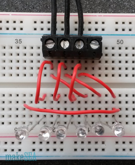
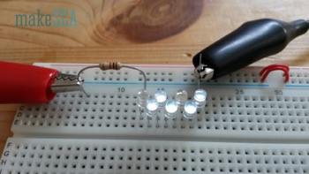
Finally I’ve done a last measurement with 6 red LEDs as a simple load. A red LED lights up very bright already at 1.8V. With the 3 phase generator it is possible to make a knight-rider flashing light.
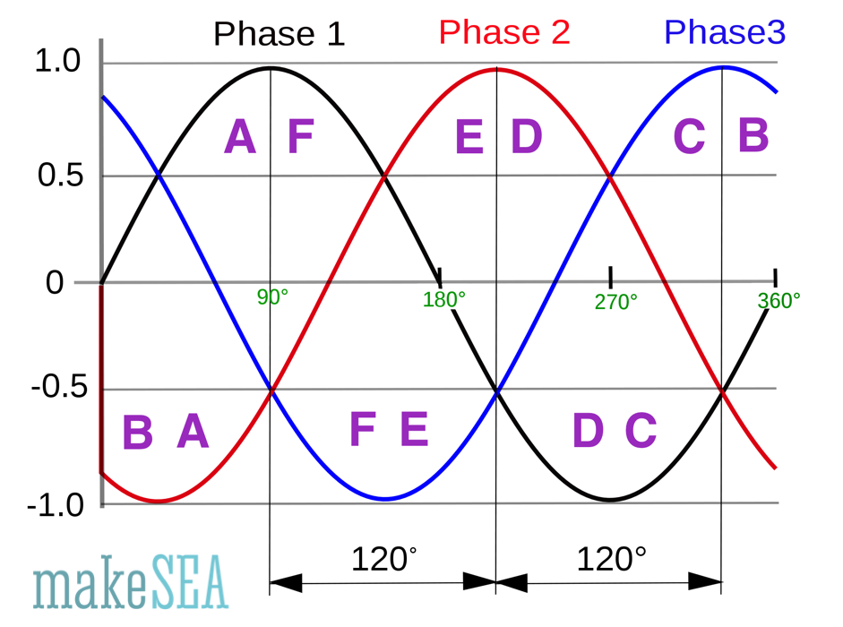
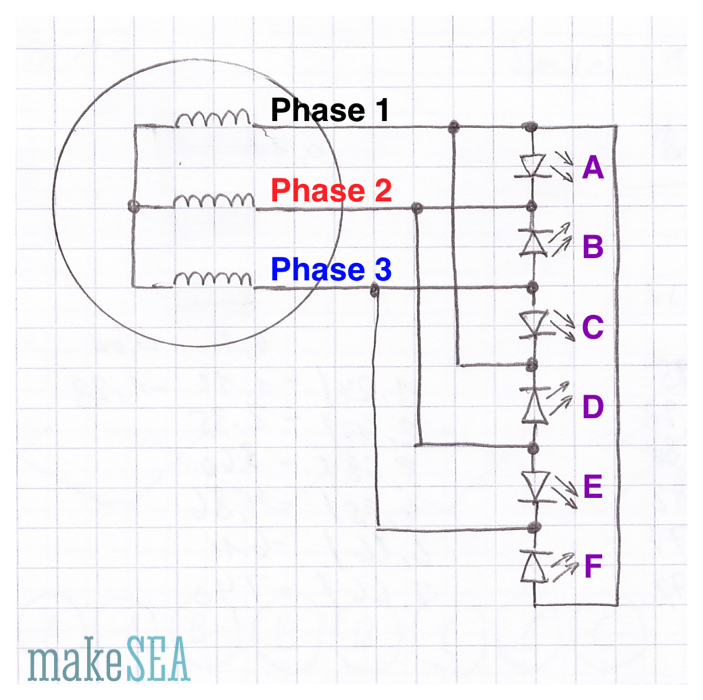 See Wikipedia for more info about the 3 phase signal. Our generator produces such a signal, whereas frequency and amplitude depend on the rotation speed. In the circuit LED A lights up, if the voltage of Phase 1 (black) is 1.8V higher than the voltage of Phase 2 (red). LED B lights up, if Phase 3 (blue) is higher than Phase 2 (red), etc. That’s a fun circuit - the LEDs light up in sequence, whereas 2 or 3 LED are on at the same time (e.g. at 180° LEDs D, E, and F are lit and the rest is dark).

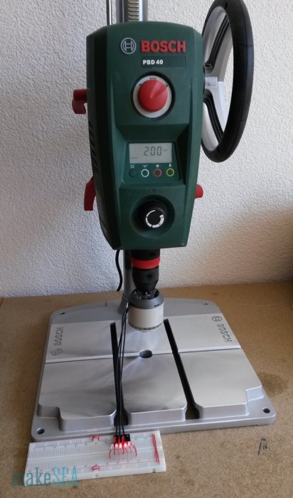
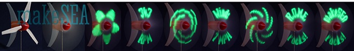
The LEDs light up already, if I manually turn the rotor with very little effort. Anyway I’ve fixed the generator in my drill-press rotating at only 200 RPM and took a photo while moving my camera across the LED-bar. With the camera exposure time, light during a period of several milliseconds is collected. The blurred image shows, how the individual LEDs light up in serial sequence due to the 120° shifted phases of the generator (if they would light up all at the same time, the LEDs would appear horizontally arranged). Hello Blinky! ...
 The LEDs in this circuit theoretically should be protected by a resistor. They would be damaged at higher voltages. I was luckily able to contain myself to crank up the RPM of the drill press. Blowing up an LED isn’t very spectacular - it gets hot and the light gets darker until if finally extinguishes. With some luck there is a little bit of smoke ...
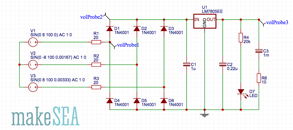
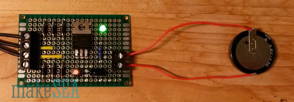
The generator is modeled with 3 AC voltage sources at 8 V amplitude and 100 Hz frequency. For the internal resistance of the generator, there are 3 resistors with 20 Ohm. Large capacitors need to be carefully charged - especially a specific voltage must not be exceeded. For this reason I’ve added a common 5 V regulator, which requires C1 and C2 at it’s in- and output. The LED indicates, if there is voltage at the output. I’ve used a bright green low-power LED with a large resistor (20 kOhm). Basically it’s not useful to have such a permanent consumer-LED in a low power application, and maybe I’ll remove that LED, when the whole thing is working. In reality I’ll have a 500 F capacitor to store the energy, but for the current tests I needed something smaller which quicker indicates, if it’s working: the “big” charged capacitor in this test-circuit has a capacity of only 1 mF (500’000 times less).
The circuit has some basic flaws: The voltage regulator can handle input voltage up to 40 V. With strong winds, the generator can produce much more, and the regulator will probably blow up. The regulator also doesn’t have a heat-sink for cooling - with only a small load, it should survive. If the big capacitor is completely empty, and there are stronger winds, the charging current could be very high for a longer time. The relative high resistance of the generator coils will luckily limit the current (at 0.5A load the generator heats up with a rate of 30W). More power can’t be expected with small propeller blades. In this case it’s good to have inferior efficiency at the generator (which is well cooled), so it won’t burn anything else.
The simulation shows the voltage at 3 selected points (probes 1..3). First directly one of the generator wires (blue), then after the rectifier (red), and finally the output (yellow).
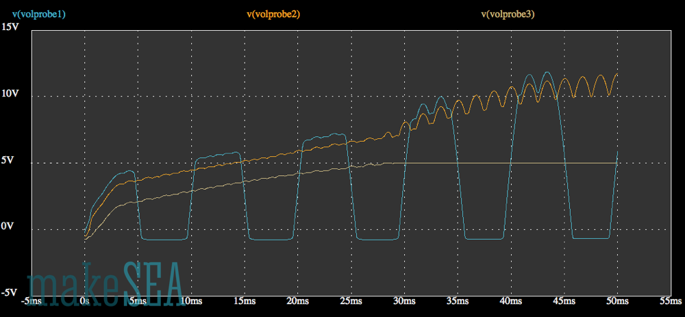
Initially all capacitors are not charged (0V). The output voltage (yellow) increases up to 5 V, and then it remains stable. While it’s increasing, the big capacitor is charged. During that time the voltage at the generator wires (blue) and the rectified voltage (red) have a small constant offset from the output voltage. This offset is roughly 1.5V and is caused by the voltage regulator, which draws as much as possible current from the generator and the generated voltage is lost inside the generator. As soon as the big capacitor is fully charged, the load decreases, and the generator voltage can further increase. It increases depending on the actual rotation speed, and can be calculated based on Kv.
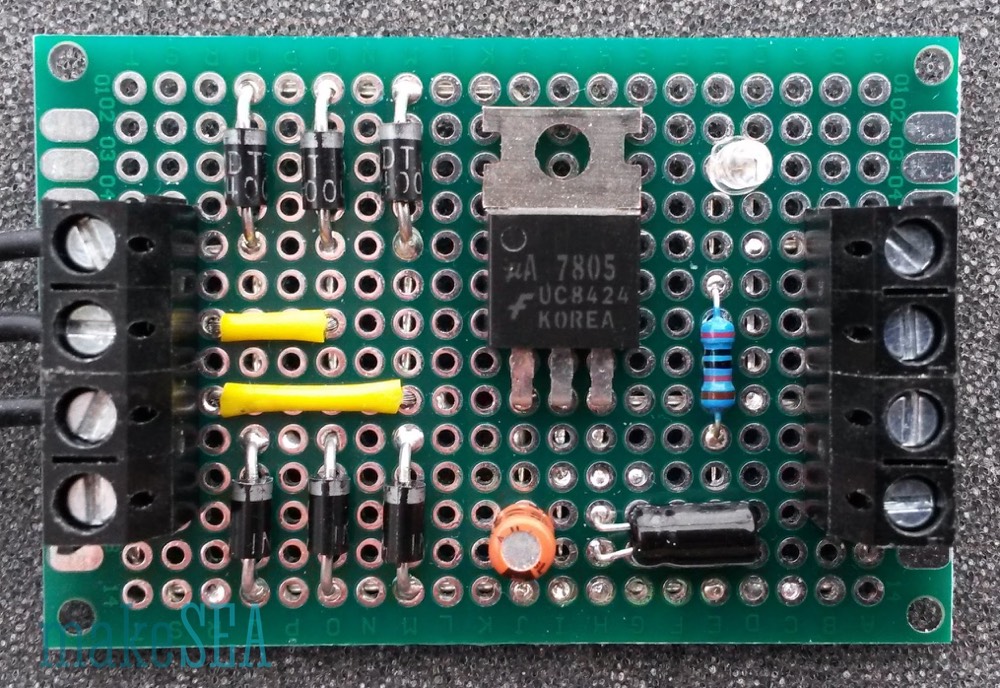
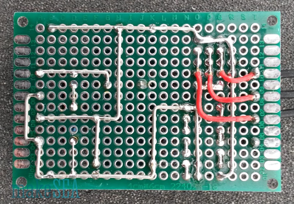
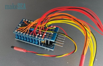
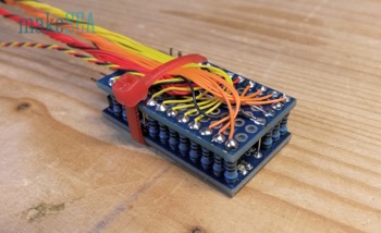
 There is not much magic about soldering this circuit on a PCB. The images tell how it’s done. The components are all standard, and it would also work with different diodes or capacitors. The only thing I realized at the end: the fin of the voltage regulator needs to be isolated from the pads behind it, because I placed the rectified signal on the backside right beneath the fin (which is grounded). There would have been enough space for the rectified signal 2 grid units further right. No tragedy … time for testing:
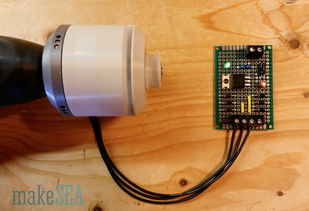
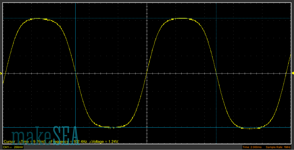
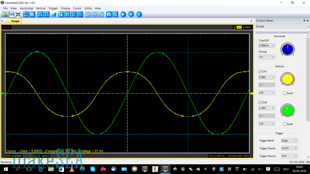
For the initial test I didn’t connect the big capacitor. Just the basic rectifier, with its LED and some smaller caps on-board. Hence the charging-process is very quick. I quickly pushed the drill throttle, but on the scope it’s still visible, that it needs some time until the drill rotates at final speed.
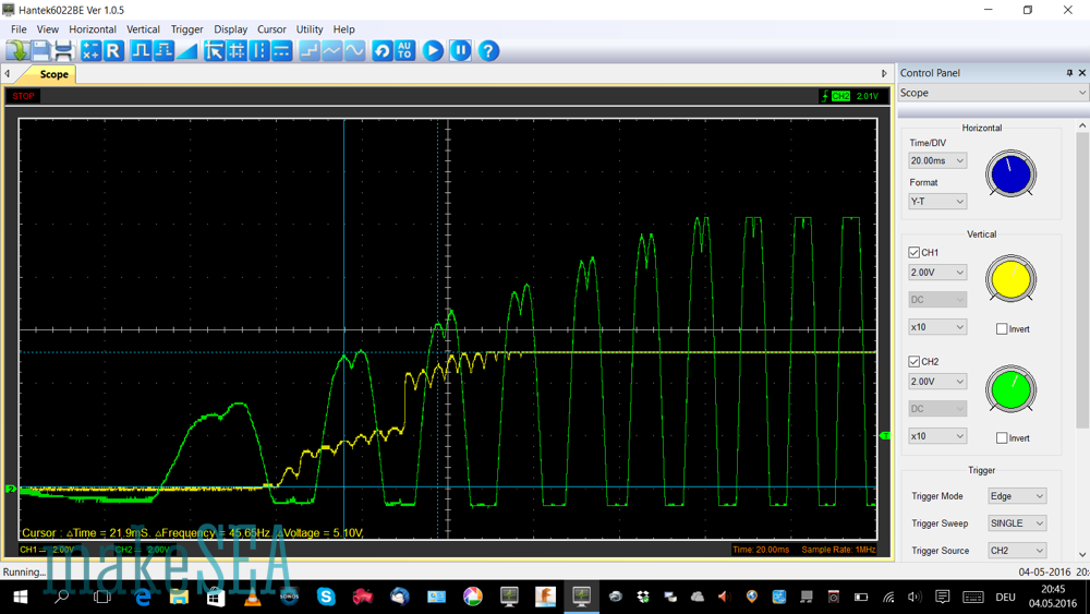
The green curve is one wire directly at the generator, the yellow curve is the output signal. The rectified signal is missing (my scope has only 2 channels). Differently to the simulation, the generator amplitude and frequency is ramping up until it has full speed. This makes it a bit difficult to interpret the charging process of the capacitor. Anyway, it’s visible that the voltage regulator does its job, and limits the output at 5V.
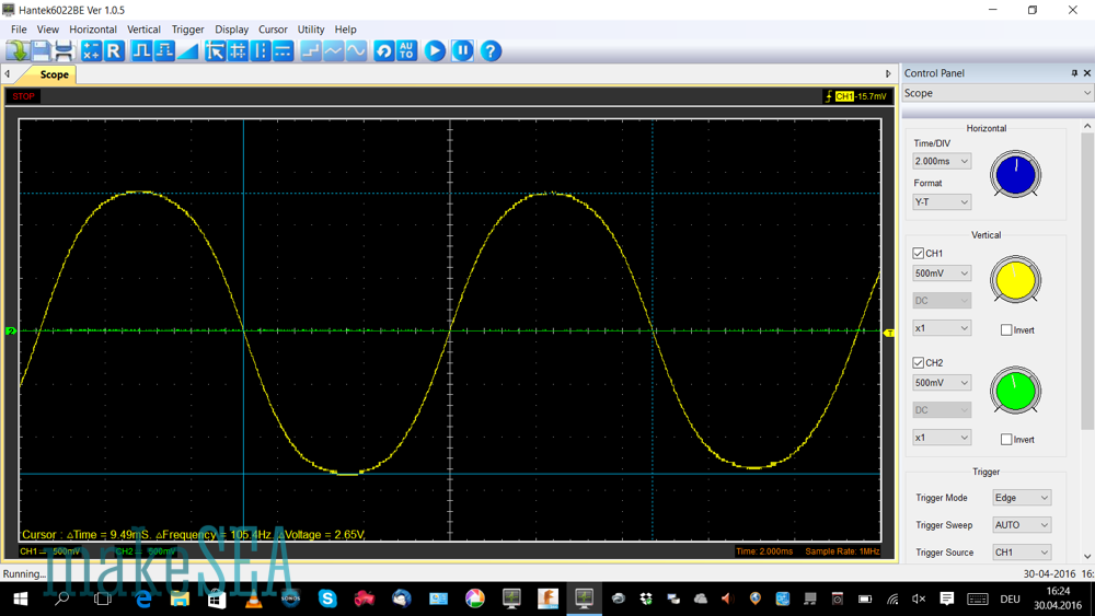
Then I’ve connected a 4F capacitor as a load to be charged. Charging takes much longer.
The ramp-up of the drill speed is no longer relevant, however it takes MUCH more time to observe the charging process. I’ve done two measurements: first snapshot when the capacitor isn’t charged, and the second snapshot 2 Minutes later, when the capacitor is full.
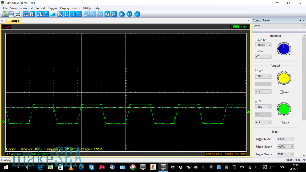
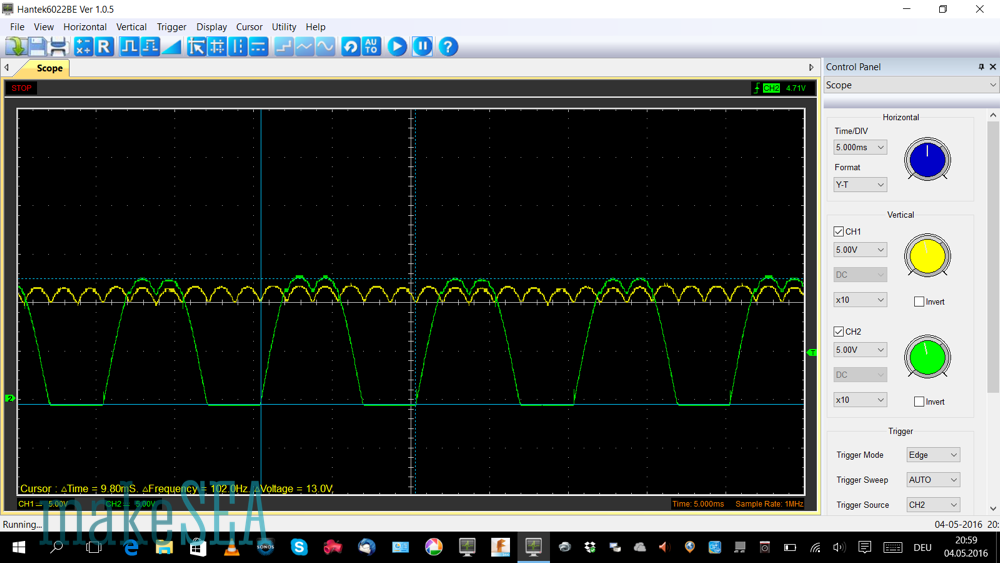
The green line shows again the voltage at the generator, but the yellow curve is now showing the rectified signal. The output stays stable at 5V anyway and isn’t displayed. The measurements remind on the simulation result: while the capacitor is being charged, the voltage is not much above the output signal (which is around 3-4 volts at that time). Later when the capacitor is fully charged the rectified voltage increases up to 12V.
The modified circuit doesn’t look much different than the prior version, but it’s much more efficient.
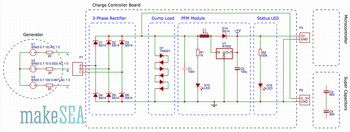
The 3-Phase rectifier converts the AC signal into a DC signal. It uses Schottky diodes, which have a lower voltage drop than regular diodes. With the DC signal the super caps are charged.
A simple dump-load made of 7 regular diodes limits the loading voltage to roughly 5V (the voltage drop of a single diode is roughly 0.7V). 6V => 275mA, 5V => 20mA, 4V => 0.8mA, 3V => 0.05mA.
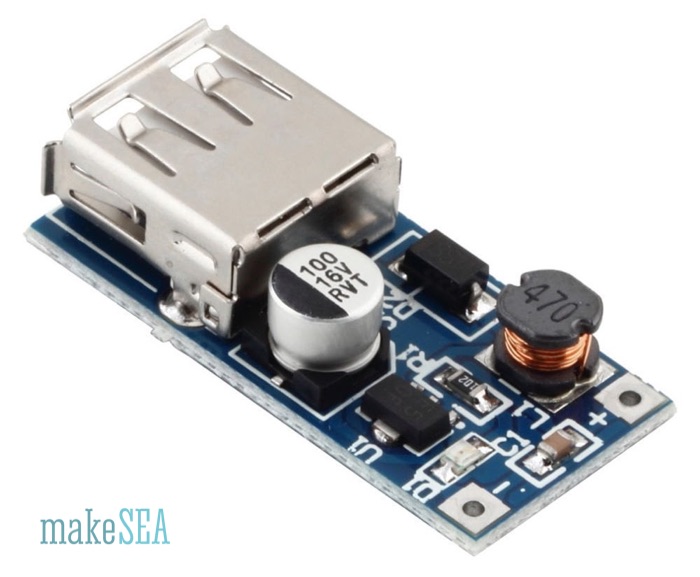
The PFM-Module gets the power from the supercaps and converts the voltage to 5V. A low-power LED with a 20kOhm resistor is indicating the output power (it “eats” only 0.1mA).
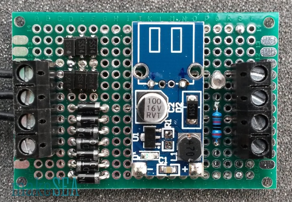
 I’ve used the SMD-version of the Schottky diodes (SS14), because I had some spare parts. The SS14 is also available with a regular shape, easier to solder. I’ve also de-soldered the resistor R1 from the PFM module, because with only 1kOhm the LED on board consumers a relevant amount of current. I’ve also removed the USB-connector - it’s not needed, and I wanted to have access to the +5V output pad.
This charger works amazingly well. Without connecting the supercaps the output LED is already lit, when the generator is rotated only ¼ turn by fast manual move. It’s charging the supercaps below 200RPM, and the PFM module works already at 0.2V input voltage.
Theoretically a lithium battery could also be used instead of the supercaps. But the problem with the battery is the working range between 3.3V and 4.2V. The circuit would need to be changed: the battery needs to be charged by the PFM module.
The circuit scheme has 3 main blocks:
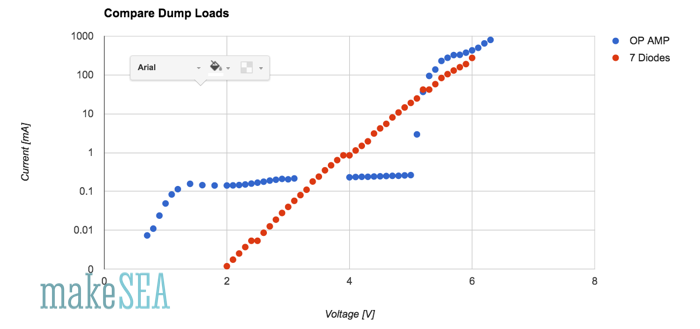
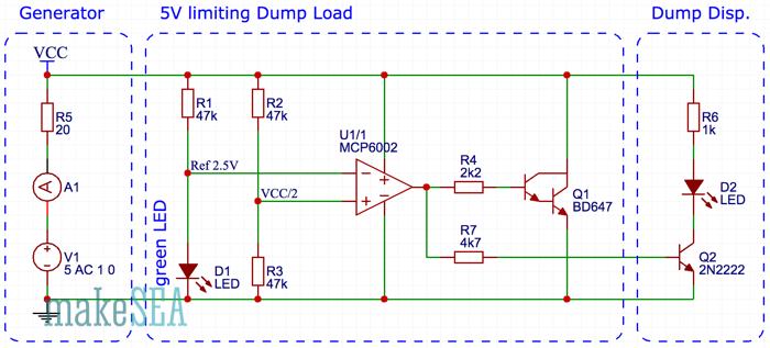
Below 5V the circuit with the circuit draws roughly a constant current of 0.25mA (2 x 0.05mA by the voltage divider and the voltage reference, 0.15mA by the Op Amp). At 5V there is a steep increase (depending on the resistance of the cables from my power supply). Below 3.5V the 7-diodes have a better performance: At 2V the Op Amp wastes 100 times more current than the diodes - current, which could be used to charge the supercap. However the absolute value of the current needs to be compared with the current needed finally by the microcontroller. An Arduino Pro Mini with some LEDs connected will need at minimum 5mA, so it’s not relevant if 0.25mA are lost.
As next the circuit would need to be properly soldered on a PCB, but I’ll wait until the rest of the wind turbine is finished (the circuit with the diodes as dump load is good enough for testing).
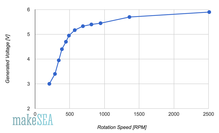
Up to 500 RPM the voltage increases approx. linearly until 5V. At higher speeds the voltage is almost flat. That’s the expected effect caused by the passive dump load (7 diodes). Up until 5V the dump-load is not dumping much current - the voltage can increase corresponding to Kv. At higher rotation speeds the diodes are “eating” more and more current. The superfluous energy is then wasted as heat in the diodes and the generator copper wires. If there was no dump-load attached with Kv=80 RPM/V the generated voltage at 2’500 RPM would be at 31V.
Interesting to note: at 200 RPM the generated voltage is around 3V.
The next measurement is the current with the rectified signal short-circuited:
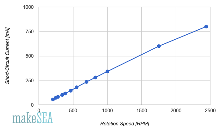
The curve is almost perfectly linear. As expected. The resistance of the generator copper wires is the reason. The induced voltage increases linearly with the rotation speed (U = RPM/Kv), and since the resistance is constant, also the current increases linearly (I = U/R). Assuming 31V at 2500RPM with 800mA current, the generator has a power loss of 25W - all heating up the copper wire. In-deed after only 30 seconds on the drill-press, the stator is remarkably warm.
Interesting to note: at 200 RPM the short-circuit current is over 50mA.
Arduino Pro Mini 3.3V, 8MHz:
LEDs:
Hall Switch (3141):
⇒ high power consumption, use additional transistor to turn it on or off
⇒ evaluate magnetic reed-switch?
For demonstration I’ve connected all with an Arduino Pro Mini. In the video I’m turning the generator with my hand (very slowly). The green LED on the charge controller lights up, and the red LED on the Arduino is flashing randomly and bright while it’s booting. Once booting is finished, my program starts running. The program on the Arduino does a short double-flash with the red LED every two seconds. In-between the arduino is sleeping.


Of course this display is difficult to read during the day with glaring sun-light, or if there is no wind. Anyway it’s a demonstration of the future - the Internet of Things is coming: there will be a web-server inside the propeller-hub, the energy stored in the battery will be used for communication. Users will be able to browse this Wind Turbine with their Smartphone. They will obtain weather information, and they will be able to post their tweets onto the propeller, even if there is no wind … ;-)
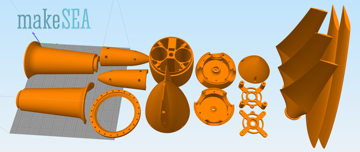
With this project I wanted to create something, which is crafted mainly by using the new element: 3d-printing filament! Components, which are not 3d-printable should be minimized, and they should be very basic: copper-wire, magnets, screws. Intelligence is inserted into this system by using an Arduino. All the project details are open-source, published on makeSEA.com. People with a 3d-printer, a solder iron, and an Arduino in their workshop should be able to “download” this Wind Turbine, or parts of it.
I’d like to sensibilize people, that the world of today has a heart, and humans are responsible for it. A smart-phone is not smart - the inventor of this phone is smart! We all are humans, and we should consider our potential. The Wind Turbine demonstrates the use of ecological energy. It’s an autonomously working gadget. Eco friendliness, luxury, and fun are partners. The reason how the Wind Turbine works is not just magic - it’s simple physics and not religion. If somebody walks through this project, he (or she) will have a different view at the “modern” gadgets. I’d like to encourage people to not just stack huge and complex building blocks on top of an unknown base. It could be very dangerous, the system behaves unpredictably and operates very inefficient. Look behind the scenes and have fun!
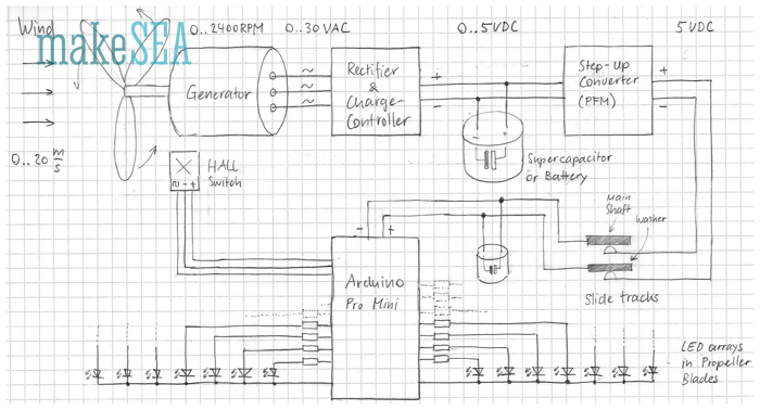
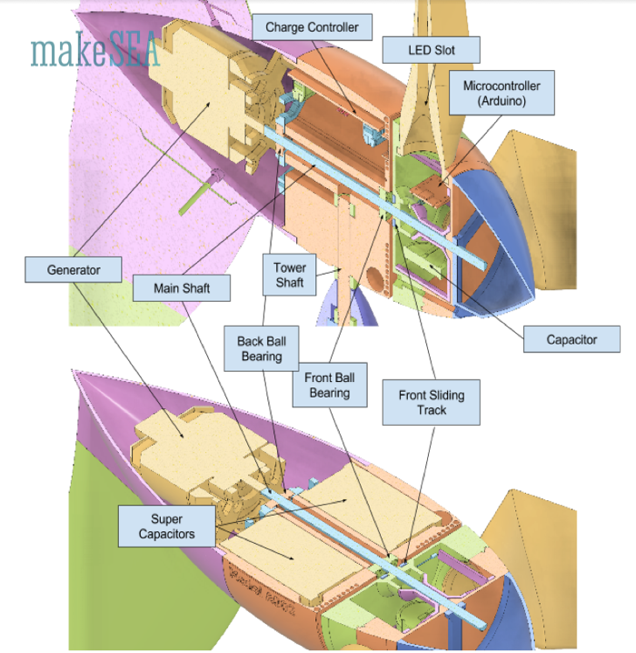
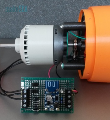
The wind turns the propeller and the direct driven generator. The generator produces 3-phase AC voltage. The AC is then rectified, and limited to 5V. The overvoltage is “burned” (dump-load) in order to prevent overloading the super capacitors. A step-up converter creates constant 5V even if capacitors are not yet fully charged. In the propeller hub there is an Arduino, which controls 7 LEDs in each blade. A Hall-Sensor triggers a signal with each full revolution, and the Arduino uses this signal in order to turn on or off LEDs, and “paint” a stable pattern with the LEDs.
Rectifier, Charge-Controller and Step-Up-Converter are all on a single PCB. For simplicity I’ll often name this PCB only Charge-Controller.
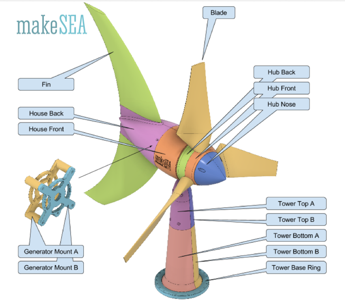
These are the main 3d-printable (exterior) components for the Wind Turbine. They are held together with 17 screws. Most parts can be printed without support. Support is needed for the tower parts, house front, hub back. Printing orientation: largest flat surface oriented towards print-bed.
Descriptions about the generator and the charge controller can be found in the other documents about the development of these internal components (“Wind Turbine internal Components”). Maybe I’ll merge these files later ...
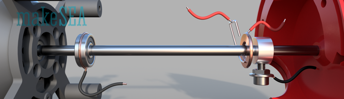
If one long shaft is used connecting generator and propeller hub directly, the back ball bearing in the house and the front ball bearing in the generator are not needed.
Sliding Tracks:
Sliding tracks minus pole: (ab-) using a ball bearing (next to generator):
 Sliding tracks plus pole:
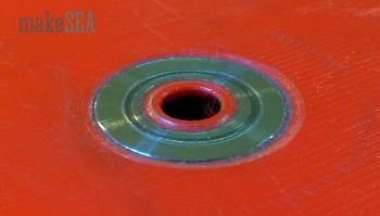
 Gluing a 8x16mm washer with epoxy4:
4. The washer needs to be level or flush with the housing so that when the turbine turns it will not “wiggle” -D.Hartley

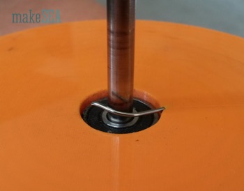 Connections inside the propeller hub. Plus-pole from washer, minus-pole from shaft collar:
 LED arrays:
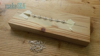
 Seven 3mm LEDs with 14mm spacing. Before soldering the LEDs, check if they actually all work: connect 7 white LEDs in series with 1kOhm at 18V, and they should all evenly bright light up.5
5. If you do not have a good wire stripper to strip thin wires, then I would recommend using a lighter to light the end of the wire and just pull the plastic off. It works great, but be careful! To avoid problems, I would recommend soldering each negative lead of the LED together with 14 mm of spacing for each blade (3 sets of 7 LEDs). Then I would start from the top of the LEDs and solder the thin wire to the positive lead of the LED and weave the wire around the rest of the LEDs (shown above). The wire needs to extend from the last LED at least the length of the LEDs soldered together, but it can be longer, you just might have to cut it later. Once all seven of one strand of LEDs are soldered with wires then shrink tube at least half the length of the wire extending from the last LED. This will make it easier to manage the wires in the housing. Do this again for the other two strands of LEDs. Once all of the LEDs are wired and shrink tubed, then you are good to move on. -D. Hartley
Arduino: We are using the 8MhZ, 3.3V version:
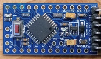 De-solder the 1k resistor from the red power-indicator LED. It’s useless: needs 80% of the energy, in case the Arduino is set to sleep (if there is no wind).
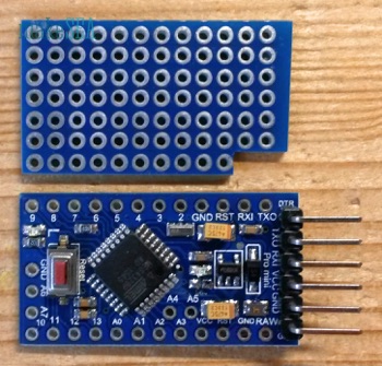
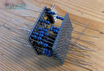 Using a PCB with 7 x 12 pads. Connecting EACH analog and digital pin with a resistor (180Ohm with white LEDs).6
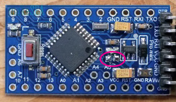
When using A6 as input for the Hall-Switch, a pull-up resistor 4k7 is needed.7
6. For this step, you will need 22 180 Ohm resistors. You will also need to connect the PCB to ground terminals on the Arduino using leftover parts from cutting the resistors. In total, 3 ground terminals will be wired to the PCB, and 22 Resistors will be connected to terminals TX0, Rx1, 2-13, and A0-A7. 20 of these terminals will be wired to LEDs. The ones that are not wired to LEDs are A6 and A7. A6 is wired to the Hall-Switch, and A7 is not wired to anything. -D. Hartley
7. The 4k7 resistor is soldered to VCC and A6. -D. Hartley
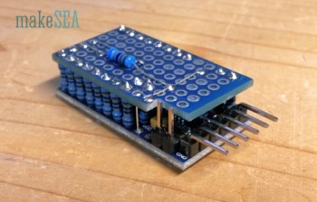
 Arduino Pro Mini has only 20 outputs. With 7 LEDs and 3 propeller blades, 1 output is missing. I’m “cheating”: leave one of the inner LEDs unconnected. Use pins 0-6 for Blade A, pins 7-13 for Blade B, A0-A5 for Blade C (1 inner LED unconnected), and A6 or A78 for the Hall Switch. Basically all LEDs could be wired randomly - make soldering work simple. The final connection scheme can easily be adjusted in the software.9 Instead of the Hall Switch, a Read-Switch maybe also works.
8. A6 (only) for the Hall Switch.
9. I would not recommend doing it this way as it will take time to go through each wiring of the LED and line it up with the code. Also using different colored wires helps a ton. -D. Hartley
Magnet and Hall-Switch:

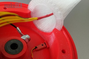 The magnet in this image is glued into the front house with hot glue, the published design has a proper spacing, where a 3 x 10 x 30 mm magnet can be snapped in. There is also a proper space in the back propeller hub for the Hall-Switch. Carefully test the system before firmly gluing all components: the Hall-Switch works only with one orientation of the magnetic field (maybe you need to flip the magnet or the switch).
More on the Installation of the Capacitors and How they Work:
A capacitor (or also a battery) can be compared with a reservoir. The water pressure corresponds to the voltage. Water flow (gallons/sec) corresponds to the current. A water pump makes the water flowing through the pipes - pressure at the output is higher that at the input.
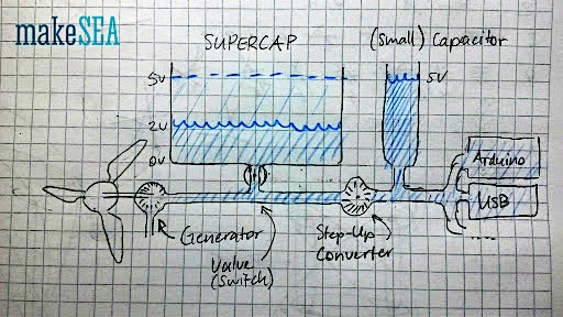 The windpowerWriter has a big reservoir (supercaps) and a small reservoir (little capacitor in the hub). The voltage from the generator (1.pump) depends on the wind speed. The step-up-converter (2.pump) generates always 5V as long as its input voltage is higher than 1V. In my demo-turbine I've added this switch at the bottom of the house (valve), which allows to disconnect the supercaps. If the supercaps are connected (valve open), the generator charges the supercaps AND supplies the step-up-converter together. If the supercaps are disconnected (valve closed), the generator only supplies the step-up-converter, and the charging state of the supercaps remains constant. Usually supercaps are connected (valve open). I.e. the step-up-converter can output 5V even if there is no wind - it discharges the supercaps.
For the life-demo I've added the switch, because the arduino would always run, and people couldn't recognize, that the generator is actually working when there is wind. And if the supercaps are completely empty it takes a wile, until they are charged at the minimum level required for the step-up-converter.
 You should connect the caps at the input of the step-up-converter (like illustrated in the google-drawing below). The washer is connected at the output, and the Arduino would only work in a very small range, if the caps are fully charged (4.5V to 5.0V). Interrupting the plus-wire is OK. Make sure, the capacitors are in series, and with proper polarity. Charging 500F-Capacitors takes some time. I had the fan blowing at the turbine for roughly 30 minutes, until the capacitors were charged to approximately 1V. Below that voltage, the step-up-converter wont work (and the Arduino isn't powered). The behaviour of charging capacitors is similar like filling a pool with water: with a constant current, the voltage increases continuously.
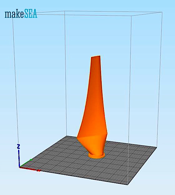 We used an Ultimaker2 Extended at .15mm layer height and 30% infill, using translucent PLA filament. The Pro Series PLA avaialable from MatterHackers comes out georgous! On a shorter printer, you may need ot modify the original blade to be shorter with the supplied master file, or to print in interlocking pieces. You can also print on its side with support. Our other Propeller project does print on it's side, along the trailing edge with support, and works great. Don't forget to register your alterations with makesea and link back to the original design!
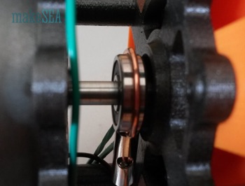
The drive shaft is supported by bearings that are nested in the sheild and hub.
XXX . V0 Improving wind turbine power conversion in variable speed wind turbines

The proposed T-type Grid Side Converter (GSC) DFIG converter scheme in the research paper is much easier to achieve with less switching circuitry when compared to the conventional 3-level multilevel converters
The proposed T-type Grid Side Converter (GSC) DFIG converter scheme in the research paper is much easier to achieve with less switching circuitry when compared to the conventional 3-level multilevel converters. Also, this scheme avoids the use of an external traditional expensive control strategy in achieving DFIG wind farm stability during grid disturbance.
The proposed converter topology for DFIG wind generators creates room for a sophisticated and robust converter controller implementation that would protect the fragile, vulnerable VSWT DFIG converters during grid fault scenarios.
Consequently, it would enable modern wind farms taking advantage of DFIG to remain grid connected - based on the grid codes or requirements to supply power to utilities during occurrences of “transients” - instead of having to disconnect from the grid. Also, instead of phasing out earlier wind turbines using the fixed speed technology, wind farms in the future could be composed of both fixed and variable speed wind turbines. This is because the variable speed wind turbines could help stabilise the fixed speed wind turbines and the entire wind farm during grid disturbances, at a lower cost, and without requiring expensive external reactive power compensators.
Amongst the various renewable energy sources, the use of wind energy is very common, considering the technological advancement of wind turbines and power electronics applications.
The common wind turbines either use Fixed Speed Wind Turbines (FSWT), made of the Squirrel Cage Induction Generator (SCIG) technology; or the Variable Speed Wind Turbine (VSWT), made of the Doubly Fed Induction Generator (DFIG)/Permanent Magnetic Synchronous Generator (PMSG).
The response of wind generators to grid disturbances is an important issue nowadays due to increased wind on the grid. Therefore, it is important that utilities and grid companies study the effects of various voltage sags on the corresponding wind turbine responses. Grid codes or requirements were formulated with the effective operation of grid-connected wind farms in mind. Such emerging grid codes demand that wind farms should have a good performance with respect to voltage control capability, and robust behaviour against frequency and voltage variations under fault condition.
The SCIG is used in general for FSWT generators due to its superior characteristics (i.e. brushless and rugged construction; low cost; maintenance free; and operational simplicity). However, it requires large reactive power to recover the air gap flux when a short circuit fault occurs in the power system. Therefore, reactive power compensation from power network or other devices is needed for a FSWT wind farm. The installation of compensation units in FSWT farms to overcome voltage sag during a grid fault (like static synchronous compensators (STATCOM); superconducting magnetic energy storage (SMES); and energy capacitor system (ECS) increases the system overall cost.
In general, the amount of the necessary dynamic reactive power compensation depends on the type of wind turbine generator system (WTGS), and is influenced by the relevant electrical and mechanical parameters of that system.
The doubly fed induction generator (DFIG) has very attractive characteristic as a wind generator because the power processed by the converter is only a fraction of the total power rating of the DFIG. This is typically 20%-30%, and therefore its size, cost, and losses are much smaller compared to a full size power converter used in other types of variable speed wind generators.
DFIG can operate at a wide range of speeds (depending on the wind speed or other specific operation requirements). Thus, it allows better capture of wind energy. The dynamic slip control and pitch control are the other salient features which help to augment the system stability. In addition, DFIG has better system stability during short-circuit faults in comparison with IG, because of its capability of independent control of active and reactive power output. This superior dynamic performance of the DFIG results from the frequency converter, which typically operates with sampling and switching frequencies of above 2 kHz. Therefore, it is paramount to use a VSWT system like a DFIG to stabilise a FSWT (IG) in a wind farm, because the DFIG system can also control reactive power in a similar manner to a STATCOM, SMES, or ECS, and thus the reactive power compensation can be implemented at a lower cost.
The results show improved performance of the DFIG wind generator during transient conditions considering the proposed scheme, thus saving the cost of traditional external expensive circuitry and more switching Insulated Gate Bipolar Transistors (IGBTs) used in the conventional 3-level multilevel converters for the DFIG Fault Ride Through (FRT) capability.
In addition, the simple extension of the conventional 2-level Grid Side Converter (GSC) of the DFIG wind generator to a 3-level topology by the bidirectional middle switch with two Insulated gate Bipolar Transistors (IGBTs) in common emitter connections, leads to low switching losses; low forward voltage drop; and only one more isolated gate drive supply per phase leg; when compared with the conventional 2-level converter.

Wind power first appeared in Europe during the Middle Ages. The first historical records of their use in England date to the 11th or 12th centuries and there are reports of German crusaders taking their windmill-making skills to Syria around 1190.[6] By the 14th century, Dutch windmills were in use to drain areas of the Rhine delta. Advanced wind turbines were described by Croatian inventor Fausto Veranzio. In his book Machinae Novae (1595) he described vertical axis wind turbines with curved or V-shaped blades.
The first electricity-generating wind turbine was a battery charging machine installed in July 1887 by Scottish academic James Blyth to light his holiday home in Marykirk, Scotland.[7] Some months later American inventor Charles F. Brush was able to build the first automatically operated wind turbine after consulting local University professors and colleagues Jacob S. Gibbs and Brinsley Coleberd and successfully getting the blueprints peer-reviewed for electricity production in Cleveland, Ohio.Although Blyth's turbine was considered uneconomical in the United Kingdom electricity generation by wind turbines was more cost effective in countries with widely scattered populations.

The first automatically operated wind turbine, built in Cleveland in 1887 by Charles F. Brush. It was 60 feet (18 m) tall, weighed 4 tons (3.6 metric tonnes) and powered a 12 kW generator.[8]
By the 1930s, wind generators for electricity were common on farms, mostly in the United States where distribution systems had not yet been installed. In this period, high-tensile steel was cheap, and the generators were placed atop prefabricated open steel lattice towers.
A forerunner of modern horizontal-axis wind generators was in service at Yalta, USSR in 1931. This was a 100 kW generator on a 30-meter (98 ft) tower, connected to the local 6.3 kV distribution system. It was reported to have an annual capacity factor of 32 percent, not much different from current wind machines.[10]
In the autumn of 1941, the first megawatt-class wind turbine was synchronized to a utility grid in Vermont. The Smith-Putnam wind turbine only ran for 1,100 hours before suffering a critical failure. The unit was not repaired, because of shortage of materials during the war.
The first utility grid-connected wind turbine to operate in the UK was built by John Brown & Company in 1951 in the Orkney Islands.[7][11]
Despite these diverse developments, developments in fossil fuel systems almost entirely eliminated any wind turbine systems larger than supermicro size. In the early 1970s, however, anti-nuclear protests in Denmark spurred artisan mechanics to develop microturbines of 22 kW. Organizing owners into associations and co-operatives lead to the lobbying of the government and utilities and provided incentives for larger turbines throughout the 1980s and later. Local activists in Germany, nascent turbine manufacturers in Spain, and large investors in the United States in the early 1990s then lobbied for policies that stimulated the industry in those countries. Later companies formed in India and China. As of 2012, Danish company Vestas is the world's biggest wind-turbine manufacturer.
Resources
Wind power
A quantitative measure of wind energy available at any location is called the Wind Power Density (WPD). It is a calculation of the mean annual power available per square meter of swept area of a turbine, and is tabulated for different heights above ground. Calculation of wind power density includes the effect of wind velocity and air density. Color-coded maps are prepared for a particular area described, for example, as "Mean Annual Power Density at 50 Metres". In the United States, the results of the above calculation are included in an index developed by the National Renewable Energy Laboratory and referred to as "NREL CLASS". The larger the WPD, the higher it is rated by class. Classes range from Class 1 (200 watts per square meter or less at 50 m altitude) to Class 7 (800 to 2000 watts per square m). Commercial wind farms generally are sited in Class 3 or higher areas, although isolated points in an otherwise Class 1 area may be practical to exploit.
Wind turbines are classified by the wind speed they are designed for, from class I to class IV, with A or B referring to the turbulence.
| Class | Avg Wind Speed (m/s) | Turbulence |
|---|---|---|
| IA | 10 | 18% |
| IB | 10 | 16% |
| IIA | 8.5 | 18% |
| IIB | 8.5 | 16% |
| IIIA | 7.5 | 18% |
| IIIB | 7.5 | 16% |
| IVA | 6 | 18% |
| IVB | 6 | 16% |
Efficiency
Conservation of mass requires that the amount of air entering and exiting a turbine must be equal. Accordingly, Betz's law gives the maximal achievable extraction of wind power by a wind turbine as 16/27 (59.3%) of the total kinetic energy of the air flowing through the turbine.[14]The maximum theoretical power output of a wind machine is thus 16/27 times the kinetic energy of the air passing through the effective disk area of the machine. If the effective area of the disk is A, and the wind velocity v, the maximum theoretical power output P is:
- ,

As wind is free (no fuel cost), wind-to-rotor efficiency (including rotor blade friction and drag) is one of many aspects impacting the final price of wind power.[15] Further inefficiencies, such as gearbox losses, generator and converter losses, reduce the power delivered by a wind turbine. To protect components from undue wear, extracted power is held constant above the rated operating speed as theoretical power increases at the cube of wind speed, further reducing theoretical efficiency. In 2001, commercial utility-connected turbines deliver 75% to 80% of the Betz limit of power extractable from the wind, at rated operating speed.
Efficiency can decrease slightly over time due to wear. Analysis of 3128 wind turbines older than 10 years in Denmark showed that half of the turbines had no decrease, while the other half saw a production decrease of 1.2% per year.[18] Vertical turbine designs have much lower efficiency than standard horizontal designs.
Types

The three primary types: VAWT Savonius, HAWT towered; VAWT Darrieus as they appear in operation
Horizontal axis

Any solid object produces a wake behind it, leading to fatigue failures, so the turbine is usually positioned upwind of its supporting tower. Downwind machines have been built, because they don't need an additional mechanism for keeping them in line with the wind. In high winds, the blades can also be allowed to bend which reduces their swept area and thus their wind resistance. In upwind designs, turbine blades must be made stiff to prevent the blades from being pushed into the tower by high winds. Additionally, the blades are placed a considerable distance in front of the tower and are sometimes tilted forward into the wind a small amount.
Turbines used in wind farms for commercial production of electric power are usually three-bladed. These have low torque ripple, which contributes to good reliability. The blades are usually colored white for daytime visibility by aircraft and range in length from 20 to 80 meters (66 to 262 ft). The size and height of turbines increase year by year. Offshore wind turbines are built up to 8MW today and have a blade length up to 80m. Usual tubular steel towers of multi megawatt turbines have a height of 70 m to 120 m and in extremes up to 160 m.
The blades rotate at 10 to 22 revolutions per minute. At 22 rotations per minute the tip speed exceeds 90 meters per second (300 ft/s). Higher tip speeds means more noise and blade erosion. A gear box is commonly used for stepping up the speed of the generator, although designs may also use direct drive of an annular generator. Some models operate at constant speed, but more energy can be collected by variable-speed turbines which use a solid-state power converter to interface to the transmission system. All turbines are equipped with protective features to avoid damage at high wind speeds, by feathering the blades into the wind which ceases their rotation, supplemented by brakes.
Vertical-axis wind turbines (or VAWTs) have the main rotor shaft arranged vertically. One advantage of this arrangement is that the turbine does not need to be pointed into the wind to be effective, which is an advantage on a site where the wind direction is highly variable. It is also an advantage when the turbine is integrated into a building because it is inherently less steerable. Also, the generator and gearbox can be placed near the ground, using a direct drive from the rotor assembly to the ground-based gearbox, improving accessibility for maintenance. However, these designs produce much less energy averaged over time, which is a major drawback.[23][27]
The key disadvantages include the relatively low rotational speed with the consequential higher torque and hence higher cost of the drive train, the inherently lower power coefficient, the 360-degree rotation of the aerofoil within the wind flow during each cycle and hence the highly dynamic loading on the blade, the pulsating torque generated by some rotor designs on the drive train, and the difficulty of modelling the wind flow accurately and hence the challenges of analysing and designing the rotor prior to fabricating a prototype.[28]
When a turbine is mounted on a rooftop the building generally redirects wind over the roof and this can double the wind speed at the turbine. If the height of a rooftop mounted turbine tower is approximately 50% of the building height it is near the optimum for maximum wind energy and minimum wind turbulence. Wind speeds within the built environment are generally much lower than at exposed rural sites, noise may be a concern and an existing structure may not adequately resist the additional stress.
Subtypes of the vertical axis design include:
Design and construction
Wind turbine design
Wind turbines are designed, using a range of computer modelling techniques,[37] to exploit the wind energy that exists at a location. For example, Aerodynamic modeling is used to determine the optimum tower height, control systems, number of blades and blade shape.

Wind turbines convert wind energy to electricity for distribution. Conventional horizontal axis turbines can be divided into three components:
- The rotor component, which is approximately 20% of the wind turbine cost, includes the blades for converting wind energy to low speed rotational energy.
- The generator component, which is approximately 34% of the wind turbine cost, includes the electrical generator,[38][39] the control electronics, and most likely a gearbox (e.g. planetary gearbox),[40] adjustable-speed drive or continuously variable transmission[41] component for converting the low speed incoming rotation to high speed rotation suitable for generating electricity.
- The structural support component, which is approximately 15% of the wind turbine cost, includes the tower and rotor yaw mechanism.
Among all renewable energy systems wind turbines have the highest effective intensity of power-harvesting surface because turbine blades not only harvest wind power, but also concentrate it.
Unconventional designs
Unconventional wind turbines


Wind turbines which utilise the Magnus effect have been developed.
A ram air turbine (RAT) is a special kind of small turbine that is fitted to some aircraft. When deployed, the RAT is spun by the airstream going past the aircraft and can provide power for the most essential systems if there is a loss of all on-board electrical power, as in the case of the "Gimli Glider".
The two-bladed SCD 6MW offshore turbine designed by aerodyn Energiesysteme and built by MingYang Wind Power has a helideck for helicopters on top of its nacelle. The prototype was erected in 2014 in Rudong, China.
Turbine monitoring and diagnostics
Due to data transmission problems, structural health monitoring of wind turbines is usually performed using several accelerometers and strain gages attached to the nacelle to monitor the gearbox and equipments. Currently, digital image correlation and stereophotogrammetry are used to measure dynamics of wind turbine blades. These methods usually measure displacement and strain to identify location of defects. Dynamic characteristics of non-rotating wind turbines have been measured using digital image correlation and photogrammetry. Three dimensional point tracking has also been used to measure rotating dynamics of wind turbines.Materials and durability
Materials that are typically used for the rotor blades in wind turbines are composites, as they tend to have a high stiffness, high strength, high fatigue resistance, and low weight. Typical resins used for these composites include polyester and epoxy, while glass and carbon fibers have been used for the reinforcing material. Construction may use manual layup techniques or composite resin injection molding. As the price of glass fibers is only about one tenth the price of carbon fiber, glass fiber is still dominant.As competition in the wind market increases, companies are seeking ways to draw greater efficiency from their designs. One of the predominant ways wind turbines have gained performance is by increasing rotor diameters, and thus blade length. Retrofitting current turbines with larger blades mitigates the need and risks associated with a system-level redesign. By incorporating carbon fiber into parts of existing blade systems, manufacturers may increase the length of the blades without increasing their overall weight. For instance, the spar cap, a structural element of a turbine blade, commonly experiences high tensile loading, making it an ideal candidate to utilize the enhanced tensile properties of carbon fiber in comparison to glass fiber.[52] Higher stiffness and lower density translates to thinner, lighter blades offering equivalent performance. In a 10-MW turbine—which will become more common in offshore systems by 2021—blade lengths may reach over 100 m and weigh up to 50 metric tons when fabricated out of glass fiber. A switch to carbon fiber in the structural spar of the blade yields weight savings of 20 to 30 percent, or approximately 15 metric tons.[53] The compressive properties of carbon fiber do not differ significantly from those of glass fiber. It is therefore economical to replace glass fiber components under compression with carbon fiber components. Improving performance through weight reductions rather than increasing scale also has advantages in transportation. The size of a wind turbine, its blades and tower, are all limited by the height and width clearances, and turning radius, of the route used to transport the components to the installation site. The scale of these pieces has in some cases forced the adoption of Schnabel trailers.
While the material cost is significantly higher for all-glass fiber blades than for hybrid glass/carbon fiber blades, there is a potential for tremendous savings in manufacturing costs when labor price is considered. Utilizing carbon fiber enables for simpler designs that use less raw material. The chief manufacturing process in blade fabrication is the layering of plies. By reducing the number of layers of plies, as is enabled by thinner blade design, the cost of labor may be decreased, and in some cases, equate to the cost of labor for glass fiber blades.[54]
Materials for wind turbine parts other than the rotor blades (including the rotor hub, gearbox, frame, and tower) are largely composed of steel. Modern turbines uses a couple of tonnes of copper for generators, cables and such.[55] Smaller wind turbines have begun incorporating more aluminum based alloys into these components in an effort to make the turbines more lightweight and efficient, and may continue to be used increasingly if fatigue and strength properties can be improved. Prestressed concrete has been increasingly used for the material of the tower, but still, requires much reinforcing steel to meet the strength requirement of the turbine. Additionally, step-up gearboxes are being increasingly replaced with variable speed generators, increasing the demand for magnetic materials in wind turbines.,[50] In particular, this would require an increased supply of the rare earth metal neodymium. Reliance on rare earth minerals for components has risked expense and price volatility as China has been main producer of rare earth minerals (96% in 2009) and had been reducing its export quotas of these materials.[56] In recent years, however, other producers have increased production of rare earth minerals and China has removed its reduced export quota on rare earths leading to an increased supply and decreased cost of rare earth minerals, increasing the viability of the implementation of variable speed generators in wind turbines on a large scale.
Wind turbines on public display
Wind turbines on public display

Small wind turbines
Small wind turbine

A small Quietrevolution QR5 Gorlov type vertical axis wind turbine in Bristol, England. Measuring 3 m in diameter and 5 m high, it has a nameplate rating of 6.5 kW to the grid.
Larger, more costly turbines generally have geared power trains, alternating current output, flaps and are actively pointed into the wind. Direct drive generators and aeroelastic blades for large wind turbines are being researched.
Wind turbine spacing
On most horizontal windturbine farms, a spacing of about 6–10 times the rotor diameter is often upheld. However, for large wind farms distances of about 15 rotor diameters should be more economically optimal, taking into account typical wind turbine and land costs. This conclusion has been reached by research[61] conducted by Charles Meneveau of the Johns Hopkins University,[62] and Johan Meyers of Leuven University in Belgium, based on computer simulations[63] that take into account the detailed interactions among wind turbines (wakes) as well as with the entire turbulent atmospheric boundary layer. Moreover, recent research by John Dabiri of Caltech suggests that vertical wind turbines may be placed much more closely together so long as an alternating pattern of rotation is created allowing blades of neighbouring turbines to move in the same direction as they approach one another.Operability
Maintenance
Wind turbines need regular maintenance to stay reliable and available, reaching 98%.Modern turbines usually have a small onboard crane for hoisting maintenance tools and minor components. However, large heavy components like generator, gearbox, blades and so on are rarely replaced and a heavy lift external crane is needed in those cases. If the turbine has a difficult access road, a containerized crane can be lifted up by the internal crane to provide heavier lifting.
Repowering
Repowering
Installation of new wind turbines can be controversial. An alternative is repowering, where existing wind turbines are replaced with bigger, more powerful ones, sometimes in smaller numbers while keeping or increasing capacity.Demolition
Older turbines were in some early cases not required to be removed when reaching the end of their life. Some still stand, waiting to be recycled or repowered.A demolition industry develops to recycle offshore turbines at a cost of DKK 2–4 million per MW, to be guaranteed by the owner.[70]
Comparison with fossil-fuel turbines
Advantages
Wind turbines are generally inexpensive. They will produce electricity at between two and six cents per kilowatt hour, which is one of the lowest-priced renewable energy sources.[71] And as technology needed for wind turbines continues to improve, the prices will decrease as well. In addition, there is no competitive market for wind energy, as it does not cost money to get ahold of wind.[71] The main cost of wind turbines are the installation process. The average cost is between $48,000 and $65,000 to install. However, the energy harvested from the turbine will offset the installation cost, as well as provide virtually free energy for years after.Wind turbines provide a clean energy source, emitting no greenhouse gases and no waste product. Over 1,500 tons of carbon dioxide per year can be eliminated by using a one megawatt turbine instead of one megawatt of energy from a fossil fuel. Being environmentally friendly and green is a large advantage of wind turbines.
Disadvantages
Wind turbines can be very large, reaching over 140 metres (460 ft) tall and with blades 55 metres (60 yd) long,[74] and people have often complained about their visual impact.Environmental impact of wind power includes effect on wildlife. Thousands of birds, including rare species, have been killed by the blades of wind turbines,[75] though wind turbines contribute relatively insignificantly to anthropogenic avian mortality. For every bird killed by a wind turbine in the US, nearly 500,000 are killed by each of feral cats and buildings.[76]. In comparison, conventional coal fired generators contribute significantly more to bird mortality, by incineration when caught in updrafts of smoke stacks and by poisoning with emissions byproducts (including particulates and heavy metals downwind of flue gases). Further, marine life is affected by water intakes of steam turbine cooling towers (heat exchangers) for nuclear and fossil fuel generators, by coal dust deposits in marine ecosystems (e.g. damaging Australia's Great Barrier Reef) and by water acidification from combustion monoxides.
Energy harnessed by wind turbines is intermittent, and is not a "dispatchable" source of power; its availability is based on whether the wind is blowing, not whether electricity is needed. Turbines can be placed on ridges or bluffs to maximize the access of wind they have, but this also limits the locations where they can be placed.[71] In this way, wind energy is not a particularly reliable source of energy. However, it can form part of the energy mix, which also includes power from other sources. Notably, the relative available output from wind and solar sources is often inversely proportional (balancing). Technology is also being developed to store excess energy, which can then make up for any deficits in supplies.
Records

Fuhrländer Wind Turbine Laasow, in Brandenburg, Germany, among the world's tallest wind turbines

- Largest capacity conventional drive
- The Vestas V164 has a rated capacity of 8 MW, later upgraded to 9 MW. The wind turbine has an overall height of 220 m (722 ft), a diameter of 164 m (538 ft), is for offshore use, and is the world's largest-capacity wind turbine since its introduction in 2014. The conventional drive train consist of a main gearbox and a medium speed PM generator. Prototype installed in 2014 at the National Test Center Denmark nearby Østerild. Series production began end of 2015.
- Largest capacity direct drive
- The Enercon E-126 with 7.58 MW and 127 m rotor diameter is the largest direct drive turbine. It's only for onshore use. The turbine has parted rotor blades with 2 sections for transport. In July 2016, Siemens upgraded its 7 to 8 MW.
- Largest vertical-axis
- Le Nordais wind farm in Cap-Chat, Quebec has a vertical axis wind turbine (VAWT) named Éole, which is the world's largest at 110 m.. It has a nameplate capacity of 3.8 MW.
- Largest 1-bladed turbine
- Riva Calzoni M33 was a single-bladed wind turbine with 350 kW, designed and built In Bologna in 1993.
- Largest 2-bladed turbine
- The biggest 2-bladed turbine is built by Mingyang Wind Power in 2013. It is a SCD6.5MW offshore downwind turbine, designed by aerodyn Energiesysteme.
- Largest swept area
- The turbine with the largest swept area is the Samsung S7.0–171, with a diameter of 171 m, giving a total sweep of 22966 m2.
- Tallest
- A Nordex 3.3 MW was installed in July 2016. It has a total height of 230m, and a hub height of 164m on 100m concrete tower bottom with steel tubes on top (hybrid tower)
- Vestas V164 was the tallest wind turbine, standing in Østerild, Denmark, 220 meters tall, constructed in 2014. It has a steel tube tower.
- Highest tower
- Fuhrländer installed a 2.5MW turbine on a 160m lattice tower in 2003 (see Fuhrländer Wind Turbine Laasow and Nowy Tomyśl Wind Turbines).
- Most rotors
- Lagerwey has build Four-in-One, a multi rotor wind turbine with one tower and four rotors near Maasvlakte. In April 2016, Vestas installed a 900 kW quadrotor test wind turbine at Risø, made from 4 recycled 225 kW V29 turbines.
- Most productive
- Four turbines at Rønland Offshore Wind Farm in Denmark share the record for the most productive wind turbines, with each having generated 63.2 GWh by June 2010.
- Highest-situated
- Since 2013 the world's highest-situated wind turbine was made and installed by WindAid and is located at the base of the Pastoruri Glacier in Peru at 4,877 meters (16,001 ft) above sea level.[90] The site uses the WindAid 2.5 kW wind generator to supply power to a small rural community of micro entrepreneurs who cater to the tourists who come to the Pastoruri glacier.
- Largest floating wind turbine
- The world's largest—and also the first operational deep-water large-capacity—floating wind turbine is the 2.3 MW Hywind currently operating 10 kilometers (6.2 mi) offshore in 220-meter-deep water, southwest of Karmøy, Norway. The turbine began operating in September 2009 and utilizes a Siemens 2.3 MW turbine
XXX . V The windpower Writer

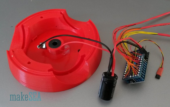
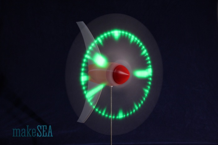
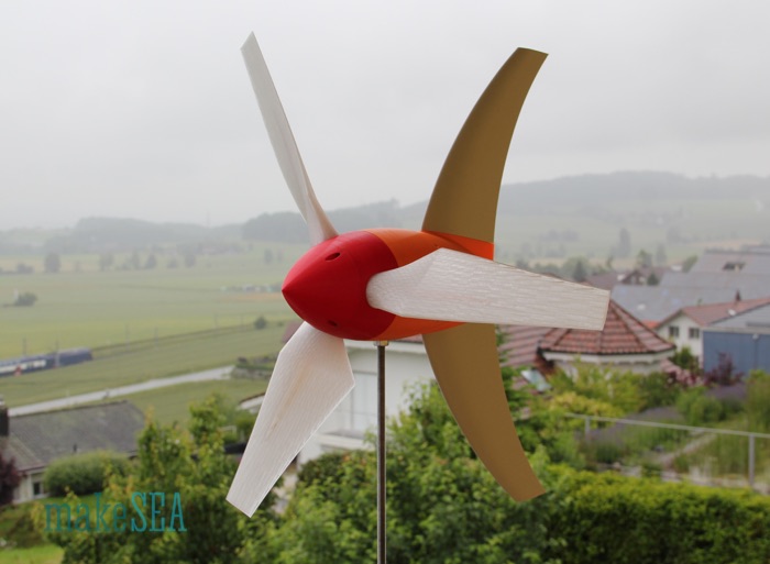
windpowerWriter 3D printed wind turbine/generator
Generator
The generator is based on the brushless motor v2 (makeSEA Model A001.1). The stator of this motor has special heads on its teeth, which guide the wires and simplify the manual work. Because the turbine should charge the capacitor already at low wind speeds, and because it should work with some very simple electronics, it’s required that the generator produces a relative high voltage at low rotation speeds (low value of Kv). A common solution are stator-coils with many turns (and therefore thin wires). In addition to the turns it helps to have stronger magnets (on rotor). The ambitious goal is a Kv value less than 100 RPM/V.Rotor
Because I had many spare magnets in various dimensions (experiments from designing the brushless motor), I reused the 2mm thick magnets. Actually they are 1.85mm thick, and a stack of 2 magnets (3.70mm) are only a little bit thicker than the single 3mm magnets (2.76mm). Together they are also a bit stronger (maybe 10-20%). The win isn’t really big, so the rotor of the brushless motor could also be used, but since the magnet thickness is a simple parameter in my Fusion 360 design, it was easy to change it and 3d-print a new rotor.Stator
The concept of the generator stator is based on the earlier experiments for the brushless motor. The very first version had a Kv by far too high, and I needed to increase the number of turns for the coils. The result then was Kv = 1’000 RPM/V. That’s still 10 times too high compared with the goal.| Wire Diameter |
0.21
| mm |
| Turns per Coil |
63
| |
| Wire Length per Coil |
6’150
| mm |
| Amplitude single Coil (measured) |
1.325
| V |
| Rotation Speed (measured) |
1’054
| RPM |
| Kv (calculated) |
80.5
| RPM / V |
The finished stator has 3 * 6 * 64 = 1’152 turns. With 36 teeth it’s 32 turns per tooth. The generator is ready for extensive measurements and tough tests.
Measurements
The initial measurement of Kv was done in the same way as before with drill and scope. The calculated values could be confirmed. The measured amplitude was 13.7 V and frequency was 101 Hz. Mission seems accomplished ...Here are the basic measurements and characteristics of the generator:
| Resistance per Phase |
19.50
| Ohm |
| Inductance per Phase (may be relevant for the charger) |
650
| mH |
| Kv |
77.6
| RPM / V |
| Nominal Speed (5 m/s wind, 500 mm propeller pitch) |
600
| RPM |
| Nominal Voltage (at nominal speed) |
8.14
| V |
Of course the generator works as well with higher RPM (with storm-winds), but so far the generator behavior at low wind speeds is more important.
The Kv figure doesn’t tell much about the real efficiency as a generator, when it’s charging a big capacitor (or a battery). Because I didn’t have an appropriate / measurable load ready for this test, I was using this generator as a motor. Load means, that there is some power produced - Voltage and Current in the copper wires needs to be different than zero. Motor and generator are reciprocal anyway. As load I used my well known propeller with 10 inch diameter and 4.5 inch pitch. It wasn’t surprising, that the motor doesn’t rotate very fast, if the 6 cell NiMH battery with 7.2V was used. In fact the motor didn’t even start rotating on it’s own, but with a gentle kick by hand it worked. The problem with getting started isn’t the motor, but the combination with the ESC and the battery. Compared with the regular motor, the system behaves as if the RC car was driven with only a single and almost empty cell NiMH. So I have done these tests also with another ESC from a RC car, which runs at 6S LiPo (roughly 24V). With the higher voltage (and the other ESC) the motor could start spinning without issues.
Propeller constante: 1.63E-09 [N*m/RPM^2] … the number was calculated from previous measurements with the brushless motor at much higher RPM. This number is now very useful to calculate the power at low rotation speeds, because it wasn’t possible to measure the torque (the resolution of my scale is too bad).
6 cell NiMH
|
6S LiPO
| ||
| Battery Voltage |
7.40
|
22.80
| V |
| Speed (no load) |
556
|
1’730
| rpm |
| Battery Current I0 (no load) |
0.035
|
0.02
| A |
| Speed (with Propeller) |
545
|
1’615
| rpm |
| Battery Current (with propeller) |
0.04
|
0.055
| A |
| Battery Power (with propeller) |
0.3
|
1.25
| W |
| Shaft Power (with propeller) |
0.03
|
0.72
| W |
| Efficiency (with propeller) |
9%
|
57%
|
| Efficiency (bavaria calculator) |
n.a.
|
56%
| |
| Efficiency Maximum at 0.1 A (bavaria calculator) |
32%
|
70%
|
The similarity of the calculated efficiency and the measured efficiency with 6S LiPo is amazing. It means that the ESC doesn't have much losses (no wonder - it’s designed for 100A continuous load). The result for the lower voltage isn’t reliable: the measurements of the current are at the limit of the resolution of my instruments, and if the ESC had losses of only 1W, it would distort the results a lot.
Finally I’ve done a last measurement with 6 red LEDs as a simple load. A red LED lights up very bright already at 1.8V. With the 3 phase generator it is possible to make a knight-rider flashing light.
The LEDs light up already, if I manually turn the rotor with very little effort. Anyway I’ve fixed the generator in my drill-press rotating at only 200 RPM and took a photo while moving my camera across the LED-bar. With the camera exposure time, light during a period of several milliseconds is collected. The blurred image shows, how the individual LEDs light up in serial sequence due to the 120° shifted phases of the generator (if they would light up all at the same time, the LEDs would appear horizontally arranged). Hello Blinky! ...
Conclusion
I expect that this generator will perform very well at low RPM. The output power will be sufficient for a microcontroller and some LEDs at 5 m/s wind speed. The maximum charging power is unclear. Due to the huge manual winding effort, I would consider to do less turns and use some more sophisticated electronics (with integrated step-up converter).Rectifier/Charger v0
The thing I’m going to create here is a very simplistic rectifier / charger with inferior efficiency. The whole Wind Turbine is quite a complex system. It makes sense to get all the components basically working, and then improve the weakest element. So I decided to build a 3-phase rectifier with 6 regular diodes.Circuit Scheme
Actually I could have drawn this simple circuit by hand, but I found a great online tool , which also has nice simulation features included. The use is very intuitive, and it’s for free - it only costs, if you order a finished PCB.The generator is modeled with 3 AC voltage sources at 8 V amplitude and 100 Hz frequency. For the internal resistance of the generator, there are 3 resistors with 20 Ohm. Large capacitors need to be carefully charged - especially a specific voltage must not be exceeded. For this reason I’ve added a common 5 V regulator, which requires C1 and C2 at it’s in- and output. The LED indicates, if there is voltage at the output. I’ve used a bright green low-power LED with a large resistor (20 kOhm). Basically it’s not useful to have such a permanent consumer-LED in a low power application, and maybe I’ll remove that LED, when the whole thing is working. In reality I’ll have a 500 F capacitor to store the energy, but for the current tests I needed something smaller which quicker indicates, if it’s working: the “big” charged capacitor in this test-circuit has a capacity of only 1 mF (500’000 times less).
The circuit has some basic flaws: The voltage regulator can handle input voltage up to 40 V. With strong winds, the generator can produce much more, and the regulator will probably blow up. The regulator also doesn’t have a heat-sink for cooling - with only a small load, it should survive. If the big capacitor is completely empty, and there are stronger winds, the charging current could be very high for a longer time. The relative high resistance of the generator coils will luckily limit the current (at 0.5A load the generator heats up with a rate of 30W). More power can’t be expected with small propeller blades. In this case it’s good to have inferior efficiency at the generator (which is well cooled), so it won’t burn anything else.
The simulation shows the voltage at 3 selected points (probes 1..3). First directly one of the generator wires (blue), then after the rectifier (red), and finally the output (yellow).
Initially all capacitors are not charged (0V). The output voltage (yellow) increases up to 5 V, and then it remains stable. While it’s increasing, the big capacitor is charged. During that time the voltage at the generator wires (blue) and the rectified voltage (red) have a small constant offset from the output voltage. This offset is roughly 1.5V and is caused by the voltage regulator, which draws as much as possible current from the generator and the generated voltage is lost inside the generator. As soon as the big capacitor is fully charged, the load decreases, and the generator voltage can further increase. It increases depending on the actual rotation speed, and can be calculated based on Kv.
Soldering the PCB
Tests
Guess the testing setup!? Yes - drill and scope: For the initial test I didn’t connect the big capacitor. Just the basic rectifier, with its LED and some smaller caps on-board. Hence the charging-process is very quick. I quickly pushed the drill throttle, but on the scope it’s still visible, that it needs some time until the drill rotates at final speed.
The green curve is one wire directly at the generator, the yellow curve is the output signal. The rectified signal is missing (my scope has only 2 channels). Differently to the simulation, the generator amplitude and frequency is ramping up until it has full speed. This makes it a bit difficult to interpret the charging process of the capacitor. Anyway, it’s visible that the voltage regulator does its job, and limits the output at 5V.
Then I’ve connected a 4F capacitor as a load to be charged. Charging takes much longer.
The ramp-up of the drill speed is no longer relevant, however it takes MUCH more time to observe the charging process. I’ve done two measurements: first snapshot when the capacitor isn’t charged, and the second snapshot 2 Minutes later, when the capacitor is full.
The green line shows again the voltage at the generator, but the yellow curve is now showing the rectified signal. The output stays stable at 5V anyway and isn’t displayed. The measurements remind on the simulation result: while the capacitor is being charged, the voltage is not much above the output signal (which is around 3-4 volts at that time). Later when the capacitor is fully charged the rectified voltage increases up to 12V.
Conclusion
The simple rectifier with 6 diodes and a 5V regulator is good enough for a first try. If electronics breaks due to overvoltage during a stronger storm, there is not much time and money lost. Maybe the propeller blades are even weaker … improvements can be done later.Rectifier/Charger v1
The problem of the simplistic circuit v0: it only works, if the super caps are almost fully charged. If the super caps are only half loaded, it doesn’t work. And there is another problem, when there is too much wind.Step-up Converter and Passive Dump Load
As a solution a step-up converter can be used. There are very cheap and efficient modules available from Ebay or Aliexpress, which convert 0.9V (or even less) into 5.0V with very good efficiency. It’s basically designed to make an USB-charger from a single 1.5V AA battery.The modified circuit doesn’t look much different than the prior version, but it’s much more efficient.
The 3-Phase rectifier converts the AC signal into a DC signal. It uses Schottky diodes, which have a lower voltage drop than regular diodes. With the DC signal the super caps are charged.
A simple dump-load made of 7 regular diodes limits the loading voltage to roughly 5V (the voltage drop of a single diode is roughly 0.7V). 6V => 275mA, 5V => 20mA, 4V => 0.8mA, 3V => 0.05mA.
The PFM-Module gets the power from the supercaps and converts the voltage to 5V. A low-power LED with a 20kOhm resistor is indicating the output power (it “eats” only 0.1mA).
This charger works amazingly well. Without connecting the supercaps the output LED is already lit, when the generator is rotated only ¼ turn by fast manual move. It’s charging the supercaps below 200RPM, and the PFM module works already at 0.2V input voltage.
Theoretically a lithium battery could also be used instead of the supercaps. But the problem with the battery is the working range between 3.3V and 4.2V. The circuit would need to be changed: the battery needs to be charged by the PFM module.
Active Dump Load
The problem with the simplistic 7 diodes dump-load: the transition from no-load to dump-load is continuous (exponential). It would be better, if the dump-current was zero up until 5V (use all the energy to charge the supercap), and then it should have a steep increase and draw as much current as needed in order to pull down the voltage to 5V, if the generator voltage was higher.The circuit scheme has 3 main blocks:
- The generator-block is a placeholder of the actual generator and the rectifier helping to understand the functionality of the rest of the circuit. Important detail is the resistor as a placeholder of the resistance of the generator coils.
- The block with the 5V limiting dump load contains a green LED (D1), which is used as a voltage reference. It theoretically could be replaced with a 2.5V Zener diode (which I didn’t have available at the moment), but it wouldn’t improve the performance of the circuit anyway. The trick: when the voltage of the generator is increased linearly, the voltage at the positive input of the Op Amp also increases linearly. Differently the voltage at the inverting input of the Op Amp increases logarithmic, because of the diode. Exactly at the point where the two input curves intersect, the output of the opamp goes up from low to high, and the darlington-transistor (Q2) pulls down the supply-voltage. It stays stable at 5V. The darlington-transistor has a TO-220 case. With 200mA it burns 1W and gets slightly warm - with more current it needs a heatsink. Theoretically it could handle a current up to 8A (far more than the generator creates).
- The last block is only a display with an LED (D2) that lights up, if the circuit is dumping superfluous current. The LED and the transistor (Q2) actually operate as well as a little dump-load with the current limited by R6.
Below 5V the circuit with the circuit draws roughly a constant current of 0.25mA (2 x 0.05mA by the voltage divider and the voltage reference, 0.15mA by the Op Amp). At 5V there is a steep increase (depending on the resistance of the cables from my power supply). Below 3.5V the 7-diodes have a better performance: At 2V the Op Amp wastes 100 times more current than the diodes - current, which could be used to charge the supercap. However the absolute value of the current needs to be compared with the current needed finally by the microcontroller. An Arduino Pro Mini with some LEDs connected will need at minimum 5mA, so it’s not relevant if 0.25mA are lost.
As next the circuit would need to be properly soldered on a PCB, but I’ll wait until the rest of the wind turbine is finished (the circuit with the diodes as dump load is good enough for testing).
Testing the Generator and Charge Controller together
Finally! The generator and the Charger v1 with the passive Dump Load are connected (not yet the active Dump load). The generator is fixed on the drill-press (which has luckily a RPM-display). The rectified voltage is measured depending on the generator rotation speed. No capacitor or any other load is connected.Up to 500 RPM the voltage increases approx. linearly until 5V. At higher speeds the voltage is almost flat. That’s the expected effect caused by the passive dump load (7 diodes). Up until 5V the dump-load is not dumping much current - the voltage can increase corresponding to Kv. At higher rotation speeds the diodes are “eating” more and more current. The superfluous energy is then wasted as heat in the diodes and the generator copper wires. If there was no dump-load attached with Kv=80 RPM/V the generated voltage at 2’500 RPM would be at 31V.
Interesting to note: at 200 RPM the generated voltage is around 3V.
The next measurement is the current with the rectified signal short-circuited:
The curve is almost perfectly linear. As expected. The resistance of the generator copper wires is the reason. The induced voltage increases linearly with the rotation speed (U = RPM/Kv), and since the resistance is constant, also the current increases linearly (I = U/R). Assuming 31V at 2500RPM with 800mA current, the generator has a power loss of 25W - all heating up the copper wire. In-deed after only 30 seconds on the drill-press, the stator is remarkably warm.
Interesting to note: at 200 RPM the short-circuit current is over 50mA.
Power/Current Consumption Estimation
How will the system behave with an Arduino attached? Will it be possible to light 20 LEDs, and still charge the capacitor? Which wind speed is needed for “break-even”? How long will it run with fully charged capacitor and no wint? The answers will potentially influence the software requirements for the microcontroller.Arduino Pro Mini 3.3V, 8MHz:
- 20mA running original
- 3mA at boot-up (resistor of red status LED de-soldered)
- 0.5mA running with simple sleep delay (resistor of red status LED desoldered)
- More hacks (power down sleep, 50uA):
LEDs:
- Red LED needs 2V, green or blue needs 2.7V
- Connect with resistor to 3.3V, not possible to have 2 LEDs in series.
- LEDs need to be well selected
- I have a greed LED which appears quite bright with only 0.125mA, however will drive them with 1mA (not all LEDs will be ON at the same time)
Hall Switch (3141):
- Datasheet: supply voltage 4.5V .. 28V
- Datasheet: supply current 4.4mA .. 9mA ⇒ that’s a lot compared with the rest
⇒ high power consumption, use additional transistor to turn it on or off
⇒ evaluate magnetic reed-switch?
- Test at 5.0V: draws 3.2mA .. 4.3mA
- Test at 3.3V: draws 2.8mA .. 3.6mA ⇒ :-) that’s my choice (even if it’s out of specs)
- Test at 2.7V: draws 1.8mA .. 2.0mA
- Test at 2.6V: Works “analog” no switching trigger point
- Test at 2.5V: Works “analog”
- Test at 2.4V: Fail
Conclusion
The whole system consumes 3.3mA .. 5.0mA if the LEDs are OFF. At maximum 26mA if all LEDs are ON. The generator produces 3V and 50mA at 200 RPM, which corresponds to 1.7m/s (6km/h) wind speed. Wind as fast as walking speed should be enough to charge the capacitor and drive the microcontroller together. Or even better: 1 hour of walking speed wind should theoretically produce enough energy for powering the microcontroller more than 10 hours. Let’s see …For demonstration I’ve connected all with an Arduino Pro Mini. In the video I’m turning the generator with my hand (very slowly). The green LED on the charge controller lights up, and the red LED on the Arduino is flashing randomly and bright while it’s booting. Once booting is finished, my program starts running. The program on the Arduino does a short double-flash with the red LED every two seconds. In-between the arduino is sleeping.
Components: Wind Turbine
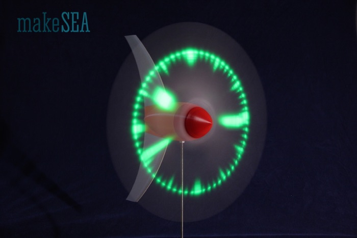
Summary
This Wind Turbine is not just a Wind Turbine. Wind is driving a 3d-printed propeller and a 3d-printed generator. The generator charges a super-capacitor (or a battery), and produces electricity for an Arduino, which sits in the 3d-printed propeller hub. The Arduino switches on and off an array of LEDs located in the blades. If the propeller is spinning at a certain speed, the blinking LEDs will paint an image into the air. It can display various messages (e.g. wind-speed or the time).Of course this display is difficult to read during the day with glaring sun-light, or if there is no wind. Anyway it’s a demonstration of the future - the Internet of Things is coming: there will be a web-server inside the propeller-hub, the energy stored in the battery will be used for communication. Users will be able to browse this Wind Turbine with their Smartphone. They will obtain weather information, and they will be able to post their tweets onto the propeller, even if there is no wind … ;-)
With this project I wanted to create something, which is crafted mainly by using the new element: 3d-printing filament! Components, which are not 3d-printable should be minimized, and they should be very basic: copper-wire, magnets, screws. Intelligence is inserted into this system by using an Arduino. All the project details are open-source, published on makeSEA.com. People with a 3d-printer, a solder iron, and an Arduino in their workshop should be able to “download” this Wind Turbine, or parts of it.
I’d like to sensibilize people, that the world of today has a heart, and humans are responsible for it. A smart-phone is not smart - the inventor of this phone is smart! We all are humans, and we should consider our potential. The Wind Turbine demonstrates the use of ecological energy. It’s an autonomously working gadget. Eco friendliness, luxury, and fun are partners. The reason how the Wind Turbine works is not just magic - it’s simple physics and not religion. If somebody walks through this project, he (or she) will have a different view at the “modern” gadgets. I’d like to encourage people to not just stack huge and complex building blocks on top of an unknown base. It could be very dangerous, the system behaves unpredictably and operates very inefficient. Look behind the scenes and have fun!
System
The wind turns the propeller and the direct driven generator. The generator produces 3-phase AC voltage. The AC is then rectified, and limited to 5V. The overvoltage is “burned” (dump-load) in order to prevent overloading the super capacitors. A step-up converter creates constant 5V even if capacitors are not yet fully charged. In the propeller hub there is an Arduino, which controls 7 LEDs in each blade. A Hall-Sensor triggers a signal with each full revolution, and the Arduino uses this signal in order to turn on or off LEDs, and “paint” a stable pattern with the LEDs.
Rectifier, Charge-Controller and Step-Up-Converter are all on a single PCB. For simplicity I’ll often name this PCB only Charge-Controller.
Main Components
These are the main 3d-printable (exterior) components for the Wind Turbine. They are held together with 17 screws. Most parts can be printed without support. Support is needed for the tower parts, house front, hub back. Printing orientation: largest flat surface oriented towards print-bed.
Internal Components
Descriptions about the generator and the charge controller can be found in the other documents about the development of these internal components (“Wind Turbine internal Components”). Maybe I’ll merge these files later ...
If one long shaft is used connecting generator and propeller hub directly, the back ball bearing in the house and the front ball bearing in the generator are not needed.
Sliding Tracks:
Sliding tracks minus pole: (ab-) using a ball bearing (next to generator):
4. The washer needs to be level or flush with the housing so that when the turbine turns it will not “wiggle” -D.Hartley
5. If you do not have a good wire stripper to strip thin wires, then I would recommend using a lighter to light the end of the wire and just pull the plastic off. It works great, but be careful! To avoid problems, I would recommend soldering each negative lead of the LED together with 14 mm of spacing for each blade (3 sets of 7 LEDs). Then I would start from the top of the LEDs and solder the thin wire to the positive lead of the LED and weave the wire around the rest of the LEDs (shown above). The wire needs to extend from the last LED at least the length of the LEDs soldered together, but it can be longer, you just might have to cut it later. Once all seven of one strand of LEDs are soldered with wires then shrink tube at least half the length of the wire extending from the last LED. This will make it easier to manage the wires in the housing. Do this again for the other two strands of LEDs. Once all of the LEDs are wired and shrink tubed, then you are good to move on. -D. Hartley
Arduino: We are using the 8MhZ, 3.3V version:
When using A6 as input for the Hall-Switch, a pull-up resistor 4k7 is needed.7
6. For this step, you will need 22 180 Ohm resistors. You will also need to connect the PCB to ground terminals on the Arduino using leftover parts from cutting the resistors. In total, 3 ground terminals will be wired to the PCB, and 22 Resistors will be connected to terminals TX0, Rx1, 2-13, and A0-A7. 20 of these terminals will be wired to LEDs. The ones that are not wired to LEDs are A6 and A7. A6 is wired to the Hall-Switch, and A7 is not wired to anything. -D. Hartley
7. The 4k7 resistor is soldered to VCC and A6. -D. Hartley
8. A6 (only) for the Hall Switch.
9. I would not recommend doing it this way as it will take time to go through each wiring of the LED and line it up with the code. Also using different colored wires helps a ton. -D. Hartley
Magnet and Hall-Switch:
More on the Installation of the Capacitors and How they Work:
A capacitor (or also a battery) can be compared with a reservoir. The water pressure corresponds to the voltage. Water flow (gallons/sec) corresponds to the current. A water pump makes the water flowing through the pipes - pressure at the output is higher that at the input.
For the life-demo I've added the switch, because the arduino would always run, and people couldn't recognize, that the generator is actually working when there is wind. And if the supercaps are completely empty it takes a wile, until they are charged at the minimum level required for the step-up-converter.
Software
- Text (or image) is rendered into a global pixmap with polar coordinate axis. 7 pixels as radius, and a specified number of pixels as angle (depends on the rotation speed and power of the micro-controller). One byte is used for the radial dimension (each bit for one LED - 1 bit is unused).
- Measure the time per revolution. Depending on the current time, the current angle of the propeller blade(s) can be calculated.
- The blade-angle is used to calculate the pixel-index, and LEDs are switched on or off depending on the pixmap content.
- The global pixmap is changed occasionally with alternating text, patterns, or actual measurements.
Frequently Asked Questions (FAQ)
What is the preferred position to print the blades?
The blades for this project can be printed standing up, assuming you have good plate adheasion. At 100%, this requires a printer with a footprint at least as tall as 10 inches or, 250mm. Supports should work but also are not necessary.
How do you fit the drive shaft on the rotor?
The drive shaft is supported by bearings that are nested in the sheild and hub.Can the blade angle be adjusted. Did you test the influence of their angle at given wind speeds?
The blades in the current design are slightly oval at the base and prefer a fixed, optimized position based on arodynamics to produce the least drag possible at low wind speed. The Arduino code is programmed accordingly. The blades can be adjusted but there will be a slight gap between the front and rear of the hub. This can be modified using the supplied source files. Larger blades, or high-wind conditions may benefit from some adjustment for optimal performance.XXX . V0 Improving wind turbine power conversion in variable speed wind turbines
A new section where authors highlight their peer-reviewed research published in Renewable Energy Focus Journal begins with a novel solution that could potentially protect Variable Speed Wind Turbine Doubly Fed Induction Generator converters during grid fault scenarios.

The proposed T-type Grid Side Converter (GSC) DFIG converter scheme in the research paper is much easier to achieve with less switching circuitry when compared to the conventional 3-level multilevel converters
The proposed T-type Grid Side Converter (GSC) DFIG converter scheme in the research paper is much easier to achieve with less switching circuitry when compared to the conventional 3-level multilevel converters. Also, this scheme avoids the use of an external traditional expensive control strategy in achieving DFIG wind farm stability during grid disturbance.
The proposed converter topology for DFIG wind generators creates room for a sophisticated and robust converter controller implementation that would protect the fragile, vulnerable VSWT DFIG converters during grid fault scenarios.
Consequently, it would enable modern wind farms taking advantage of DFIG to remain grid connected - based on the grid codes or requirements to supply power to utilities during occurrences of “transients” - instead of having to disconnect from the grid. Also, instead of phasing out earlier wind turbines using the fixed speed technology, wind farms in the future could be composed of both fixed and variable speed wind turbines. This is because the variable speed wind turbines could help stabilise the fixed speed wind turbines and the entire wind farm during grid disturbances, at a lower cost, and without requiring expensive external reactive power compensators.
I give some more broad, technical details
Amongst the various renewable energy sources, the use of wind energy is very common, considering the technological advancement of wind turbines and power electronics applications.
The common wind turbines either use Fixed Speed Wind Turbines (FSWT), made of the Squirrel Cage Induction Generator (SCIG) technology; or the Variable Speed Wind Turbine (VSWT), made of the Doubly Fed Induction Generator (DFIG)/Permanent Magnetic Synchronous Generator (PMSG).
The response of wind generators to grid disturbances is an important issue nowadays due to increased wind on the grid. Therefore, it is important that utilities and grid companies study the effects of various voltage sags on the corresponding wind turbine responses. Grid codes or requirements were formulated with the effective operation of grid-connected wind farms in mind. Such emerging grid codes demand that wind farms should have a good performance with respect to voltage control capability, and robust behaviour against frequency and voltage variations under fault condition.
The SCIG is used in general for FSWT generators due to its superior characteristics (i.e. brushless and rugged construction; low cost; maintenance free; and operational simplicity). However, it requires large reactive power to recover the air gap flux when a short circuit fault occurs in the power system. Therefore, reactive power compensation from power network or other devices is needed for a FSWT wind farm. The installation of compensation units in FSWT farms to overcome voltage sag during a grid fault (like static synchronous compensators (STATCOM); superconducting magnetic energy storage (SMES); and energy capacitor system (ECS) increases the system overall cost.
In general, the amount of the necessary dynamic reactive power compensation depends on the type of wind turbine generator system (WTGS), and is influenced by the relevant electrical and mechanical parameters of that system.
The doubly fed induction generator (DFIG) has very attractive characteristic as a wind generator because the power processed by the converter is only a fraction of the total power rating of the DFIG. This is typically 20%-30%, and therefore its size, cost, and losses are much smaller compared to a full size power converter used in other types of variable speed wind generators.
DFIG can operate at a wide range of speeds (depending on the wind speed or other specific operation requirements). Thus, it allows better capture of wind energy. The dynamic slip control and pitch control are the other salient features which help to augment the system stability. In addition, DFIG has better system stability during short-circuit faults in comparison with IG, because of its capability of independent control of active and reactive power output. This superior dynamic performance of the DFIG results from the frequency converter, which typically operates with sampling and switching frequencies of above 2 kHz. Therefore, it is paramount to use a VSWT system like a DFIG to stabilise a FSWT (IG) in a wind farm, because the DFIG system can also control reactive power in a similar manner to a STATCOM, SMES, or ECS, and thus the reactive power compensation can be implemented at a lower cost.
Why do these findings matter?
The results show improved performance of the DFIG wind generator during transient conditions considering the proposed scheme, thus saving the cost of traditional external expensive circuitry and more switching Insulated Gate Bipolar Transistors (IGBTs) used in the conventional 3-level multilevel converters for the DFIG Fault Ride Through (FRT) capability.
In addition, the simple extension of the conventional 2-level Grid Side Converter (GSC) of the DFIG wind generator to a 3-level topology by the bidirectional middle switch with two Insulated gate Bipolar Transistors (IGBTs) in common emitter connections, leads to low switching losses; low forward voltage drop; and only one more isolated gate drive supply per phase leg; when compared with the conventional 2-level converter.
XXX . V00 Wind turbines
Wind turbines look like airplane propellers running on the spot—spinning round but going nowhere. They're serving a very useful purpose, however. There's energy locked in wind and their giant rotors can capture some of it and turn it instantly into electricity. Have you ever stopped to wonder how wind turbines work? Let's take a closer look!
How does a turbine generate electricity?
Photo: Head for heights! You can see just how big a wind turbine is compared to this engineer, who's standing right inside the nacelle (main unit) carrying out maintenance. Notice how the white blades at the front connect via an axle (gray—under the engineer's feet) to the gearbox and generator behind (blue). Photo by Lance Cheung courtesy of US Air Force.
A turbine, like the ones in a wind farm, is a machine that spins around in a moving fluid (liquid or gas) and catches some of the energy passing by. All sorts of machines use turbines, from jet engines to hydroelectric power plants and from diesel railroad locomotives to windmills. Even a child's toy windmill is a simple form of turbine.
The huge rotor blades on the front of a wind turbine are the "turbine" part. The blades have a special curved shape, similar to the airfoil wings on a plane. When wind blows past a plane's wings, it moves them upward with a force we call lift; when it blows past a turbine's blades, it spins them around instead. The wind loses some of its kinetic energy (energy of movement) and the turbine gains just as much. As you might expect, the amount of energy that a turbine makes is proportional to the area that its rotor blades sweep out; in other words, the longer the rotor blades, the more energy a turbine will generate. Obviously, faster winds help too: if the wind blows twice as quickly, there's potentially eight times more energy available for a turbine to harvest. That's because the energy in wind is proportional to the cube of its speed.
Wind varies all the time so the electricity produced by a single wind turbine varies as well. Linking many wind turbines together into a large farm, and linking many wind farms in different areas into a national power grid, produces a much more steady supply overall.
Key parts of a wind turbine?
Although we talk about "wind turbines," the turbine is only one of the parts inside these machines. For most (but not all) turbines, another key part is a gearbox whose gears convert the relatively slow rotation of the spinning blades into higher-speed motion—turning the drive shaft quickly enough to power the electricity generator.The generator is an essential part of all turbines and you can think of it as being a bit like an enormous, scaled-up version of the dynamo on a bicycle. When you ride a bicycle, the dynamo touching the back wheel spins around and generates enough electricity to make a lamp light up. The same thing happens in a wind turbine, only the "dynamo" generator is driven by the turbine's rotor blades instead of by a bicycle wheel, and the "lamp" is a light in someone's home miles away. In practice, wind turbines use different types of generators that aren't very much like dynamos at all. (You can read about how they work, more generally, in our main article about generators.)
How does a wind turbine work?
- Wind (moving air that contains kinetic energy) blows toward the turbine's rotor blades.
- Wind (moving air that contains kinetic energy) blows toward the turbine's rotor blades.
- The rotors spin around, capturing some of the kinetic energy from the wind, and turning the central drive shaft that supports them. Although the outer edges of the rotor blades move very fast, the central axle (drive shaft) they're connected to turns quite slowly.
- In most large modern turbines, the rotor blades can swivel on the hub at the front so they meet the wind at the best angle (or "pitch") for harvesting energy. This is called the pitch control mechanism. On big turbines, small electric motors or hydraulic rams swivel the blades back and forth under precise electronic control. On smaller turbines, the pitch control is often completely mechanical. However, many turbines have fixed rotors and no pitch control at all.
- Inside the nacelle (the main body of the turbine sitting on top of the tower and behind the blades), the gearbox converts the low-speed rotation of the drive shaft (perhaps, 16 revolutions per minute, rpm) into high-speed (perhaps, 1600 rpm) rotation fast enough to drive the generator efficiently.
- The generator, immediately behind the gearbox, takes kinetic energy from the spinning drive shaft and turns it into electrical energy. Running at maximum capacity, a typical 2MW turbine generator will produce 2 million watts of power at about 700 volts.
- Anemometers (automatic speed measuring devices) and wind vanes on the back of the nacelle provide measurements of the wind speed and direction.
- Using these measurements, the entire top part of the turbine (the rotors and nacelle) can be rotated by a yaw motor, mounted between the nacelle and the tower, so it faces directly into the oncoming wind and captures the maximum amount of energy. If it's too windy or turbulent, brakes are applied to stop the rotors from turning (for safety reasons). The brakes are also applied during routine maintenance.
- The electric current produced by the generator flows through a cable running down through the inside of the turbine tower.
- A step-up transformer converts the electricity to about 50 times higher voltage so it can be transmitted efficiently to the power grid (or to nearby buildings or communities). If the electricity is flowing to the grid, it's converted to an even higher voltage (130,000 volts or more) by a substation nearby, which services many turbines.
- Homes enjoy clean, green energy: the turbine has produced no greenhouse gas emissions or pollution as it operates.
- Wind carries on blowing past the turbine, but with less speed and energy (for reasons explained below) and more turbulence (since the turbine has disrupted its flow).
How turbines harvest maximum energy
If you've ever stood beneath a large wind turbine, you'll know that they are absolutely gigantic and mounted on incredibly high towers. The longer the rotor blades, the more energy they can capture from the wind. The giant blades (typically 70m or 230 feet in diameter, which is about 30 times the wingspan of an eagle) multiply the wind's force like a wheel and axle, so a gentle breeze is often enough to make the blades turn around. Even so, typical wind turbines stand idle about 14 percent of the time, and most of the time they don't generate maximum power. This is not a drawback, however, but a deliberate feature of their design that allows them to work very efficiently in ever-changing winds. Think of it like this. Cars don't drive around at top speed all the time: a car's engine and gearbox power the wheels as quickly or slowly as we need to go according to the speed of the traffic. Wind turbines are analogous: like cars, they're designed to work efficiently at a range of different speeds.A typical wind turbine nacelle is 85 meters (280 feet) off the ground—that's like 50 tall adults standing on one another's shoulders! There's a good reason for this. If you've ever stood on a hill that's the tallest point for miles around, you'll know that wind travels much faster when it's clear of the buildings, trees, hills, and other obstructions at ground level. So if you put a turbine's rotor blades high in the air, they capture considerably more wind energy than they would lower down. (If you mount a wind turbine's rotor twice as high, it will usually make about a third more power.) And capturing energy is what wind turbines are all about.
Since the blades of a wind turbine are rotating, they must have kinetic energy, which they "steal" from the wind. Now it's a basic law of physics (known as the conservation of energy) that you can't make energy out of nothing, so the wind must actually slow down slightly when it passes around a wind turbine. That's not really a problem, because there's usually plenty more wind following on behind! It is a problem if you want to build a wind farm: unless you're in a really windy place, you have to make sure each turbine is a good distance from the ones around it so it's not affected by them.
Photo: This unusual Darrieus "egg-beater" wind turbine rotates about a vertical axis, unlike a normal turbine with a horizontal rotor. Its main advantage is that it can be mounted nearer to the ground, without a tower, which makes it cheaper construct. It can also capture wind coming from any direction without using things like pitch and yaw motors, which makes it simpler and cheaper. Even so, turbines like this suffer from a variety of other problems and are quite inefficient at capturing energy, so they're very rare. Photo by courtesy of US Department of Energy.
Advantages and disadvantages of wind turbines
Drawbacks
At first sight, it's hard to imagine why anyone would object to clean and green wind turbines—especially when you compare them to dirty coal-fired plants and risky nuclear ones, but they do have some disadvantages.One of the characteristics of a wind turbine is that it doesn't generate anything like as much power as a conventional coal, gas, or nuclear plant. A typical modern turbine has a maximum power output of about 2 megawatts (MW), which is enough to run 1000 2kW electric toasters simultaneously—and enough to supply about 1000 homes, if it produces energy about 30 percent of the time. The world's biggest offshore wind turbines can now make 6–8 megawatts, since winds are stronger and more persistent out at sea, and power about 6000 homes. In theory, you'd need 1000 2MW turbines to make as much power as a really sizable (2000 MW or 2GW) coal-fired power plant or a nuclear power station (either of which can generate enough power to run a million 2kW toasters at the same time); in practice, because coal and nuclear power stations produce energy fairly consistently and wind energy is variable, you'd need rather more. (If a good nuclear power plant operates at maximum capacity 90 percent of the time and a good, brand new, offshore wind farm manages to do the same 45 percent of the time, you'd need twice as many wind turbines to make up for that.) Ultimately, wind power is variable and an efficient power grid needs a predictable supply of power to meet varying demand. In practice, that means it needs a mixture of different types of energy so supply can be almost 100 percent guaranteed. Some of these will operate almost continually (like nuclear), some will produce power at peak times (like hydroelectric plants), some will raise or lower the power they make at short notice (like natural gas), and some will make power whenever they can (like wind). Wind power can't be the only form of supply—and no-one has ever pretended that.
As we've just seen, you can't jam a couple of thousand wind turbines tightly together and expect them to work effectively; they have to be spaced some distance apart (typically 3–5 rotor diameters in the "crosswind" direction, between each turbine and the ones either side, and 8–10 diameters in the "downwind" direction, between each turbine and the ones in front and behind). Put these two things together and you arrive at the biggest and most obvious disadvantage of wind power: it takes up a lot of space. If you wanted to power an entire country with wind alone (which no-one has ever seriously suggested), you'd need to cover an absolutely vast land area with turbines. You could still use almost all the land between the turbines for farming; a typical wind farm removes less than 5 percent of land from production (for the turbine bases, access roads, and grid connections). You could mount turbines out at sea instead, but that raises other problems and costs more. Even onshore, connecting arrays of wind turbines to the power grid is obviously a bigger hurdle than wiring up a single, equivalent power plant. Some farmers and landowners have objections to new power lines, though many earn handsome profits from renting out their land (potentially with a guaranteed income for a quarter of a century), most of which they can continue to use as before.
Advantages
On the plus side, wind turbines are clean and green: unlike coal stations, once they're constructed, they don't make the carbon dioxide emissions that are causing global warming or the sulfur dioxide emissions that cause acid rain (a type of air pollution). Once you've built them, the energy they make is limitless and (except for spare parts and maintenance) free over a typical lifetime of 25 years. That's even more of an advantage than it sounds, because the cost of running conventional power plants is heavily geared to risky things like wholesale oil and gas prices and the volatility of world energy markets.Wind turbine towers and nacelles contain quite a bit of metal, and concrete foundations to stop them falling over (a typical turbine has 8000 parts in total), so constructing them does have some environmental impact. Even so, looking at their entire operating lifespan, it turns out that they have among the lowest carbon dioxide emissions of any form of power generation, significantly lower than fossil-fueled plants, most solar installations, or biomass plants. Now nuclear power plants also have relatively low carbon dioxide emissions, but wind turbines don't have the security, pollution, and waste-disposal problems many people associate with nuclear energy, and they're much quicker and easier to construct. They're also much cheaper, per kilowatt hour of power they produce: half the price of nuclear and two thirds the price of coal (according to 2009 figures quoted by Milligan et al). According to the Global Wind Energy Council, a turbine can produce enough power in 3–6 months to recover the energy used throughout its lifetime (constructing, operating, and recycling it).
In summary
Pros
- Very low carbon dioxide emissions (effectively zero once constructed).
- No air or water pollution.
- No environmental impacts from mining or drilling.
- No fuel to pay for—ever!
- Completely sustainable—unlike fossil fuels, wind will never run out.
- Turbines work almost anywhere in the world where it's reliably windy, unlike fossil-fuel deposits that are concentrated only in certain regions.
- Unlike fossil-fueled power, wind energy operating costs are predictable years in advance.
- Freedom from energy prices and political volatility of oil and gas supplies from other countries.
- Wind energy prices will become increasingly competitive as fossil fuel prices rise and wind technology matures.
- New jobs in construction, operation, and manufacture of turbines.
Cons
- High up-front cost (just as for large nuclear or fossil-fueled plants).
- Economic subsidies needed to make wind energy viable (though other power forms are subsidised too, either economically or because they don't pay the economic and social cost of the pollution they make).
- Extra cost and complexity of balancing variable wind power with other forms of power.
- Extra cost of upgrading the power grid and transmission lines, though the whole system often benefits.
- Variable output—though that problem is reduced by operating wind farms in different areas and (in the case of Europe) using interconnectors between neighboring countries.
- Large overall land take—though at least 95 percent of wind farm land can still be used for farming, and offshore turbines can be built at sea.
- Can't supply 100 percent of a country's power all year round, the way fossil fuels, nuclear, hydroelectric, and biomass power can.
- Loss of jobs for people working in mining and drilling.
But what if the wind doesn't blow?
Some people worry that because wind is very variable, we might suddenly lose all our electricity and find ourselves plunged into a "blackout" (a major power outage) if we rely on it too much.The reality of wind is quite different. "Variable" does not mean unreliable or unpredictable. Wherever you live, your power comes from a complex grid (network) of intricately interconnected power-generating units (ranging from giant power plants to individual wind turbines). Utility companies are highly adept at balancing power generated in many different places, in many different ways, to match the load (the total power demand) as it varies from hour to hour and day to day. The power from any one wind turbine will fluctuate as the wind rises and falls, but the total power produced by thousands of turbines, widely dispersed across an entire country, is much more regular and predictable. For a country like the UK, it's pretty much always windy somewhere. As Graham Sinden of Oxford University's Environmental Change Institute has shown, low wind speeds affect more than half the country for only 10 percent of the time; for 60 percent of the time, only 20 percent of the UK suffers from low wind speeds; and only for one hour per year is 90 percent of the UK suffering low speeds (Sinden 2007, figure 7). In other words, having many wind turbines spread across many different places guarantees a reasonably steady supply of wind energy virtually all year round.
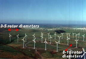
Photo: You can put lots of turbines together to make a wind farm, but you need to space them out to harvest the energy effectively. Combining the output from many wind farms in many different areas produces a smoother and more predictable power supply. This wind farm is at one of the world's windiest places: Altamont Pass, California, United States. Photo by courtesy of US Department of Energy.
While it's true that you might need 1000 wind turbines to produce as much power as a giant coal or nuclear plant, it's also true that if a single wind turbine fails or stops turning, it causes only 1/1000th (0.1 percent) of the disruption you get when a coal or nuclear plant fails or goes offline for maintenance (which happens more often than you might think). It's also worth bearing in mind that wind is relatively predictable several days in advance so it's easy for power planners to take account of its variability as they figure out how to make enough power to meet expected demands.
Opponents of wind power have even suggested that it might be counter-productive, because we'd need to build extra backup coal, nuclear, biomass, or hydro plants (or some way of storing wind-generated electricity) for those times when there's not enough wind blowing. That would certainly be true if we made all our energy from one, single mega-sized wind turbine—but we don't! In reality, even countries that have large supplies of wind energy have plenty of other sources of power too; as long as wind power is making less than half of a country's total energy, the variability of the wind is not a problem. (Denmark, for example, makes 20 percent of its electricity—and meets 43 percent of its peak load—with wind; Eric Martinot's article "How is Denmark Integrating and Balancing Renewable Energy Today?" gives an excellent overview of how that country has managed to integrate huge amounts of wind power into its grid.) In practice, every country's electricity has always come from a mixture of different energy sources, and the ideal mix varies from one country to another for geographical, practical, and political reasons.
How can we store the power of the wind?
Photo: How pumped storage works: When there's lots of cheap electricity about (at night or when the wind is blowing), water is pumped up the mountain to the high-level lake at low cost. When electricity is more expensive and valuable (in the day, at peak times), the water drains from the high lake to the low one, powering a hydroelectric turbine.
Wind could play a bigger part in the future if we could find cost-effective ways of storing electricity produced on windy days for times when there's little or no wind to harvest. One tried and tested possibility is pumped storage: low-price electricity is used to pump huge amounts of water up a mountain to a high-level lake, ready to be drained back down the mountain, through a hydroelectric turbine, at times of high demand when the electricity is more valuable. (In effect, we store electricity as gravitational potential energy, which we can do indefinitely, and turn it back to electricity when it suits us.)
Batteries could also be a contender—if we had enough of them. There have been suggestions about using a fleet of electric cars as a giant collective battery, for exactly this purpose, but even large-scale batteries hooked up to individual wind farms could be very helpful. Statoil, for example, plans to install a huge wind-powered battery called BatWind in Scotland. Flywheels (heavy, low-friction wheels that store energy as they spin) are another possibility.
Is wind the energy of the future?
It certainly has a part to play, but how big a part depends on where in the world you are and whether there are better alternatives suited to your local geography. In sunny Australia, for example, solar would probably be cheaper. In countries that have windy winters (when electricity demand is at its highest), wind turbines could be a strong contender; on August 11, 2016, for example, wind turbines in (windy) Scotland produced enough energy to power the whole country. Countries with lots of fossil-fueled plants and no plans to retire them soon might find investments in carbon capture and storage (scrubbing the carbon dioxide from the emissions of coal and other fossil plants) a wise option, though that remains a largely unproven technology. Ultimately, it's a political choice as well as a scientific one. In Germany, where people have strong opposition to nuclear power, there have been huge investments in wind energy. Denmark, another European country, plans to move to 100 percent renewable energy with a massive commitment to wind. Although China is investing heavily in wind power, it still makes about three quarters of its electricity from coal. In short, while the growth of wind power is impressive, it still plays a relatively small part, overall, in providing the world's electricity.Chart: Which countries are making the most of their wind? It's no surprise to find the biggest countries (China, the United States, and India among them) topping the list of countries with the most installed wind capacity, measured in gigawatts. But if we measure installed capacity per capita, we get this very different chart. Now European countries such as Denmark, Sweden, and Germany lead the pack, the United States is 10th, China manages only 20th place, and India comes in at number 32. Drawn by Explainthatstuff.com using 2015 wind capacity data courtesy of the Global Wind Energy Council and 2015 population data compiled by the World Bank.
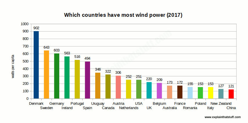
Micro-wind turbines
Photo: Micro power to the people! This small, mast-mounted Rutland Windcharger is designed to trickle-charge 12V and 24V batteries, such as those used in small boats, far from the grid. At a wind speed of 40–55 km/h (20–30 knots), it will produce a handsome 140–240 watts of power. At 20 km/h (10 knots), it produces a rather more modest 27 watts.
If small is beautiful, micro-wind turbines—tiny power generators of about 50–150 W capacity, perched on a roof or mast—should be the most attractive form of renewable energy by far. They're certainly very widely used for all kinds of portable power, typically for recharging batteries in things like yachts and canal boats, and for powering temporary traffic lights and road signs.
Some manufacturers have pushed micro-wind technology aggressively, hinting that people could make big savings on electricity bills, and benefit the environment, by putting a little turbine on their roof to feed energy into the national power grid. The reality is a bit different: micro-turbines linked to the grid do indeed bring economic and environmental benefits if they're sited in reliably windy areas, but they're less helpful in towns and cities where buildings make "energy harvesting" more of a challenge and there's much more turbulence from obstructions. So are micro-wind turbines really worth the investment? How do they compare with their big brothers?
How micro-wind turbines compare
These figures are simply designed to give a rough comparison of the differences between large-scale and micro-wind turbines. Bear in mind that there's a huge variety of micro-turbines.
| Large | Micro | |
|---|---|---|
| Mounting | Tower roughly 80–100m (260–344ft) high. | Roof, or mast typically ~10m (30ft) high. |
| Rotor diameter | Up to 90m (300ft). | 1–4m (3–12ft). |
| Energy production | 1–8 megawatts (1000–8000 kilowatts). | 50–40,000 watts (0.05–40 kilowatts). |
| Operates in wind speeds | 10–55mph (16–90 km/h). | 10–40mph (16–64 km/h). |
| Cost | $1–2 million per MW. | $500–100,000. |
| Provides power to | 500–5500 homes. | 1 home (or single site). |
How to set up your own micro-wind turbine
If you want to build your own micro-wind turbine, what do you need? The first thing to bear in mind is that small wind turbines spin at dangerously high speeds, so technical skill and safety are paramount: ideally, get your turbine installed by a professional. Apart from the turbine itself, you also typically need a piece of electrical equipment called an inverter (which converts the direct-current electricity produced by the turbine's generator into alternating current you can use in your home) and appropriate electrical cabling. Your turbine will also need either a connection into the grid supply or batteries to store the energy it produces.
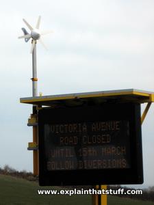
Photo: Although micro-wind turbines on homes have proved controversial, they definitely have their place. Here's the Rutland Windcharger from our top photo helping to charge the batteries in a go-anywhere, portable highway construction sign. It's getting help from the large flat solar panel mounted on top. This is a great example of how micro-wind turbines can be useful if you put them in the right place, at the right time.
Aside from the equipment, here are a few pointers worth bearing in mind:
- The best place to start is with a professional assessment of your site's wind potential, which involves a series of measurements with an anemometer. Remember that wind turbines generally work far better in open, rural areas than mounted on rooftops in cities.
- Don't assume it will automatically be windy enough to make the investment in a microturbine worthwhile: a recent UK study of microturbines by Encraft found a mixed picture, with good performance from the best-located turbines and the very worst performing model (embarrassingly) not even producing enough electricity to power its own electronics—in other words, using more electricity overall than it produced. Some contribution to the environment!
- Depending on where you live, you will almost certainly need planning consent for a wind turbine, so check that out carefully with your local authority first.
- Sound out your neighbors before you start spending any money: instead of turning your "local friends" into bitter enemies with your rooftop propeller, maybe you could persuade them to join you in a community green-energy venture?
- Remember that roof-mounted wind turbines could prove noisy and cause problems with vibration.
- Don't forget that there are all kinds of other energy technologies that might give a quicker and better return on your investment and make more difference to the planet. Energy efficiency measures (such as improved heat insulation) generally give the quickest payback for least cost and make the most difference in the short-term, and solar hot water systems work very well almost anywhere. Ground-source heat pumps are also are also worth a look .
XXX . V000 Design and implementation of a controllable model wind turbine
An experimental investigation was conducted to examine the
===== MA THE TRANSISTOR ACTIVE MATIC =====
Tidak ada komentar:
Posting Komentar