digital electronics and driving electronics controls for IDE (Integrated Drive Electronics) in The Drive for Digital Cars AMNIMARJESLOW GOVERNMENT 91220017 LOR EL DIGITAL CARS ELUSE TO CONTROL ANOTHER SYSTEM 02096010014 LJBUSAF EL CONSIDER DRIVER XAM $$$$ $ NOR LOOP
Driver circuit
In electronics, a driver is an electrical circuit or other electronic component used to control another circuit or component, such as a high-power transistor, liquid crystal display (LCD), and numerous others.
They are usually used to regulate current flowing through a circuit or to control other factors such as other components, some devices in the circuit. The term is often used, for example, for a specialized integrated circuit that controls high-power switches in switched-mode power converters. An amplifier can also be considered a driver for loudspeakers, or a voltage regulator that keeps an attached component operating within a broad range of input voltages.
Typically the driver stage(s) of a circuit requires different characteristics to other circuit stages. For example in a transistor power amplifier, typically the driver circuit requires current gain, often the ability to discharge the following transistor bases rapidly, and low output impedance to avoid or minimize distortion
The driver ADP3418 chip (bottom left), used for driving high-power field transistors in voltage converters. Above it is seen next to such a transistor (06N03LA), probably driven by that driver.
X . I Acceleration, Braking and Steering with Sophisticated Electric Drive-By-Wire Systems
Electronic Driving Controls
With the use of our sophisticated electronic driving systems, many people can assume the responsibility of driving for themselves again. MobilityWorks offers the largest selection of electronic acceleration, braking and steering control options available to match just about any type of auto, SUV or truck on the road.
All of the hi-tech equipment we offer is manufactured by the most trusted names in the mobility industry. Our certified NMEDA QAP technicians custom fit your vehicle to the equipment specified by a certified driver rehabilitation specialist (CDRS) to meet your specific driving requirements.
AEVIT 2.0®, Smart-Shift®, Econo-Series®, and Voice Interactive Controls® are registered trademarks of EMC, LLC.
Drive-by-Wire Electronic Mobility Controls
The AEVIT 2.0® Driving Control System features the latest in drive-by-wire adaptive driving controls. “Drive-by-wire” means that the movements made by the driver with a steering input device (joystick, yoke, wheel, etc.) is converted into a digital electronic signal. A touch screen display operates a variety of vehicle functions.
Electronic Shift Controls
Smart-Shift® Intelligent Electronic Shift Controls can be installed into any vehicle equipped with an automatic transmission. A simple press of one key moves the desired gear automatically to one of the selected choices.
Universal Touchpad Console
The Econo-Series® Console System is a universal touchpad designed as an intermediate control for individuals that require access to commonly used functions such as ignition, wipers, lights, cruise control and fan speeds.
Joystick Gas, Brake & Steering
AEVIT drive-by-wire systems can be utilized with a variety of different control devices. Styles include lever, joystick, and wheel orthotic options. A CDRS will prescribe a style that is specific to your physical abilities and vehicle.
Voice Interactive Controls (VCI®)
Voice Interactive Controls (VIC®) provides physically challenged drivers with access to important secondary controls while driving, such as: shifter functions; turn signals; horn; headlight dimmer; wipers; and many voice activated features.
X . II Applications of Relays in Electronic Circuits
If the relay is transistor driven, we recommend using the relay on the collector side. The voltage impressed on the relay is always full rated coil voltage, and in the OFF time, the voltage is completely zero for avoidance of trouble in use.
(Good) Collector connection
(Care) Emitter connection
(Care) Parallel connection
With this most common connection, operation is stable.
When the circumstances make the use of this connection unavoidable, if the voltage is not completely impressed on the relay, the transistor does not conduct completely and operation is uncertain.
When the power consumed by the complete circuit becomes large, consideration of the relay voltage is necessary.
2.Countermeasures for Surge Voltage of Relay Control Transistor
If the coil current is suddenly interrupted, a sudden high voltage pulse is developed in the coil. If this voltage exceeds the breakdown voltage of the transistor, the transistor will be degraded, and this will lead to damage. It is absolutely necessary to connect a diode in the circuit as a means of preventing damage from the counter emf. As suitable ratings for this diode, the current should be equivalent to the average rectified current to the coil, and the reverse blocking voltage should be about 3 times the value of the power source voltage. Connection of a diode is an excellent way to prevent voltage surges, but there will be a considerable time delay when the relay is open. If you need to reduce this time delay you can connect between the transistor's collector and emitter a Zener diode that will make the Zener voltage somewhat higher than the supply voltage.
Take care of "Area of Safe Operation (ASO)".
3.Snap Action(Characteristic of Relay With Voltage Rise and Fall of Voltage)
Unlike the characteristic when voltage is impressed slowly on the relay coil, this is the case where it is necessary to impress the rated voltage in a short time and also to drop the voltage in a short time.
Non-pulse signal
(No Good) Without snap action
Pulse signal (square wave)
(Good) Snap action
4.Schmitt Circuit (Snap Action Circuit)
(Wave rectifying circuit) When the input signal does not produce a snap action, ordinarily a Schmitt trigger circuit is used to produce safe snap action.
Characteristic Points
1.The common emitter resistor REmust have a value sufficiently small compared with the resistance of the relay coil.
2.Due to the relay coil current, the difference in the voltage at point P when T2is conducting and at point P when T1is conducting creates hysteresis in the detection capability of Schmitt circuit, and care must be taken in setting the values.
3.When there is chattering in the input signal because of waveform oscillation, an RC time constant circuit should be inserted in the stage before the Schmitt trigger circuit. (However, the response speed drops.)
5.Avoid Darlington Circuit Connections.
(High amplification) This circuit is a trap into which it is easy to fall when dealing with high circuit technology. This does not mean that it is immediately connected to the defect, but it is linked to troubles that occur after long periods of use and with many units in operation.
(No good) Darlington connection
• Due to excessive consumption of power, heat is generated. • A strong Tr1, is necessary.
(Good) Emitter connection
Tr2 conducts completely. Tr1 is sufficient for signal use.
6.Residual Coil Voltage
In switching applications where a semiconductor (transistor, UJT, etc.) is connected to the coil, a residual voltage is retained at the relay coil which may cause incomplete restoration and faulty operation. By using DC coils, there may be a reduction in; the danger of incomplete restoration, the contact pressure, and the vibration resistance. This is because the drop-out voltage is 10% or more of the rated voltage, a low value compared to that for AC coil, and also there is a tendency to increase the life by lowering the drop-out voltage. When the signal from the transistor's collector is taken and used to drive another circuit as shown in the figure on the right, a minute dark current flows to the relay even if the transistor is off. This may cause the problems described above.
Connection to the next stage through collector
2. Relay Drive by Means of SCR
1.Ordinary Drive Method
For SCR drive, it is necessary to take particular care with regard to gate sensitivity and erroneous operation due to noise.
IGT
:
There is no problem even with more than 3 times the rated current.
RGK
:
1K ohms must be connected.
RC
:
This is for prevention of ignition error due to a sudden rise in the power source or to noise. (dv/dt countermeasure)
2.Caution Points Regarding ON/OFF Control Circuits (When Used for Temperature or Similar Control Circuits)
When the relay contacts close simultaneously with an AC single phase power source, because the electrical life of the contacts suffers extreme shortening, care is necessary.
1.When the relay is turned ON and OFF using a SCR, the SCR serves as a half wave power source as it is, and there are ample cases where the SCR is easily restored.
2.In this manner the relay operation and restoration timing are easily synchronized with the power source frequency, and the timing of the load switching also is easily synchronized.
3.When the load for the temperature control is a high current load such as a heater, the switching can occur only at peak values and it can occur only at zero phase values as a phenomenon of this type of control. (Depending upon the sensitivity and response speed of the relay)
4.Accordingly, either an extremely long life or an extremely short life results with wide variation, and it is necessary to take care with the initial device quality check.
3. Relay Drive from External Contacts
Relays for PC board use have high sensitivity and high speed response characteristics, and because they respond sufficiently to chattering and bouncing, it is necessary to take care in their drive. When the frequency of use is low, with the delay in response time caused by a condenser, it is possible to absorb the chattering and bouncing. (However, it is not possible to use only a condenser. A resistor should also be used with the capacitor.)
4. LED Series and Parallel Connections
1) In series with relay
Power consumption: In common with relay (Good) Defective LED: Relay does not operate (No good) Low voltage circuit: With LED, 1.5V down (No good) No. of parts: (Good)
2) R in parallel with LED
Power consumption: In common with relay (Good) Defective LED: Relay operate (Good) Low voltage circuit: With LED, 1.5V down (No good) No. of parts: R1 (Care)
3) In parallel connection with relay
Power consumption: Current limiting resistor R2 (Care) Defective LED: Relay operate stable (Good) Low voltage circuit: (Good) No. of parts: R2 (Care)
5. Electronic Circuit Drive by Means of a Relay
1.Chatterless Electronic Circuit
Even though a chatterless characteristic is a feature of relays, this is to the fullest extent a chatterless electrical circuit, much the same as a mercury relay. To meet the requirement for such circuits as the input to a binary counter, there is an electronic chatterless method in which chattering is absolutely not permissible. Even if chattering develops on one side, either the N.O. side contacts or the N.C. side contacts, the flip flop does not reverse, and the counter circuit can be fed pulsed without a miss. (However, bouncing from the N.O. side to N.C. side must be absolutely avoided.)
Notes:
1. The A, B, and C lines should be made as short as possible. 2. It is necessary that there be no noise from the coil section induced into the contact section.
2.Triac Drive
When an electronic circuit using a direct drive from a triac, the electronic circuit will not be isolated from the power circuit, and because of this, troubles due to erroneous operation and damage can develop easily. The introduction of a relay drive is the most economical and most effective solution. (Photo coupler and pulse transformer circuits are complicated.) When a zero cross switching characteristic is necessary, a solid state relay (SSR) should be used.
6. Power Source Circuit
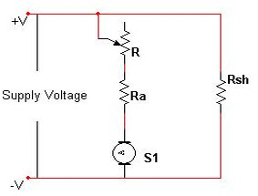
1.Constant Voltage Circuit
In general, electronic circuits are extremely vulnerable to such phenomena as power supply ripples and voltage fluctuations. Although relay power supplies are not as vulnerable as electronic circuits, please keep both ripples and the regulation within the specification. If power supply voltage fluctuations are large, please connect a stabilized circuit or constant-voltage circuit as shown in Fig. 1. If the relay power consumption is great, satisfactory results can be achieved by implementing a circuit configuration as shown in Fig. 2.
2.Prevention of Voltage Drop Due to Rush Current
In the circuit shown in Fig. 3, rush current flows from the lamp or capacitor. The instant the contacts close, the voltage drops and the relay releases or chatters. In this case it is necessary to raise the transformer's capacity or add a smoothing circuit.
Fig. 4 shows an example of the modified circuit. Fig. 5 shows a battery-powered version.
7. PC Board Design Considerations
1.Pattern Layout for Relays
Since relays affect electronic circuits by generating noise, the following points should be noted.
Keep relays away from semiconductor devices.
Design the pattern traces for shortest lengths.
Place the surge absorber (diode, etc.) near the relay coil.
Avoid routing pattern traces susceptible to noise (such as for audio signals) underneath the relay coil section.
Avoid through-holes in places which cannot be seen from the top (e.g. at the base of the relay).
Solder flowing up through such a hole may cause damage such as a broken seal.
Even for the same circuit, pattern design considerations which minimize the influence of the on/off operations of the relay coil and lamp on other electronic circuits are necessary.
(No good)
Relay coil currents and electronic circuit currents flow together through A and B.
(Good)
•Relay coil currents consist only of A1, and B1. •Electronic circuit currents consist only of A2 and B2. A simple design consideration can change the safety of the operation.
Hole and Land Diameter
The hole diameter and land are made with the hole slightly larger than the lead wire so that the component may be inserted easily. Also, when soldering, the solder will build up in an eyelet condition, increasing the mounting strength. The standard dimensions for the hole diameter and land are shown in the table below.
Standard dimensions for hole and land diameter
mm inch
Standard hole diameter
Tolerance
Land diameter
0.8 .031
±0.1 ±.039
2.0 to 3.0 .079 to .118
1.0 .039
1.2 .047
3.5 to 4.5 .138 to .177
1.6 .063
Remarks
1.The hole diameter is made 0.2 to 0.5mm .008 to .020inchlarger than the lead diameter. However, if the jet method (wave type,jet type) of soldering is used,because of the fear of solder passing through to the component side, it is more suitable to make the hole diameter equal to the lead diameter +0.2mm.
2.The land diameter should be 2 to 3 times the hole diameter.
3.Do not put more than 1 lead in one hole.
Expansion and Shrinkage of Copperclad Laminates
Because copperclad laminates have a longitudinal and lateral direction,the manner of punching fabrication and layout must be observed with care. The expansion and shrinkage in the longitudinal direction due to heat is 1/15 to 1/2 that in the lateral,and accordingly, after the punching fabrication, the distortion in the longitudinal direction will be 1/15 to 1/2 that of the lateral direction. The mechanical strength in the longitudinal direction is 10 to 15% greater than that in the lateral direction. Because of this difference between the longitudinal and lateral directions, when products having long configurations are to be fabricated, the lengthwise direction of the configuration should be made in the longitudinal direction, and PC boards having a connector section should be made with the connector along the longitudinal side.
Example : As shown is the drawing below, the 150mm 5.906 inch direction is taken as the longitudinal direction.
Also, as shown in the drawing below, when the pattern has a connector section, the direction is taken as shown by the arrow in the longitudinal direction
2.When it is Necessary to Use Hand Soldering for One Part of a Component After Dip Soldering Has Been Done
By providing a narrow slot in the circular part of the foil pattern, the slot will prevent the hole from being plugged with solder.
3.When The Printed Circuit Board Itself is Used as a Connector
1.The edge should be beveled. (This prevents peeling of the foil when the board is inserted into its socket.)
2.When only a single side is used as the connector blade, if there is distortion in the circuit board, contact will be defective. Care should be taken.
4.PC Board Reference Data
This data has been derived from samples of this company's products. Use this data as a reference when designing printed circuit boards.
Conductor Width
The allowable current for the conductor was determined from the safety aspect and the effect on the performance of the conductor due to the rise in saturation temperature when current is flowing. (The narrower the conductor width and the thinner the copper foil, the larger the temperature rise.) For example, too high a rise in temperature causes degradation of the characteristic and color changes of the laminate. In general, the allowable current of the conductor is determined so that the rise is temperature is less than 10°C. It is necessary to design the conductor width from this allowable conductor current. Fig. 1, Fig. 2, Fig. 3 show the relationship between the current and the conductor width for each rise in temperature for different copper foils. It is also necessary to give consideration to preventing abnormal currents from exceeding the destruction current of the conductor. Fig. 4 shows the relationship between the conductor width and the destruction current.
Space Between Conductors
Fig. 6 shows the relationship between the spacing between conductors and the destruction voltage. This destruction voltage is not the destruction voltage of the PCB; it is the flash over voltage (insulation breakdown voltage of the space between circuits.) Coating the surface of the conductor with an insulating resin such as a solder resist increases the flash over voltage, but because of the pin holes of the solder resist, it is necessary to consider the conductor destruction voltage without the solder resist. In fact, it is necessary to add an ample safety factor when determining the spacing between conductors. Table 1 shows an example of a design for the spacing between conductors. (Taken from the JIS C5010 standards.) However, when the product is covered by the electrical products control law, UL standards or other safety standards, it is necessary to conform to the regulations.
Example of conductor spacing design
Maximum DC and AC Voltage Between Conductors (V)
Minimum Conductor Spacing (mm inch)
0 to 50
0.381 .015
51 to 150
0.635 .025
151 to 300
1.27 .050
301 to 500
2.54 .100
500 or more
Calculated at 0.00508 mm/V
X . IIII Digital Buffer
Digital Buffers can be used to isolate other gates or circuit stages from each other preventing the impedance of one circuit from affecting the impedance of another.
In a previous tutorial we looked at the digital Not Gate commonly called an inverter, and we saw that the NOT gates output state is the complement, opposite or inverse of its input signal.
So for example, when the single input to NOT gate is “HIGH”, its output state will NOT be “HIGH”. When its input signal is “LOW” its output state will NOT be “LOW”, in other words it “inverts” its input signal, hence the name “Inverter”.
But sometimes in digital electronic circuits we need to isolate logic gates from each other or have them drive or switch higher than normal loads, such as relays, solenoids and lamps without the need for inversion. One type of single input logic gate that allows us to do just that is called the Digital Buffer.
Unlike the single input, single output inverter or NOT gate such as the TTL 7404 which inverts or complements its input signal on the output, the “Buffer” performs no inversion or decision making capabilities (like logic gates with two or more inputs) but instead produces an output which exactly matches that of its input. In other words, a digital buffer does nothing as its output state equals its input state.
Then digital buffers can be regarded as Idempotent gates applying Boole’s Idempotent Law because when an input passes through this device its value is not changed. So the digital buffer is a “non-inverting” device and will therefore give us the Boolean expression of: Q = A.
Then we can define the logical operation of a single input digital buffer as being:
“Q is true, only when A is true”
In other words, the output ( Q ) state of a buffer is only true (logic “1”) when its input A is true, otherwise its output is false (logic “0”).
Related Products: Zero Delay Buffer
The Single Input Digital Buffer
Symbol
Truth Table
The Digital Buffer
A
Q
0
0
1
1
Boolean Expression Q = A
Read as: A gives Q
The Digital Buffer can also be made by connecting together two NOT gates as shown below. The first will “invert” the input signal A and the second will “re-invert” it back to its original level performing a double inversion of the input.
Double Inversion using NOT Gates
You may be thinking “what’s the point of a Digital Buffer“? If it does not invert or alter its input signal in any way, or make any logical decisions or operations like the AND or OR gates do, then why not just use a piece of wire instead, and that’s a good point. But a non-inverting Digital Buffer does have many uses in digital electronics with one of its main advantages being that it provides digital amplification. Digital Buffers can be used to isolate other gates or circuit stages from each other preventing the impedance of one circuit from affecting the impedance of another. A digital buffer can also be used to drive high current loads such as transistor switches because their output drive capability is generally much higher than their input signal requirements. In other words buffers can be used for power amplification of a digital signal as they have what is called a high “fan-out” capability.
Digital Buffer Fan-out Example
The Fan-out parameter of a buffer (or any digital IC) is the output driving capability or output current capability of a logic gate giving greater power amplification of the input signal. It may be necessary to connect more than just one logic gate to the output of another or to switch a high current load such as an LED, then a Buffer will allow us to do just that.
Generally the output of a logic gate is usually connected to the inputs of other gates. Each input requires a certain amount of current from the gate output to change state, so that each additional gate connection adds to the load of the gate. So the fan-out is the number of parallel loads that can be driven simultaneously by one digital buffer of logic gate. Acting as a current source a buffer can have a high fan-out rating of up to 20 gates of the same logic family.
If a digital buffer has a high fan-out rating (current source) it must also have a high “fan-in” rating (current sink) as well. However, the propagation delay of the gate deteriorates rapidly as a function of fan-in so gates with a fan-in greater than 4 should be avoided.
Then there is a limit to the number of inputs and outputs than can be connected together and in applications where we need to decouple gates from each other, we can use a Tri-state Buffer or tristate output driver.
The “Tri-state Buffer”
As well as the standard Digital Buffer seen above, there is another type of digital buffer circuit whose output can be “electronically” disconnected from its output circuitry when required. This type of Buffer is known as a 3-State Buffer or more commonly a Tri-state Buffer.
A Tri-state Buffer can be thought of as an input controlled switch with an output that can be electronically turned “ON” or “OFF” by means of an external “Control” or “Enable” ( EN ) signal input. This control signal can be either a logic “0” or a logic “1” type signal resulting in the Tri-state Buffer being in one state allowing its output to operate normally producing the required output or in another state were its output is blocked or disconnected.
Then a tri-state buffer requires two inputs. One being the data input and the other being the enable or control input as shown.
Tri-state Buffer Switch Equivalent
When activated into its third state it disables or turns “OFF” its output producing an open circuit condition that is neither at a logic “High” or “Low”, but instead gives an output state of very high impedance, High-Z, or more commonly Hi-Z. Then this type of device has two logic state inputs, “0” or a “1” but can produce three different output states, “0”, “1” or ” Hi-Z ” which is why it is called a “Tri” or “3-state” device.
Note that this third state is NOT equal to a logic level “0” or “1”, but is an high impedance state in which the buffers output is electrically disconnected from the rest of the circuit. As a result, no current is drawn from the supply.
There are four different types of Tri-state Buffer, one set whose output is enabled or disabled by an “Active-HIGH” control signal producing an inverted or non-inverted output, and another set whose buffer output is controlled by an “Active-LOW” control signal producing an inverted or non-inverted output as shown below.
Active “HIGH” Tri-state Buffer
Symbol
Truth Table
Tri-state Buffer
Enable
IN
OUT
0
0
Hi-Z
0
1
Hi-Z
1
0
0
1
1
1
Read as Output = Input if Enable is equal to “1”
An Active-highTri-state Buffer such as the 74LS241 octal buffer, is activated when a logic level “1” is applied to its “enable” control line and the data passes through from its input to its output. When the enable control line is at logic level “0”, the buffer output is disabled and a high impedance condition, Hi-Z is present on the output.
An active-high tri-state buffer can also have an inverting output as well as its high impedance state creating an active-high tri-state inverting buffer as shown.
Active “HIGH” Inverting Tri-state Buffer
Symbol
Truth Table
Inverting Tri-state Buffer
Enable
IN
OUT
0
0
Hi-Z
0
1
Hi-Z
1
0
1
1
1
0
Read as Output = Inverted Input if Enable equals “1”
The output of an active-high inverting tri-state buffer, such as the 74LS240 octal buffer, is activated when a logic level “1” is applied to its “enable” control line. The data at the input is passes through to the output but is inverted producing a complement of the input. When the enable line is LOW at logic level “0”, the buffer output is disabled and at a high impedance condition, Hi-Z.
The same two tri-state buffers can also be implemented with an active-low enable input as shown.
Active “LOW” Tri-state Buffer
Symbol
Truth Table
Tri-state Buffer
Enable
IN
OUT
0
0
0
0
1
1
1
0
Hi-Z
1
1
Hi-Z
Read as Output = Input if Enable is NOT equal to “1”
An Active-lowTri-state Buffer is the opposite to the above, and is activated when a logic level “0” is applied to its “enable” control line. The data passes through from its input to its output. When the enable control line is at logic level “1”, the buffer output is disabled and a high impedance condition, Hi-Z is present on the output.
Active “LOW” Inverting Tri-state Buffer
Symbol
Truth Table
Inverting Tri-state Buffer
Enable
IN
OUT
0
0
1
0
1
0
1
0
Hi-Z
1
1
Hi-Z
Read as Output = Inverted Input if Enable is NOT equal to “1”
An Active-low Inverting Tri-state Buffer is the opposite to the above as its output is enabled or disabled when a logic level “0” is applied to its “enable” control line. When a buffer is enabled by a logic “0”, the output is the complement of its input. When the enable control line is at logic level “1”, the buffer output is disabled and a high impedance condition, Hi-Z is present on the output.
Tri-state Buffer Control
We have seen above that a buffer can provide voltage or current amplification within a digital circuit and it can also be used to invert the input signal. We have also seen that digital buffers are available in the tri-state form that allows the output to be effectively switched-off producing a high impedance state (Hi-Z) equivalent to an open circuit.
The Tri-state Buffer is used in many electronic and microprocessor circuits as they allow multiple logic devices to be connected to the same wire or bus without damage or loss of data. For example, suppose we have a data line or data bus with some memory, peripherals, I/O or a CPU connected to it. Each of these devices is capable of sending or receiving data to each other onto this single data bus at the same time creating what is called a contention.
Contention occurs when multiple devices are connected together because some want to drive their output high and some low. If these devices start to send or receive data at the same time a short circuit may occur when one device outputs to the bus a logic “1”, the supply voltage, while another is set at logic level “0” or ground, resulting in a short circuit condition and possibly damage to the devices as well as loss of data.
Digital information is sent over these data buses or data highways either serially, one bit at a time, or it may be up to eight (or more) wires together in a parallel form such as in a microprocessor data bus allowing multiple tri-state buffers to be connected to the same data highway without damage or loss of data as shown.
Tri-state Buffer Data Bus Control
Then, the Tri-state Buffer can be used to isolate devices and circuits from the data bus and one another. If the outputs of several Tri-state Buffers are electrically connected together Decoders are used to allow only one set of Tri-state Buffers to be active at any one time while the other devices are in their high impedance state. An example of Tri-state Buffers connected to a 4-wire data bus is shown below.
Tri-state Buffer Control
This basic example shows how a binary decoder can be used to control a number of tri-state buffers either individually or together in data sets. The decoder selects the appropriate output that corresponds to its binary input allowing only one set of data to pass either a logic “1” or logic “0” output state onto the bus. At this time all the other tri-state outputs connected to the same bus lines are disabled by being placed in their high impedance Hi-Z state.
Then data from data set “A” can only be transferred to the common bus when an active HIGH signal is applied to the tri-state buffers via the Enable line, ENA. At all other times it represents a high impedance condition effectively being isolated from the data bus.
Likewise, data set “B” only passes data to the bus when an enable signal is applied via ENB. A good example of tri-state buffers connected together to control data sets is the TTL 74244 Octal Buffer.
It is also possible to connect Tri-state Buffers “back-to-back” to produce what is called a Bi-directional Buffer circuit with one “active-high buffer” connected in parallel but in reverse with one “active-low buffer”.
Here, the “enable” control input acts more like a directional control signal causing the data to be both read “from” and transmitted “to” the same data bus wire. In this type of application a tri-state buffer with bi-directional switching capability such as the TTL 74245 can be used.
We have seen that a Tri-state buffer is a non-inverting device which gives an output (which is same as its input) only when the input to the Enable, ( EN ) pin is HIGH otherwise the output of the buffer goes into its high impedance, ( Hi-Z ) state. Tri-state outputs are used in many integrated circuits and digital systems and not just in digital tristate buffers.
Both digital buffers and tri-state buffers can be used to provide voltage or current amplification driving much high loads such as relays, lamps or power transistors than with conventional logic gates. But a buffer can also be used to provide electrical isolation between two or more circuits.
We have seen that a data bus can be created if several tristate devices are connected together and as long as only one is selected at any one time, there is no problem. Tri-state buses allow several digital devices to input and output data on the same data bus by using I/O signals and address decoding. Tri-state Buffers are available in integrated form as quad, hex or octal buffer/drivers in both uni-directional and bi-directional forms, with the more common being the TTL 74240, the TTL 74244 and the TTL 74245 as shown.
Commonly available Digital Buffer and Tri-state Buffer IC’s include:
TTL Logic Digital Buffers
74LS07 Hex Non-inverting Buffer
74LS17 Hex Buffer/Driver
74LS244 Octal Buffer/Line Driver
74LS245 Octal Bi-directional Buffer
CMOS Logic Digital Buffers
CD4050 Hex Non-inverting Buffer
CD4503 Hex Tri-state Buffer
HEF40244 Tri-state Octal Buffer
74LS07 Digital Buffer
74LS244 Octal Tri-state Buffer
X . IIIII Digital Logic Gates Summary
Digital Logic Gates, we have seen that there are three main basic types of digital logic gate, the AND Gate, the OR Gate and the NOT Gate.
We have also seen that each gate has an opposite or complementary form of itself in the form of the NAND Gate, the NOR Gate and the Buffer respectively, and that any of these individual gates can be connected together to form more complex Combinational Logic circuits.
We have also seen, that in digital electronics both the NAND gate and the NOR gate can both be classed as “Universal” gates as they can be used to construct any other gate type. In fact, any combinational circuit can be constructed using only two or three input NAND or NOR gates. We also saw that NOT gates and Buffers are single input devices that can also have a Tri-state High-impedance output which can be used to control the flow of data onto a common data bus wire. Digital Logic Gates can be made from discrete components such as Resistors, Transistors and Diodes to form RTL (resistor-transistor logic) or DTL (diode-transistor logic) circuits, but today’s modern digital 74xxx series integrated circuits are manufactured using TTL (transistor-transistor logic) based on NPN bipolar transistor technology or the much faster and low power CMOS based MOSFET transistor logic used in the 74Cxxx, 74HCxxx, 74ACxxx and the 4000 series logic chips.
The eight most “standard” individual Digital Logic Gates are summarised below along with their corresponding truth tables.
Standard Logic Gates
The Logic AND Gate
Symbol
Truth Table
2-input AND Digital Logic Gate
B
A
Q
0
0
0
0
1
0
1
0
0
1
1
1
Boolean Expression Q = A.B
Read as A AND B gives Q
The Logic OR Gate
Symbol
Truth Table
B
A
Q
0
0
0
0
1
1
1
0
1
1
1
1
Boolean Expression Q = A + B
Read as A OR B gives Q
Inverting Logic Gates
The Logic NAND Gate
Symbol
Truth Table
B
A
Q
0
0
1
0
1
1
1
0
1
1
1
0
Boolean Expression Q = A . B
Read as A AND B gives NOT Q
The Logic NOR Gate
Symbol
Truth Table
B
A
Q
0
0
1
0
1
0
1
0
0
1
1
0
Boolean Expression Q = A + B
Read as A OR B gives NOT Q
Exclusive Logic Gates
The Logic Exclusive-OR Gate (Ex-OR)
Symbol
Truth Table
B
A
Q
0
0
0
0
1
1
1
0
1
1
1
0
Boolean Expression Q = A B
Read as A OR B but not BOTH gives Q (odd)
The Logic Exclusive-NOR Gate (Ex-NOR)
Symbol
Truth Table
B
A
Q
0
0
1
0
1
0
1
0
0
1
1
1
Boolean Expression Q = A B
Read if A AND B the SAME gives Q (even)
Single Input Logic Gates
The Hex Buffer
Symbol
Truth Table
A
Q
0
0
1
1
Boolean Expression Q = A
Read as A gives Q
The NOT gate (Inverter)
Symbol
Truth Table
A
Q
0
1
1
0
Boolean Expression Q = not A or A
Read as inverse of A gives Q
The operation of the above Digital Logic Gates and their Boolean expressions can be summarised into a single truth table as shown below. This truth table shows the relationship between each output of the main digital logic gates for each possible input combination.
Digital Logic Gate Truth Table Summary
The following logic gates truth table compares the logical functions of the 2-input logic gates detailed above.
Inputs
Truth Table Outputs For Each Gate
B
A
AND
NAND
OR
NOR
EX-OR
EX-NOR
0
0
0
1
0
1
0
1
0
1
0
1
1
0
1
0
1
0
0
1
1
0
1
0
1
1
1
0
1
0
0
1
Truth Table Output for Single-input Gates
A
NOT
Buffer
0
1
0
1
0
1
Pull-up and Pull-down Resistors
One final point to remember, when connecting together digital logic gates to produce logic circuits, any “unused” inputs to the gates must be connected directly to either a logic level “1” or a logic level “0” by means of a suitable “Pull-up” or “Pull-down” resistor ( for example 1kΩ resistor ) to produce a fixed logic signal. This will prevent the unused input to the gate from “floating” about and producing false switching of the gate and circuit.
As well as using pull-up or pull-down resistors to prevent unused logic gates from floating about, spare inputs to gates and latches can also be connected together or connected to left-over or spare gates within a single IC package as shown.
X . IIIIII EMC Handicap Driving Controls
Electronic Mobility Controls manufacturers unique and necessary digital mobility driving devices for drivers who are disabled. EMC enables greater independence through their electric disabled driving devices. Whether you seek primary control options or secondary control options, EMC answers the call. Access Options in Watsonville and Sunnyvale is the best source for EMC disabled equipment in California.
EMC-L-Series Orthotics
EMC-W-Series Orthotic
EMC-J-Series Orthotic
EMC WL-Series
Gas, Brake, and Steering System
The WL-Series is a Gas, Brake & Steering system that utilizes the same wheel input device as the W-Series for Steering and the same lever input device as the L-Series for Gas & Brake. These input devices are designed to be mounted on each side of the driver. However, they are interchangeable so that the system can be tailored for right or left hand steering.
EMC XL-Series
Gas, Brake, and Steering System
The XL-Series is a Gas, Brake & Steering system that utilizes two separate control inputs. A joystick constrained to the X-axis (same as the X-Series) is used as the Steering input and a lever input device (same as the L-Series) is used for operation of the Gas & Brake.
EMC XY-Series
Gas, Brake, and Steering System
The XY-Series is a Gas, Brake & Steering system that utilizes two separate control inputs. A joystick input device constrained to motion in the X-axis is used for Steering (same as the X-Series) and a separate joystick input device constrained to motion in the Y-axis is for Gas & Brake (same as the Y-Series). This system is well suited for persons requiring joystick control but able to utilize dual input devices.
EMC WY-Series
Gas, Brake, and Steering System
The WY-Series is a Gas, Brake & Steering system that utilizes two separate control inputs. A wheel input device is provided for Steering (same as the W-Series) and a Y-axis joystick for Gas & Brake (same as the Y-Series). This system is well suited for persons requiring extremely low-effort Gas & Brake control and a miniature low-effort steering wheel.
EMC J-Series
Gas, Brake, and Steering System
The J-Series input device is a Gas, Brake & Steering system that utilizes a multi-axis joystick input device. Motion in the X-axis is for Steering and the Y-axis motion is for Gas & Brake. The exposed height of the joystick is approximately 4.25" and an angular displacement, or range, of only 50 degrees is required to move the input from the full left steer position to full right steer or from the full gas position to full brake. As with all AEVIT
EMC SmartShift
Electronic Shift Control
Smart-Shift sets the industry standard for "Electronic Shift" applications, and can be installed into any vehicle equipped with an automatic transmission. No more missed gears or waiting in traffic for other actuator systems to slowly move. Smart-Shift travels from Park to Drive in 1.3 seconds! Simply press the desired key one time and the actuator moves to the desired gear automatically.
There are 2-styles for Smart-Shift
Smart-Shift incorporates positional feedback as well as fully automatic positioning of the actuator in any of the five gear selector choices, i.e., Park, Reverse, Neutral, Drive and Drive 2. When a key is depressed, the actuator will move the transmission to the selected gear, stop automatically, and illuminate the LED indicator.
EMC Econo Series
Econo Series Console System
The Econo-Series Touchpad is offered as an alternative to drivers not requiring Primary Controls for gas/brake and steering. It is designed as an "intermediate" console system to meet the needs of individuals who require touchpad access to only the most commonly-used vehicle functions. Because of its universal design, it also has the flexibility to operate in nearly any make or model vehicle.
Econo-Series is the simplest and most economic solution for those individuals who require remote access to more functions than can be provided with our 2-Function touchpad products.
The contoured Econo-Series keypad (6"H x 4-1/2"W x 1"D) offers access to fifteen vehicle functions with only eight multi-function buttons. Each button is color-coded and represented by universal icons and lighted LEDs so that a person can take full advantage of his/her visual perception for quick, at-a-glance operation. Also, these raised tactile buttons are sufficiently spaced to prevent inadvertent activation by individuals lacking finger dexterity.
X . IIIIIII Design, Prototype, and Deploy Digital Control Systems for Power Electronics Applications
This application note discusses a new design approach for the development of digital control systems for switching power electronics circuits. By taking advantage of the co-simulation capabilities between NI Multisim and NI LabVIEW, and the common National Instruments Reconfigurable I/O (NI RIO) architecture, designers can increase their productivity and reduce cost and time to market.
Digital controllers offer many advantages for power electronics applications where high efficiency, flexibility and size are important. Engineers have been using microprocessors and DSPs for the development of these control systems, however the complexity of these designs is high and prototypes are expensive. Furthermore, many design iterations are needed to test and validate these systems because there is a disconnect in the development tools, which results in higher costs and increased time to market.
For instance, a typical DC motor control application requires the development of a power stage circuitry (analog design) to drive the DC motor, and a control algorithm (digital design). Traditionally both stages are developed and simulated separately which results in errors that can be propagated to the prototype stage.
National Instruments offers a new design approach for power electronics applications. Designers can now simulate and optimize an entire system using system co-simulation. NI Multisim, a SPICE-based circuit design and simulation tool, is used to model and analyze the power stage; NI LabVIEW, a graphical programming environment, is used to design the digital controller. Then, the entire system is simulated and optimized using multi-domain co-simulation. Moreover, the code developed in the simulation stage can be compiled to physical hardware with minor modifications.
In this application note, we design, prototype and deploy a digital speed controller for a brushed DC motor to illustrate the advantages of this new design approach for power electronics.
2. Application Requirements
The application requirements for the design are:
Use a brushed DC motor with quadrature encoder.
Run the motor using a 12 V supply.
Spin an inertial load (0.001 kg ∙ m2) periodically at 1200 RPM for 3 seconds and at -1200 RPM for 3 seconds.
Speed overshoot must not exceed 1400 RPM.
Motor must reach the final speed in under a second.
Use 20 kHz for the PWM switching frequency.
3. Design: Analog Power Stage & Digital Controller
Analog Power Stage
The analog power stage of the design provides the interface to connect and control the DC motor. Since one of the key application requirements for the design is that the motor must spin in both directions, the design can be built around a common H-bridge topology (Figure 1).
Figure 1. H-bridge topology
The DC motor will be powered by a 12 V power supply that must be able to accelerate the motor to the required speed within the required amount of time (< 1s). Circuit simulation in Multisim can help the designer determine whether the available power supply meets this requirement. The circuit shown in Figure 2 was built and simulated in Multisim using one of the brushed DC machine SPICE models included in the Master Database. This model can be customized using the nominal motor parameters from the manufacturer’s datasheet.
Figure 2. Circuit used to measure theoretical speed and current response
Simulation results in Multisim (Figure 3) indicate that the motor is capable of reversing from -1200 RPM to +1200 RPM in 0.51 s, however the motor experiences a large inrush current of approximately 18 A when driven hard in the opposite direction. This can be resolved by applying voltage to the armature more gradually. After extensive simulation it is determined that by applying the 12 V supply with a slew rate limit of 34 V/s, the peak inrush current can be reduced to 13.5 A. With this approach it takes 0.7 s (instead of 0.51 s) to reach the desired speed, which is still within the design requirement.
Figure 3. Theoretical speed and current responses
The switch selection for the H-bridge topology is based on the operating voltage and the maximum expected armature currents. This design features 58A N-channel MOSFETs for the low-side switch and 80A P-channel MOSFETs for the high-side. Also, a gate driver is selected for all the switches. Multisim simulation can also be used to model worst case switching losses.
In preparation for the next step (digital controller design) you need to build a plant model to design and test the controller using co-simulation with Multisim and LabVIEW. In Figure 4 you can see the plant model in Multisim. Gate drivers are not considered in the plant model because their effect on the system dynamics is minimal.
Figure 4. Plant model in Multisim for co-simulation
Digital Controller Design
The digital controller is implemented in LabVIEW and consists of the following design blocks: speed decoder, PI controller, PWM Generator and H-bridge driver. Figure 5 shows a block diagram of the digital controller. All these blocks are implemented in LabVIEW, except the DC Motor (plant model). Table 1 provides details about the components of the digital controller.
Figure 5. Digital controller diagram
Table 1. Elements of the digital controller
Design Block
Description
Speed decoder
Calculates position, velocity and acceleration based on a quadrature encoder signal from the motor.
PI controller
Discretized PI controller designed to operate at a rate of 40 MHz (default clock speed for most FPGAs).
PWM generator
A PWM duty cycle of 50-100% spins the motor in the clockwise (positive) direction, while a 0-50% PWM duty cycle spins the motor in the counter-clockwise (negative) direction.
H-bridge driver
Converts the PWM duty cycle into the drive signals for the H-bridge switches.
System Co-simulation
Now that the analog power stage and the digital controller design have been completed, the entire system can be analyzed and optimized using Multisim-LabVIEW co-simulation without the need of building a physical prototype. This reduces design iterations because errors can be detected and fixed early in the design flow. Furthermore, the LabVIEW code created for the system simulation can be reused and implemented in hardware with minimal changes.
In the co-simulation environment, the Multisim and LabVIEW simulation engines concurrently perform a non linear time-domain analysis, exchanging data at the end of each time-step. This means the simulation results are accurate because all the system dynamics is taken into consideration.
The LabVIEW block diagram for the system simulation is shown in Figure 6.
Figure 6. Closed loop system simulation in LabVIEW
From the previous figure you can see that nodes 1-4 are elements of the digital controller:
Speed decoder
PI controller
PWM generator
H-bridge driver
The plant model, represented by node 5, consists of the MOSFET switches, brushed DC motor, and an optical encoder executing in the Multisim simulation environment.
Figure 7 features a 1 s simulation of the system setting the motor speed from stopping to 1200 RPM. In the graph, the setting speed is represented by the red trace. The yellow trace depicts the simulated sensed speed. These results show that the design meets the application requirements.
Figure 7. Co-simulation results
With Multisim and LabVIEW co-simulation designers can also evaluate current peaks and control signals, assess the efficiency of speed encoding/decoding and predict the transient time response of the motor speed build-up.
4. Prototype: NI CompactRIO
After evaluating the system co-simulation results and fine tuning the digital controller, designers have confidence to develop a physical prototype. An FPGA-based platform like NI CompactRIO can be used to deploy the code of the digital controller and the analog stage can be built on a protoboard. The NI cRIO-9074 controller features a Xilinx Spartan-2 2M FPGA and a 400 Mhz real-time processor, 8 slots for I/O modules and communication ports. In this stage there is no need to create new LabVIEW code to program the digital controller in the CompactRIO controller, we can simply reuse (with minor modifications) the same code developed for the system co-simulation. In Figure 8 we can see that nodes 1-4 are the same nodes that were used for Multisim and LabVIEW co-simulation.
Figure 8. FPGA implementation of the motor controller
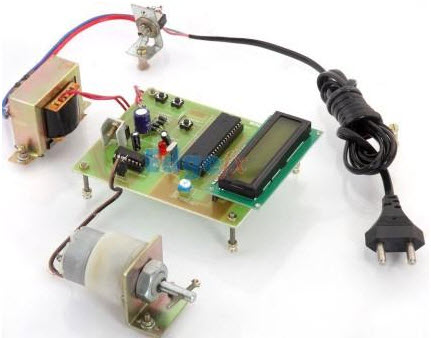
The analog power stage (H-bridge and gate drivers) is prototyped on a basic protoboard using discrete components. NI CompactRIO I/O modules are used to sample the armature current and interface with the velocity encoder and the gate drivers. Figure 9 shows a photograph of the first physical prototype.
Figure 9. DC motor controller prototype
In order to have a more solid prototype for testing purposes, designers can build a Printed Circuit Board (PCB) of the analog circuitry using Multisim and Ultiboard. One of the advantages of Multisim for quick prototyping is its database of connector symbols and footprints for NI hardware (for instance: CompactRIO, Single-Board RIO), which saves time and reduces errors. In addition, Multisim includes industry standard connectors from leading manufacturers.
Once the Multisim schematic is transferred to Ultiboard, designers can take advantage of a flexible and friendly environment optimized for rapid PCB design. In Figure 10 you can see the PCB design of the analog circuitry for the DC motor controller. This is a four-layer board with a current rating of 20 A. Ultiboard can generate all the standard files (Geber, DXF, NC Drill) needed to fabricate the PCB.
Figure 10. PCB design in Ultiboard
Figure 11. DC motor controller prototype with PCB created in Multisim and Ultiboard
5. Deploy: NI Single-Board RIO
For high-volume and OEM applications designers can take advantage of the NI Single-Board RIO embedded products. These embedded devices offer the same hardware architecture as NI CompactRIO in a board-level reconfigurable system.
The digital controller for the DC motor can be easily implemented on a NI Single-Board RIO device with minor modifications to the design. The NI sbRIO-9606 (Figure 12) offers the smallest form factor of the Single-Board RIO family. This device features a RIO Mezzanine Card (RMC) connector, which is a high-speed connector that provides direct access to the processor and 96 3.3 V digital I/O FPGA lines. With Multisim and Ultiboard designers can create custom boards (or RIO Mezzanine Cards) to take more advantage of the platform.
Figure 12. Back view of the sbRIO-9606 featuring a RMC connector
For the DC motor controller design the digital stage can be deployed to the sbRIO-9606 with minor changes to the LabVIEW code. These modifications are needed to ensure you use the appropriate I/O in the Single-Board RIO device. On the other hand, a RIO Mezzanine Card containing the analog circuitry can be designed with Multisim and Ultiboard; Figure 13 shows a photograph of the final design.
Figure 13. DC motor controller deployment
The custom board features push buttons that the user can use to set/change the desired speed and an LCD screen that displays the current speed and direction of the motor controller. The digital controller is running in the sbRIO-9606, which is attached to the custom board (Figure 14).
Figure 14. Secondary side of the custom board with the sbRIO-9606 attached
6. Conclusion
In this application note we discussed a new design approach for power electronics applications with Multisim, LabVIEW and the NI RIO platform. By using system co-simulation and the common hardware architecture offered by NI RIO devices, designers can quickly develop and optimize digital control systems for switching power electronics circuits.
X . IIIIIII High Tech Driving
High Tech Driving
The Future of Driving – Now
AVM is a certified dealer for EMC (Electronic Mobility Controls), the standard in “Drive-by-Wire” driving controls. “Drive-by-Wire” means that the movements made by the driver with the steering Input Device (joystick, yoke, wheel) is not transmitted mechanically, but instead, is sensed and converted into a digital electronic signal that is transmitted to intelligent Drive Modules that, in turn, command intelligent Electromechanical Servos to steer the front wheels. The same method of control is applied to the braking and acceleration of the vehicle.
The new AEVIT 2.0 Driving Control System features the latest technological advancements. Electronic display for controlling:
Ignition
Starting
Lights
Turn Signals/Hazards
Horn/Dimmer
Wipers/Auto Wipers
Cruise On/Set
Shift (P,R,N,D,D2)
Windows
Locks
Electric Park Brake
Left and Right Power Mirror Control
Front and Rear Fans
Vent Selection
Temperature
Other Programmable Functions
Additional Control Accessories Include:
Voice Interactive Controls providing “voice activation” of up to 18 secondary controls and communicates instructions to the driver on the status/operation of AEVIT primary driving controls. The Bluetooth Option allows the driver to use a Bluetooth headset and receiver in conjunction with the Voice Interactive Controls
Remote Start for starting the vehicle from up to 240 feet away.
For those who require high tech driving solutions, AVM has the training and experience to provide the answer you need. We work with rehab specialists and engineers from Vocational Rehabilitation, the Veterans Administration and others to provide the total mobility solution now.
X . IIIIIIII Driving LEDs — Choosing Between Analog and Digital Topologies
The choice between analog or digital drivers depends on the application requirements. Whichever route you choose, you've just passed the first of many decision points. No longer relegated to simple indicator lights on consoles or Christmas decorations, LEDs are completely transforming the lighting industry. Their high efficiency, low implementation cost, and long operating life continue to supplant existing lighting technologies. In addition, the silicon and design tools available for LED development make it possible to take advantage of these devices in applications across every industry.
The challenge for engineers new to this technology is that LEDs are driven by analog systems that can be quite complex. Systems can be based on current or voltage, and advanced compensation is required to maintain consistency and efficiency across loads, color changes, and string lengths. Further complicating design is the fact that LEDs from different manufacturing runs can vary significantly enough to require calibration for some applications.
There are also many approaches for implementing LED technology, varying from very simple analog driver circuitry for light bulb replacement, to advanced digital MCU-based systems for stage or street lighting, requiring adaptive compensation and remote control through a wired or wireless communications link. Which implementation is optimal, however, depends upon many factors. This article will look at some of the more important elements of an LED-based design and their impact on cost, power efficiency, and design simplicity.
Analog versus digital
A basic LED system takes an AC or DC input and converts it to an appropriate DC voltage or current to drive the LED (see Figure 1). One of the most common applications utilizing a pure analog topology is light bulb replacement, where the LED system needs to be as simple as the product it is replacing. For such an application, advanced features such as a communications link or internal intelligence are unnecessary, making an analog approach ideal.
Within a digital system (see Figure 2), each LED string is driven by an MCU using pulse width modulation (PWM). If the MCU can source enough power, it can drive LEDs directly. For systems driving high brightness LEDS, or strings of LEDs, the PWM drives a MOSFET that performs the actual power switching.
Figure 1: An analog implementation of an LED system. (Source: Texas Instruments. Used with permission.)
One issue developers may face is a lack of familiarity with LED technology. For example, fixture manufacturers moving from incandescent to solid state lighting do not necessarily have much experience with electronics in general. The prospect of struggling to work out digital power conversion algorithms and power supply design, especially without in-house power expertise, makes a simple analog approach appealing.
Figure 2: A digital implementation of an LED system. (Source: Texas Instruments. Used with permission.)
Another advantage of analog systems is the ability to integrate the higher voltage components. For example, it is possible to reduce the overall number of MOSFETs required in a system compared to a digital implementation. Simple feedback is also less complex with an analog-based approach. A digital system requires an ADC to measure current or voltage to be used in a software-based compensation algorithm. For an analog system, the feedback loop consists of an error amplifier that adjusts the operating voltage across the LED to match an internal voltage reference.
However, while the simplest approach is often the more robust from an engineering perspective, it is not always the most attractive to the marketplace, or the most cost-effective. A digital approach to driving LEDs provides a more flexible topology compared to analog systems. For example, a PWM configured through software can reliably drive a wide range of voltages and currents. This is especially useful for applications that may need to support a variety of LED types to match the brightness requirement of each customer. Reconfiguring the PWM and compensation loop, for example, allows developers to replace a 350 mA string with a 700 mA string without having to change the base system design. If the system has a communications link and supports remote upgrading, string replacement can take place in systems already deployed in the field.
The primary advantage of taking a digital approach is that an MCU can perform much more than just the power management function of driving LEDs. Advanced features such as power factor correction (PFC), temperature sensing, and communications tend to be significantly more cost-effective and easier to implement compared to an analog approach. The more of these features a system requires, the more likely a digital approach will be the best option. In addition, once the shift to an MCU is made, all of the other advanced digital features become available, allowing better differentiation from competitive products.
Color accuracy: Certain lighting applications, such as stage lighting, require accurate color mixing. Note that color accuracy also applies to white LEDs when the ability to maintain a specific or consistent shade/intensity is required. Compensation is required for fixed offsets (e.g., LEDs from different manufacturing bins may perform differently and will need to be calibrated) and for dynamic changes (e.g., color shifts that occur with varying temperature).
Color mixing: Some applications need the ability to blend LEDs to create varying shades of color, such as a light that washes a wall with a shifting rainbow of colors. Dynamic coordination and color accuracy between LEDs can potentially become important factors.
Dimming: Triac dimming can be difficult to implement with analog components. In contrast, an MCU can detect the leading and trailing edge of dimmers to greatly simplify design.
Multiple strings: As the length and number of strings increases, the overall power requirements of the system increase. With an analog approach, each pair of strings requires a transformer, as well as individual rectifiers (see Figure 3). As the number of strings increases, so does the component count. At some point, it becomes advantageous to shift to a digital topology, given the fewer number of components required.
Sensors: An LED application may need to sense its environment for a number of reasons. Measuring the temperature around an LED, for example, allows for advanced color correction. A motion sensor enables intelligent control. An ambient light sensor allows the system to turn itself off when there is no need for it to be on. In each of these cases, an MCU is required to monitor the sensor, process the data, and decide how to act.
Figure 3: With an analog approach, each pair of strings requires a transformer, as well as individual rectifiers. (Source: Texas Instruments. Used with permission.)
Many systems will require an MCU to handle system management tasks, sensing, and perhaps a communications interface. The key question to ask is whether the MCU can also efficiently support drive functionality. Implementing digital LED control may be as simple as specifying a higher performance device within the same MCU family. It is also worth confirming that the MCU roadmap has devices with enough performance to introduce advanced LED functionality in next-generation designs.
If, however, the MCU is a low-end device being used solely for simple system housekeeping, it likely won't have the real-time performance to drive LEDs. In such a case, a completely different MCU family may be required to handle driving the LEDs. To reduce cost in this system, the functionality handled by the low-end MCU will then need to be migrated to the higher performance MCU, effectively requiring a complete redesign of the system. Developers may find it to be more cost-effective — and faster to market — to implement the LED subsystem separately from the system MCU, using an analog-based topology.
Efficiency
Analog LED systems are typically tuned to provide optimal efficiency at a specific load. When engineers begin to design an LED system using an analog approach, they have the freedom to choose what this load will be. For the highest efficiency, the load selected should be the load at which the system will operate the majority of the time. For lights, this is often the highest brightness. One disadvantage of this approach is that when the light operates at a different load, such as when the light is dimmed, efficiency diminishes as well. Another disadvantage is that if an application needs a configuration of strings with a different number of LEDs, the optimal load value changes as well, requiring a redesign of the analog circuitry. With a digital approach, a more complex driving algorithm can be used to dynamically adjust the drive power to the current load. This allows the system to operate optimally — not just at the optimal load, but across the entire operating load range.
Some efficiency techniques are possible with an MCU that are generally not available in analog component form. An example of such a technology is buck PFC. For a variety of reasons, power for a traditional industrial lighting application goes through a two-stage conversion process. First, the 120 VAC input is boosted to 400 VDC or higher. Since LED strings operate at a lower voltage, such as 40 V, the voltage then needs to be bucked down.
Unfortunately, raising and lowering the voltage results in unnecessary losses and therefore reduced efficiency. Today's MCUs can bypass these inefficiencies through buck PFC techniques that convert the input AC voltage directly to the required DC voltage. Not only does this eliminate the DC/DC conversion stage, it yields higher efficiency and uses smaller capacitors.
Power factor correction
PFC is an advanced technology that is being required in more and more applications. Power, by nature, is resistive. The circuitry to drive LEDs utilizes elements such as inductors and capacitors that change the profile of power supplied to the circuit. Effectively, the transmission line has to be sized for a larger current than is actually being used within the circuit. PFC makes LEDs and their circuitry appear like a resistor, similar to how incandescent lights appear to the transmission line, thus reducing the impact on transmission line size.
Useable power is something that the utility companies care very much about. For example, if equipment with a PFC of 1.0 is connected, 100 percent of the plant's power is available for use. With a PFC of 0.5, however, only half of the plant's power is available as useable power. In other terms, without PFC technology implemented in electronic devices, utility companies will have to build bigger plants to provide sufficient useable power.
Whether a system needs PFC or not can be a hard question to answer because PFC doesn't necessarily bring direct benefits to users of LED-based equipment. This can make it difficult to justify the expense of adding PFC. To aid in its adoption, many countries are mandating the use of PFC. In the US, low wattage residential lighting does not have PFC requirements. For commercial lighting, PFC is generally required.
Communications
Depending upon the application, developers may find it useful to integrate a communications link into an LED-based lighting system. The link can be wired or wireless, and serves as the foundation for intelligent and remote control of the system. Note that to support a communications link, the system will need an MCU to transmit/receive data and act upon it. This MCU may or may not be used to drive the LEDs as well.
For equipment such as industrial lights or home automation lighting that are plugged into an outlet, powerline communications (PLC) technology provides a robust link leveraging the existing power infrastructure of the home or factory building. For a connection that is suitable for portable devices that run off of a battery or cannot support PLC, a wireless technology like ZigBee can provide a cost- and power-effective implementation. If the LED system is part of a larger system that already has a network connection which can be leveraged, communication can take over an interprocessor interface such as I2C or SPI. A system could also have a manual communications link like USB. In such a case, the system could store performance data for periodic manual downloading by a technician performing scheduled maintenance.
Certain applications may also need to support a protocol layer. For example, DALI and DMX512 enable developers to build lighting equipment that is compatible with existing control systems. Other systems may collect performance statistics that are useful for a variety of reasons. For example, a system could store statistics on each string of lights it controls. When a light burns out, the system then triggers a maintenance alert. A more advanced system could track the operating temperature of each light and how long it has been lit to predict when the light will fail, so that preemptive maintenance can be performed.
Self-monitoring capabilities are becoming increasingly important for a wide range of commercial and industrial applications. For example, cities pay a set fee to operate street lights, regardless of how much power the lights actually consume. If each street light has its own meter, the city can pay based on measured usage, resulting in substantial operating savings. Over time, these savings would more than offset the added cost of the communications link and management infrastructure.
Choices
Whether you decide to go analog or digital, you'll have a myriad of component choices. In the past, each LED string had its own controller. Today, analog LED drivers and digital controllers provide a more cost-effective approach through their ability to drive multiple strings with a single controller.
The variety of analog LED drivers is quite extensive, offering a range of capabilities depending upon the application. For example, the TLC5960 LED driver from Texas Instruments can drive up to eight channels and uses intelligent headroom voltage control to optimize the forward voltage of each string, thereby allowing developers to accommodate the subtle differences between LED strings due to binning. The TLC5960 also has inputs to measure the current/voltage through each string and provide feedback to dynamically adjust the output of the DC/DC converter to maintain a constant current through strings.
For digital designs, TI offers the TMS320F2806x for advanced LED applications. The MCU is part of the company's Piccolo family and offers integrated floating point processing to support features such as PFC and PLC.
Cypress Semiconductor provides a hybrid approach to LED design with its PSoC family of microcontrollers. Reprogrammable analog and digital blocks within the PSoC architecture allow developers to implement drive functionality in hardware to maximize performance and resolution.
Developers also have access to evaluation kits to accelerate product design and development. Development kits provide engineers new to LED technology with a fast way to evaluate topologies and components. The Piccolo Multi-DC-DC Color LED Kit from TI, for example, introduces developers to designing with color LEDs (see Figure 4). Alternatively, TI's UCC28810-EVM003 drives multiple LED strings and shows developers how to efficiently scale the magnetics of a design. Rather than having multiple DC/DC converters that need to be regulated individually to achieve consistent lighting, the kit uses transformers with secondary windings to reduce component count. In addition, developers new to LED design can work with powerful design tools like TI's controlSUITE. Developers can quickly configure multiple strings of LEDs, adjust control loop frequency, and tune performance without having to write a single line of code.
Figure 4: The Piccolo Multi-DC-DC Color LED Kit from TI introduces developers to designing with color LEDs. (Source: Texas Instruments. Used with permission.)
It may be worth taking the time to explore several of the available options before making a choice. Microchip, for example, offers a variety of demonstration boards based on different topologies — including driving LEDs with a charge pump, boost regulator, SEPIC regulator, or PWM controller — which highlight some of the different ways a system can be built (see Figure 5). Developers can also rely upon reference designs offered by vendors. While these designs are targeted for specific applications, they can be useful learning guides, as each reference design will have some characteristic for which it has been optimized, such as efficiency or intelligent control.
Advances in LED technology will continue to challenge our preconceived notions of how we can use them and in what applications, as well as how we design with them. By adopting new design topologies, manufacturers can take advantage of leading LED technology to design lighting systems that are both more efficient and cost-effective.
Figure 5: The MCP1630 Boost Mode LED Driver from Microchip demonstrates how to design an LED system using a PWM controller. (Source: Microchip. Used with permission.)
A ACTUATOR SOLENOID - The solenoid in the actuator housing on the back of the injection pump which moves the control rack as commanded by the engine controller. ALTERNATOR - A device which converts mechanical energy into electrical energy. ALTERNATING CURRENT (AC) - A flow of electrons which reverses its direction of flow at regular intervals in a conductor. AMBIENT TEMPERATURE - The temperature of the surrounding medium, such as gas, air or liquid, which comes into contact with a particular component. AMMETER - An instrument for measuring the flow of electrical current in amperes. Ammeters are always connected in series with the circuit to be tested. AMPERE - A unit of measure for the flow of current in a circuit. One ampere is the amount of current flow provided when one volt of electrical pressure is applied against one ohm of resistance. The ampere is used to measure electricity much as "gallons per minute" is used to measure water flow. AMPERE-HOUR - A unit of measure for battery capacity. It is obtained by multiplying the current (in amperes) by the time (in hours) during which current flows. For example, a battery which provides 5 amperes for 20 hours is said to deliver 100 ampere - hours. AMPLIFIER - A device of electronic components used to increase power, voltage, or current of a signal. AMPLITUDE - A term used to describe the maximum value of a pulse or wave. It is the crest value measured from zero. ANALOG IC - lntegrated circuits composed to produce, amplify, or respond to variable voltages. They include many kinds of amplifiers that involve analog - to - digital conversions and vice versa, timers, and inverters. They are known as Operational Amplifier Circuits or OP - Amps. ANALOG GAUGE - A display device utilizing a varying current to cause a mechanical change in the position of its needle. ARMATURE - The movable part of a generator or motor. It is made up of conductors which rotate through a magnetic field to provide voltage or force by electromagnetic induction. The pivoted points in generator regulators are also called armatures. ARTIFICIAL MAGNETS - A magnet which has been magnetized by artificial means. It is also called, according to shape, a bar magnet or a horseshoe magnet. ATOM - A particle which is the smallest unit of a chemical element. It is made up mainly of electrons (minus charges) in orbit around protons (positive charges). AUXiliARY SPEED SENSOR - The engine speed sensor located on the engine timing gear cover. It serves as a back - up to the primary engine speed sensor.
B BENDIX DRIVE - One type flywheel engaging device for a starting motor. It is said to be mechanical because it engages by inertia. BREAK - See "Open." BRUSH - A device which rubs against a rotating slip ring or commutator to provide a passage for electric current to a stationary conductor.
C CALIBRATION - The determination or rectification of the graduations used on a testing instrument. CAPACITOR - A device which stores electrical energy. Commonly used for filtering out voltage spikes. CHARGE - To restore the active materials in a storage battery by the passage of direct current through the battery cells in a direction opposite that of the discharging current. CURRENT - Movement of electricity along a conductor. Current is measured in amperes. CURRENT FLOW - The flow or movement of electrons from atom to atom in a conductor. CYCLE - The change in an alternating electrical sine wave from zero to a positive peak to zero to a negative peak and back to zero. CYCLING - The process by which a battery is discharged and recharged.
D DIAGNOSTIC CODE - A number which represents a problem detected by the engine controller. Diagnostic codes are transmitted for use by on - board displays or a diagnostic reader so the operator or technician is aware there is a problem and in what part of the fuel injection system the problem can be found. DIFFERENTIATOR CIRCUIT - A circuit that consists of resistors and capacitors designed to change a DC input to an AC output. It is used to make narrow pulse generators and to trigger digital logic circuits. When used in integrated circuits it is known as an inverter. DIGITAL IC - lntegrated circuits that produce logic voltage signals or pulses that have only two levels of output that are either ON or OFF (yes or no). Some component output examples are: Diagnostic Codes Output, Pulse - Width - Modulated (PWM) Throttle Output, Auxiliary Speed Output, and Fuel FlowfThrottle Output. DIODE - An electrical device that will allow current to pass through itself in one direction only. Also see "Zener diode." DIRECT CURRENT (DC) - A steady flow of electrons moving steadily and continually in the same direction along a conductor from a point of high potential to one of lower potential. It is produced by a battery, generator, or rectifier. DISCHARGE - To remove electrical energy from a charged body such as a capacitor or battery. DISTRIBUTOR (IGNITION) - A device which directs the high voltage of the ignition coil to the engine spark plugs. DISTRIBUTOR LEAD CONNECTOR - A connection plug in the wires that lead from the sensor in the distributor to the electronic control unit. DYER DRIVE - One type of flywheel engaging mechanism in a starting motor.
E ELECTRICAL FIELD - The region around a charged body in which the charge has an effect. ELECTRICITY - The flow of electrons from atom to atom in a conductor. ELECTROCHEMICAL - The relationship of electricity to chemical changes and with the conversions of chemical and electrical energy. A battery is an electrochemical device. ELECTRO-HYDRAULIC VALVE - A hydraulic valve actuated by a solenoid through variable voltage applied to the solenoid coil. ELECTROLYTE - Any substance which, in solution, is dissociated into ions and is thus made capable of conducting an electrical current. The sulfuric acid - water solution in a storage battery is an electrolyte. ELECTROMAGNET - core of magnetic material, generally soft iron, surrounded by a coil of wire through which electrical current is passed to magnetize the core. ELECTROMAGNETIC CLUTCH - An electromagnetic device which stops the operation of one part of a machine while other parts of the unit keep on operating. ELECTROMAGNETIC FIELD - The magnetic field about a conductor created by the flow of electrical current through it. ELECTROMAGNETIC INDUCTION - The process by which voltage is induced in a conductor by varying the magnetic field so that lines of force cut across the conductor. ELECTRON - A tiny particle which rotates around the nucleus of an atom. It has a negative charge of electricity. ELECTRON THEORY - The theory which explains the nature of electricity and the exchange of "free" electrons between atoms of a conductor. It is also used as one theory to explain direction of current flow in a circuit. ELECTRONICS - The control of electrons (electricity) and the study of their behavior and effects. This control is accomplished by devices that resist, carry, select, steer, switch, store, manipulate, and exploit the electron. ELECTRONIC CONTROL UNIT (ECU) - General term for any electronic controller. See "controller:' ELECTRONIC GOVERNOR - The computer program within the engine controller which deterines the commanded fuel delivery based on throttle command, engine speed, and fuel temperature. It replaces the function of a mechanical govnor. ELECTRONIC IGNITION SYSTEM - A system in which the timing of the ignition spark is controlled electronically. Electronic ignition systems have no points or condenser, but instead have a reluctor, sensor, and electronic control unit. ELEMENT - (1) Any substance that normally cannot be separated into different substances. (2) The completed assembly of a battery consisting of negative plates, positive plates, and separators mounted in a cell compartment. ENGINE CONTROLLER - The electronic module which controls fuel delivery, diagnostic outputs, back - up operation, and communications with other electronic modules.
F FIELD EFFECT TRANSISTOR (FET) - A transistor which uses voltage to control the flow of current. Connections are the source (input), drain (output) and gate (control). FIXED RESISTOR - A resistor which has only one resistance value. FREOUENCY - The number of pulse or wave cycles that are completed in one second. Frequency is measured in Hertz, as in 60Hz (hertz) per second. FUNDAMENTAL LAW OF MAGNETISM - The fundamental law of magnetism is that unlike poles attract each other, and like poles repel each other. FUSE - A replaceable safety device for an electrical circuit. A fuse consists of a fine wire or a thin metal strip encased in glass or some fireresistant material. When an overload occurs in the circuit, the wire or metal strip melts, breaking the circuit.
G GATE - A logic circuit device which makes a YES or NO (one or zero) decision (output) based on two or more inputs. GENERATOR - A device which converts mechanical energy into electrical energy. GRID - A wire mesh to which the active materials of a storage battery are attached. GROUND - A ground occurs when any part of a wiring circuit unintentionally touches a metallic part of the machine frame. GROUNDED CIRCUIT - A connection of any electrical unit to the frame, engine, or any part of the tractor or machine, completing the electrical circuit to its source. GROWLER - A device for testing the armature of a generator or motor.
H HYDROMETER - An instrument for measuring specific gravity. A hydrometer is used to test the specific gravity of the electrolyte in a battery.
I IGNITION CONTROL UN IT - The module that contains the transistors and resistors that controls the electronic ignition. INDUCTANCE - The property of an electric circuit by which an electromotive force (voltage) is induced in it by a variation of current either in the circuit itself or in a neighboring circuit. INDUCTOR - A coil of wire wrapped around an iron core. INSULATED GATE FIELD EFFECT TRANSISTOR (IGFET) - A diffused transistor which has an insulated gate and almost infinite gate - channel resistance. INSULATOR - A substance or body that resists the flow of electrical current through it. Also see "Conductor:' INTEGRATED CIRCUIT (IC) - An electronic circuit which utilizes resistors, capacitors, diodes, and transistors to perform various types of operations. The two major types are Analog and Digital Integrated Circuits. Also see "Analog IC" and "DigitaI IC." INTEGRATOR CIRCUIT - A circuit that consists of resistors and capacitors and functions as a filter which can pass signals only below a certain frequency. INVERTER - A device with only one input and one output; it inverts or reverses any input. ION - An atom having either a shortage or excess of electrons. ISOLATION DIODE - A diode placed between the battery and the alternator. It blocks any current flow from the battery back through the alternator regulator when the alternator is not operating.
L LIGHT EMITTING DIODE (LED) - A solid - state display device that emits infrared light when a forward - biased current flows through it. LINES OF FORCE - Invisible lines which conveniently illustrate the characteristics of a magnetic field and magnetic flux about a magnet. LIQUID CRYSTAL DISPLAY (LCD) - A display device utilizing a special crystal fluid to allow segmented displays.
M MAGNET - A body which has the property of at. tracting iron or other magnets. Its molecules are aligned. MAGNETIC FIELD - That area near a magnet in which its property of magnetism can be detected. It is shown by magnetic lines of force. MAGNETIC FLUX - The flow of magnetism about a magnet exhibited by magnetic lines of force in a magnetic field. MAGNETIC INDUCTION - The process of introducing magnetism into a bar of iron or other magnetic material. MAGNETIC LINES OF FORCE - Invisible lines which conveniently illustrate the characteristics of a magnetic field and magnetic flux about a magnet. MAGNETIC MATERIAL - Any material to whose molecules the property of magnetism can be imparted. MAGNETIC NORTH - The direction sought by the north pole end of a magnet, such as a magnetic needle, in a horizontal position. It is near the geographic north pole of the Earth. MAGNETIC PICKUP ASSEMBLY - The assembly in a self - integrated electronic ignition system that contains a permanent magnet, a pole piece with internal teeth, and a pickup coil. These parts, when properly aligned, cause the primary circuit to switch off and induce high voltage in the secondary windings. MAGNETIC SOUTH - The opposite direction from magnetic north towards which the south pole end of a magnet, such as a magnetic needle, is attracted when in a horizontal position. It is near the geographic south pole of the Earth. MAGNETIC SWITCH - A solenoid which performs a simple function, such as closing or opening switch contacts. MAGNETISM - The property inherent in the molecules of certain substances, such as iron, to become magnetized, thus making the substance into a magnet MICROPROCESSOR - An integrated circuit combing logic, amplification and memory functions. MILLIAMPERE - 1/1,OOO,OOO ampere. MOLECULE - A unit of matter which is the smallest portion of an element or compound that retains chemical identity with the substance in mass. It is made up of one or more atoms. MOTOR - A device which converts electric energy into mechanical energy. MUL TIMETER - A testing device that can be set to read ohms (resistance), voltage (force), or amperes (current) of a circuit. MUTUAL INDUCTION - Occurs when changing current in one coil induces voltage in a second coil.
N NATURAL MAGNET - A magnet which occurs in nature, such as a lodestone. Its property of magnetism has been imparted by the magnetic effects of the Earth. NEGATIVE - Designating or pertaining to a kind of electricity. Specifically, an atom that gains negative electrons is negatively charged. NEUTRON - An uncharged elementary particle. Present in all atomic nuclei except the hydrogen nucleus. NON-MAGNETIC MATERIAL - A material whose molecules cannot be magnetized. NORMALLY OPEN and NORMALLY CLOSED - These terms refer to the position taken by the contacts in a magnetically operated switching device, such as a relay, when the operating magnet is de. energized.
0 OHM - The standard unit for measuring resistance to flow of an electrical current. Every electrical conductor offers resistance to the flow of current, just as a tube through which water flows offers resistance to the current of water. One ohm is the amount of resistance that limits current flow to one ampere in a circuit with one volt of electrical pressure. OHMMETER - An instrument for measuring the resistance in ohms of an electrical circuit. OHM'S LAW - Ohm's Law states that when an electric current is flowing through a conductor, such as a wire, the intensity of the current (in amperes) equals the electromotive force (volts) driving it, divided by the resistance of the conductor. The flow is in proportion to the electromotive force, or voltage, as long as the resistance remains the same. OPEN OR OPEN CIRCUIT - An open or open circuit occurs when a circuit is broken, such as by a broken wire or open switch, interrupting the flow of current through the circuit. It is analogous to a closed valve in a water system. OPERATIONAL AMPLIFIER - A high - voltage gain, low - power, linear amplifying circuit device used to add, subtract, average, etc. OVERRUNNING CLUTCH - One type of flywheelengaging member in a starting motor.
P PARALLEL CIRCUIT - A circuit in which the circuit components are arranged in branches so that there is a separate path to each unit along which electrical current can flow. PERMANENT MAGNET - A magnet which retains its property of magnetism for an indefinite period. PIEZO ELECTRIC DEVICE - A device made of crystalline materials, such as quartz, which bend or distort when force or pressure is exerted on them. This pressure forces the electrons to move. PLATE - A solid substance from which electrons flow. Batteries have positive plates and negative plates. POLARITY - A collective term applied to the positive (+) and negative ( - ) ends of a magnet or electrical mechanism such as a coil or battery. POLE - One or two points of a magnet at which its magnetic attraction is concentrated. POLE SHOES - Iron blocks fastened to the inside of a generator or motor housing around which the field or stator coils are wound. The pole shoes may be permanent or electro - magnets. POSITIVE - Designating or pertaining to a kind of electricity. Specifically, an atom which loses negative electrons and is positively charged. POTENTIOMETER - A variable resistor used as a voltage divider. POWER SWITCH TRANSISTOR - The part responsible for switching off the primary circuit that causes high voltage induction in the secondary winding in an electronic ignition system. PRIMARY SPEED SENSOR - An engine speed sensor located inside the actuator housing on the back of the injection pump. PRINCIPLE OF TURNING FORCE - Explains how magnetic force acts on a current - carrying conductor to create movement of an armature, such as in an electric motor. PRINTED CIRCUIT BOARD - A device used to hold integrated circuit components in place and provide current paths from component to component. Copper pathways are etched into the board with acid. PROTON - A particle which, together with the neutron constitutes the nucleus of an atom. It exhibits a positive charge of electricity. PULSE - A signal that is produced by a sudden ON and OFF of direct current (DC) within a circuit. PULSE-WIDTH-MODULATED (PWM) - A digital electronic signal which consists of a pulse generated at a fixed frequency. The information transmitted by the signal is contained in the width of the pulse. The width of the pulse is changed (modulated) to indicate a corresponding change in the information being transmitted, such as throttle command.
R RECTIFIER - A device (such as a vacuum tube, commutator, or diode) that converts alternating current into direct current. REGULATOR - A device which controls the flow of current or voltage in a circuit to a certain desired level. RELAY - An electrical coil switch that uses a small current to control a much larger current. RELUCTANCE - The resistance that a magnetic circuit offers to lines of force in a magnetic field. RELUCTOR - A metal cylinder, with teeth or legs, mounted on the distributor shaft in an electronic ignition system. The reluctor rotates with the distributor shaft and passes through the electromagnetic field of the sensor. RESISTANCE - The opposing or retarding force offered by a circuit or component of a circuit to the passage of electrical current through it. Resistance is measured in ohms. RESISTOR - A device usually made of wire or carbon which presents a resistance to current flow. RHEOSTAT - A resistor used for regulating a current by means of variable resistance; rheostats allow only one current path. RIGHT-HAND RULE - A method used to determine the direction a magnetic field rotates about a conductor, or to find the north pole of a magnetic field in a coil. ROTOR - The rotating part of an electrical machine such as a generator, motor, or alternator.
S SELF-INDUCTION - Voltage which occurs in a coil when there is a change of current. SEMICONDUCTOR - An element which has four electrons in the outer ring of its atoms. Silicon and germanium are examples. These elements are neither good conductors nor good insulators. Semiconductors are used to make diodes, transistors, and integrated circuits. SENDING UNIT - A device, usually located in some part of an engine, to transmit information to a gauge on an instrument panel. SENSOR - A small coil of fine wire in the distributor on electronic ignition systems. The sensor develops an electromagnetic field that is sensitive to the presence of metal. In monitors and controllers, they sense operations of machines and relay the information to a console. SEPARATOR - Any of several substances used to keep one substance from another. In batteries a separator separates the positive plates from the negative plates. SERIES CIRCUIT - A circuit in which the parts are connected end to end, positive pole to negative pole, so that only one path is provided for current flow. SERIES-PARALLEL CIRCUIT - A circuit in which some of the circuit components are connected in series and others are connected in parallel. SHORT (OR SHORT CIRCUIT) - This occurs when one part of a circuit comes in contact with another part of the same circuit, diverting the flow of current from its desired path. SHUNT - A conductor joining two points in a circuit so as to form a parallel circuit through which a portion of the current may pass. SLIP RING - In a generator, motor, or alternator, one of two or more continuous conducting rings from which brushes take, or deliver to, current. SOLENOID - A tubular coil used for producing a magnetic field. A solenoid usually performs some type of mechanical work. SOLID-STATE CIRCUITS - Electronic (integrated) circuits which utilize semiconductor devices such as transistors, diodes and silicon controlled rectifiers. SPARK PLUGS - Devices which ignite the fuel by a spark in a spark - ignition engine. SPECIFIC GRAVITY - The ratio of a weight of any volume of a substance to the weight of an equal volume of some substance taken as a standard, usually water for solids and liquids. When a battery electrolyte is tested the result is the specific gravity of the electrolyte. SPRAG CLUTCH DRIVE - A type of flywheel engaging device for a starting motor. STARTER MOTOR - A device that converts electrical energy from the battery into mechanical energy that turns an engine over for starting. STATOR - The stationary part of an alternator in which another part (the rotor) revolves. STORAGE BATTERY - A group of electrochemical cells connected together to generate electrical energy. It stores the energy in a chemical form. SULFATION - The formation of hard crystals of lead sulfate on battery plates. The battery is then "sulfated." SWITCH - A device which opens or closes electrical pathways in an electrical circuit. SYNCHROGRAPH - An all - purpose distributor tester.
T TACHOMETER - An instrument for measuring rotary speed; usually revolutions per minute. TEMPORARY MAGNET - A magnet which loses its property of magnetism quickly unless forces act to re - magnetize it. THERMISTOR - A temperature - compensated resistor. The degree of its resistance varies with the temperature. In some regulators, it controls a Zener diode so that a higher system voltage is produced in cold weather, when needed. TRANSFORMER - A device made of two coil windings that transfers voltage from one coil to the next through electromagnetic induction. Depending upon the number of windings per coil, a transformer can be designed to step - up or step - down its output voltage from its input voltage. Transformers can only function with alternating current (AC).
TRANSIENT VOLTAGE PROTECTION MODULE (TVP) - A device which protects the engine controller electronics against high energy voltage transients such as alternator load dumps.
TRANSISTOR - A device constructed of semi - conductors that is used in circuits to control a larger current by using a smaller current for operation. Its function is the same as a relay. TRIMMER RESISTOR - A resistor used in applications where only a small resistance change is needed.
V VACUUM FLORESCENT DISPLAY (VDC) - An anode - controlled display which emits its own light. It works like a television tube, directing streams of electrons to strike phosphorescent segments. VARIABLE RESISTOR - A resistor that can beadjusted to different ranges of value. VISCOSITY - The internal resistance of a fluid, caused by molecular attraction, which makes it resist a tendency to flow. VOLT - A unit of electrical pressure (or electromotive force) which causes current to flow in a circuit. One volt is the amount of pressure required to cause one ampere of current to flow against one ohm of resistance. VOLTAGE - That force which is generated to cause current to flow in an electrical circuit. It is also referred to as electromotive force or electrical potential. Voltage is measured in volts. VOLTAGE REGULATOR - A device that controls the strength of a magnetic field produced by a generator or alternator. It prevents the battery from being overor undercharged during high - or low - speed operation of the generator or alternator. VOLTMETER - An instrument for measuring the force in volts of an electrical current. This is the difference of potential (voltage) between different points in an electrical circuit. Voltmeters are connected across (parallel to) the points where voltage is to be measured.
W WATT - A unit of measure for indicating the electrical power applied in a circuit. It is obtained by multiplying the current (in amperes) by the electrical pressure (in volts) which cause it to flow. That is: watts = amperes x volts. WATT-HOUR - A unit of electrical energy. It indicates the amount of work done in an hour by a circuit at a steady rate of one watt. That is, watthours = ampere - hours x volts. WAVE - A signal that is produced by varying a continuous flow of current within a circuit. Waveforms can be created by either AC or DC current. WAVEFORM - A graphical representation ofelectrical cycles which shows the amount of variation in amplitude over some period of time. WINDING - The coiling of a wire about itself or about some object. Often identified as a series winding, a shunt winding, etc. WIRING HARNESS - Thf3 trunk and branches which feed an electrical circuit. Wires from one part of the circuit enter the trunk, joining other wires, and then emerge at another point in the circuit.
Z ZENER DIODE (Reverse Bias Direction Diode) - A semiconductor device that will conduct current in the reverse direction when the voltage becomes higher than a predetermined voltage
X . IIIIIIIIII What is an LED Driver?
An LED driver is an electrical device which regulates the power to an LED or a string (or strings) of LEDs. An LED driver responds to the changing needs of the LED, or LED circuit, by providing a constant quantity of power to the LED as its electrical properties change with temperature. An LED driver is a self-contained power supply which has outputs that are matched to the electrical characteristics of the LED or LEDs. LED drivers may offer dimming by means of pulse width modulation circuits and may have more than one channel for separate control of different LEDs or LED arrays. The power level of the LED is maintained constant by the LED driver as the electrical properties change throughout the temperature increases and decreases seen by the LED or LEDs. Without the proper driver, the LED may become too hot and unstable, therefore causing poor performance or failure.
Types of LED Drivers
There are several different kinds of LED drivers. At Future Electronics we stock many of the most common types categorized by output current per channel, supply voltage, output voltage, maximum switching frequency and packaging type. The parametric filters on our website can help refine your search results depending on the required specifications.
The most common sizes for supply voltage are 2.3 to 5.5 V, 2.7 to 5.5 V and 3 to 5.5 V. We also carry LED drivers with supply voltage up to 630 V. The output current per channel can be between 250 µA and 50 A, with the most common chips having an output current per channel of 20 mA, 25 mA and 100 mA.
LED Drivers from Future Electronics
Future Electronics has a complete selection of LED drivers from several chip manufacturers that can be used as a high power LED driver, constant current LED driver, RGB LED driver, dimmable LED driver, 24v LED driver, in an LED driver IC (integrated circuit) or LED driver board as well as for any circuits that might require LED driver chips.
Future Electronics has a complete selection of LED drivers from several chip manufacturers that can be used as a high power LED driver, constant current LED driver, RGB LED driver, dimmable LED driver, 24v LED driver, in an LED driver IC (integrated circuit) or LED driver board as well as for any circuits that might require LED driver chips.
Applications for LED Drivers:
Some applications for LED drivers are:
Industrial / outdoor lighting
Commercial lighting
Residential lighting
Cell phone camera flash
Automotive interior or tail lights
Garden lighting
Portable flashlight / torch
Signage
Elevator lighting
LCD backlighting
Choosing the Right LED Driver:
When you are looking for the right LED drivers, you can filter the results by various attributes with the FutureElectronics.com parametric search: by Supply Voltage (-0.3 to +20 V, 2.7 to 5.5 V, 3 to 5.5 V,… ), Output Voltage (up to 198 V) and Maximum Switching Frequency (from 200 Hz to 200 GHz) to name a few. You will be able to find the right LED driver chip that can be used as a constant current LED driver, high power LED driver, RGB LED driver, 24v LED driver, dimmable LED driver, in an LED driver board or LED driver IC (integrated circuit) and for any circuits that may require LED driver chips.
LED Drivers in Production Ready Packaging or R&D Quantities
If the quantity of LED drivers required is less than a full reel, we offer to customers many of our LED driver products in tube, tray or individual quantities that will help you avoid unneeded surplus.
In addition, Future Electronics offers its clients a unique bonded inventory program designed to eliminate potential problems that could arise from an unpredictable supply of products containing raw metals and products with long or erratic lead times. Talk with your nearest Future Electronics branch so you can find out more on how you can avoid possible shortages.
ZXSC400 Series 50 mA 200 kHz Surface Mount LED Driver Boost Converter - SOT-23-6
X . IIIIIIIIII Drivers, Relays, and Solid State Relays
Driver circuits
A typical digital logic output pin can only supply tens of MA of current. Even though they might require the same voltage levels, small external devices such as high-power LEDs, motors, speakers, light bulbs, buzzers, solenoids, and relays can require hundreds of MA. Larger devices might even need several amps. To control smaller devices that use DC, a transistor-based driver circuit can be used to boost the current to the levels needed for the device. When voltage and current levels are in the correct range, the transistor acts like a high-current switch controlled by the lower current digital logic signal. A discrete BJT is sometimes used instead of a newer MOSFET transistor especially on older or low voltage circuits as shown below. On mbed, any GPIO pin could be used for the logic control input to the circuit with DigitalOut.
Basic driver circuit using a BJT transistor
The transistor primarily provides current gain. PNP, NPN, or MOS transistors can also be used. The resistor used on the base of the transistor is typically around 1K ohm. On inductive loads (i.e., motors, relays, solenoids), a diode is often connected backwards across the load to suppress the voltage spikes (back EMF) generated when turning devices off. (Recall on an inductor V=L*di/dt, so a negative voltage spike is produced when turning the device off). Sometimes the diode is also connected across the transistor instead of the load (this protects the transistor). The 2N3904 shown below is a small discrete BJT transistor that can be used for a driver circuit needing less than 200MA. In this circuit with BJTs, Vcc can also be a higher voltage supply than the logic power supply. 6 or 12V DC is often needed for motors or relays. In battery operated devices, the load may be directly connected to the battery power and not pass through the voltage regulator. Many devices such as motors have a momentary large inrush current spike when they are first turned on and have a larger stall current, so be a bit conservative on the maximum current ratings.
Depending on the current gain of the transistor used, some adjustments may be needed in the value of the base resistor. A high gain TO-92 transistor such as the ZTX689B can drive up to 2A at up to 12V in this circuit. A Darlington transistor pair contains two BJT transistors connected together for higher current gain. If a Darlington transistor in a TO-92 package such as a ZTX605 is used in the driver circuit, outputs of 1A at up to 100V are possible. At high current levels, the transistor might get a bit hot. Transistors can even get too hot and burn out, if the circuit is not designed correctly. The transistor has to dissipate the power (V*I) across its C-E junction (i.e., the switch point) as heat. This means that the transistor should either be completely “on” (saturation) or “off” (cutoff) to minimize heat dissipation and maximize efficiency. Larger power transistors have metal tabs on the case that can be connected to a heat sink for cooling. The pins on larger power transistors are often too large for standard breadboards and the spacing is not always compatible.
PWM Control
The logic signal (control) turns the transistor on and off to drive high current loads. For motor speed control or dimming lights, a digital PWM output signal is typically used for control instead of an analog output. Digital PWM is more energy efficient than analog as it significantly reduces the heat dissipated by the transistor (i.e., it is always completely "on" or "off"). For motors, the PWM clock rate is typically in the tens of KHz range. For lighting, it needs to be greater than 50Hz or perhaps 100Hz. Early studies for electric power systems showed that many people have headaches caused by lighting systems that use less than 50Hz AC even if they do not directly perceive a flicker. A Class-D amplifier uses PWM to drive audio speakers and the PWM clock rate is typically around ten times the highest frequency in the audio signal. A low pass filter is sometimes added on the output. The mbed PWMout Handbook page shows an example using PWM to dim an LED. Even when using PWM, some large transistors may require a heat sink for proper cooling. If the transistor gets too hot to touch, it needs a larger heatsink.
Noise Issues from High Current Loads
Switching high current inductive loads and motor arcing can put noise spikes or voltage surges on power supply lines and it is possible that they can become large enough or that the supply voltage could momentarily drop low enough when turning on a large inductive load to cause a microprocessor to crash and even reset when using the same power supply as the load, so additional power supply decoupling capacitors may need to be added near the high current load, or a separate power supply can be used for the high current load.
If high voltage spikes, surges, or electrostatic discharge (static electricity) are a potential issue, transient-voltage-suppression (TVS) diodes (also known as transorbs) or varistors (also known as MOVs) are sometimes connected across a high current load or the high voltage supply lines for even more protection. MOVs are typically found in AC surge protector outlet strips. A wide variety of these devices are available in different voltage and current ranges. These devices typically clip off voltage spikes above a fixed threshold voltage.It is common to pick a transorb or MOV with a clip-off threshold voltage a bit higher than the normal operating range found in the circuit (>20%?). Activated transorbs or MOVs have to dissipate the energy in the clipped off voltage spike and they are typically rated by the amount of energy they can absorb before overheating and burning out, so the duration of the overvoltage spike needs to be relatively short.
Driver ICs
As an alternative to using discrete transistors, special purpose driver ICs are also available that can drive multiple devices. These ICs contain several internal transistor driver circuits similar to the one just described above. A small number are still available in a DIP package that can plug into a breadboard such as the ULN2803 8-channel 500MA 50V driver seen below, but most new ones are surface mount ICs that will require a breakout board for use on a breadboard.
The TI TLC5940 is a 16 channel driver IC with 12 bit duty cycle PWM control (0 - 4095), 6 bit current limit control (0 - 63), and a daisy chainable serial interface (SPI). Maximum drive current is 120 MA per output. It is handy for expanding the number of high current drive PWM outputs available. This IC was originally targeted for driving LED arrays. 16 PWM outputs might sound like a lot, but a humanoid robot might need over twenty to control all of the servo motors used the joints. In addition to the DIP package seen above, is it also available in surface mount. Sparkfun makes the breakout board seen below using the surface mount package. A TLC5940 code library is available for mbed. There is even a special version of an mbed code library just for servos that sets up a 16 servo array. Driver ICs may also require heat sinks or other cooling considerations when used at high current levels.
Devices that require several amps of current will need a more complex driver circuit with larger power transistors on heat sinks, and more than one transistor current amplification stage may be required. It is not advisable or reliable in the long term to connect several small BJT transistors in parallel to increase the current output provided by the driver circuit; a larger power transistor must be used. Driver circuits can be built using small discrete transistors such as the TO-92 size 2N3904 on a standard breadboard. If even higher current drive is needed, the larger power transistors used will not fit directly on a breadboard and the wires are not large enough. Having these devices already assembled on a small PCB will save prototyping time with mbed, so those options will be the primary focus here.
At higher voltage and high current levels, newer MOSFET transistors are more efficient than the older BJTs. In BJTs, the base current controls the switch, but in MOSFETs it is the gate voltage. A common N-channel RFP30N06LE MOSFET transistor symbol and pinout is shown below.
N-Channel MOSFET transistor symbol and TO-220 package pinout
Sparkfun MOSFET driver breakout board
The board seen above uses the RFP30N06LE MOSFET transistor rated at 60V and 30A for higher current loads. The trace size on the PCB and the wire size for the screw terminals limits loads to around 4A. The screw terminals are used for high current connections since the wires need to be larger than the standard breadboard jumper wires. The schematic is seen in the image below. This special MOSFET has a very low gate input voltage that works with 3.3V logic signals like those on mbed. A typical MOSFET runs just a bit more efficiently if the gate input is a bit higher than the supply voltage. Special MOSFET driver ICs such as the LTC1155 use a charge pump circuit to drive the gate voltage higher on higher voltage MOSFET driver circuits using a normal digital logic level control signal (i.e., useful when load voltage (RAW in schematic) is larger then the logic supply voltage). The LTC1155 is used with a MOSFET in many laptop PCs and cellphones to turn power on and off for power management and is available in an 8-pin DIP package or surface mount. Overvoltage and short circuit protection can also be added using the LTC1155. Some large MOSFETs including the one on the Sparkfun board already contain an internal snubber diode for driving inductive loads. If this is not the case, it would be a good idea to add an external diode when driving inductive loads. MOSFET driver circuit for high current DC loads
Floating Inputs
Note the 10K pull-down resistor on the control input line. This prevents the gate input from floating high and turning on the device when nothing is driving the input. If it did float, it is also possible that the MOSFET might oscillate and overheat. In most cases, the device should be off if something is wrong. This can happen if a wire was not connected or perhaps briefly when the microcontroller is reset and GPIO pins reset to input mode. It also might happen if the power supply for the microcontroller is not on, but another power supply for the device is on. A similar design issue of leaving control inputs floating in a computer control system in a hydroelectric power plant once caused a major power blackout in California when power was lost on the computer.
Wiring
mbed
MOSFET PCB
5V <200MA* External Device
gnd
JP2-2 gnd
5V
JP2-1 RAW
P8
JP2-3 Control
JP1-1
Device(neg)
JP1-2
Device(pos)
Any digital out pin can be used for control (connects to the control input of the driver circuit). If you plan on using PWM, select one of the mbed PWMOut pins. Keep in mind that mbed can only supply about 200MA of current for external devices via USB power, so an external DC power supply may also be needed for large loads. When using external DC power supplies for additional power (to RAW in schematic above), only connect the supply grounds together (i.e., and not mbed Vcc and RAW even if the voltage is the same).
Here is an example program the turns the transistor switch on and off every .2 seconds.
The insulated gate bipolar transistor (IGBT) is a new type of semiconductor device used as an electronic switch in newer designs that combines high efficiency and fast switching. It is used in medium and high power applications such as appliances, electric cars, trains, variable speed refrigerators, air-conditioners, stereo systems that use switching amplifiers, and even welding machines. They can be connected in parallel to make devices with ratings up to 6000V and hundreds of amps. It has an isolated gate FET as the control input of a BJT.
The IGBT module seen above is used to switch the drive motor in hybrid cars. It contains six IGBTs (3 Phase AC motor with variable frequency drive (VFD) using PWM) and is rated at 800A/650V. Many of the newer energy efficient home furnaces also have a variable frequency drive blower motor. A wide array of IGBT modules are available ranging from several amps to several thousand amps and in this range they can be more energy efficient than power MOSFETs.
A Popular Toshiba VFD system used for large industrial motors. Note the six large IGBT driver circuits in the racks.
Special Purpose Driver ICs
As an alternative to using several discrete power transistors mounted on a PCB, multiple driver circuits are often packaged in ICs targeted for particular applications to save space and reduce cost. Two of the most common examples are motor and LED driver ICs.
H-Bridge Driver ICs
To control and reverse a DC motor, an H-bridge circuit is used with two control signals and four driver transistors. This allows the current direction through the load to be reversed similar to swapping the wires on a DC motor.
Basic H-bridge driver for DC motor control
The basic H-Bridge circuit with four power transistors that provide drive current for the motor is seen above. In this circuit, you can think of the power transistors functioning as on/off switches. Two digital logic level inputs, forward and reverse, turn diagonal pairs of transistors on and off to reverse the current flow through the DC motor (M). In some very simple H bridge circuits, forward and reverse must not both be turned on at the same time or it will short the power supply. More advanced H-bridge circuits prevent this issue with a bit more decoding on the transistor inputs and add a dynamic brake feature. Dynamic braking can generate a bit more heat in the H bridge IC. MOSFETs are often used in newer H-bridge ICs instead of BJTs.
It also uses digital PWM for motor speed control. Small H-bridge modules are available on breakout boards.
Pololu or Sparkfun 1.2A MOSFET Dual H-bridge breakout board
The small breakout board seen above uses Toshiba’s TB6612FNG dual H-bridge motor driver IC, which can independently control two bidirectional DC motors or one bipolar stepper motor. A recommended motor voltage of 4.5 – 13.5 V and peak current output of 3 A per channel (1 A continuous) make this a handy motor driver for low-power motors. Many small robots have two DC drive motors controlled by a dual H-bridge driver with PWM speed control. The Sparkfun magician robot cookbook page has code examples for mbed. Higher current H-bridge modules are also available.
The speed of DC motors varies with the load, and will also vary a bit from motor to motor even on identical motors. For accurate speed control under varying loads, feedback is typically required. Three cookbook projects, QEI, PID, and mbed Rover provide some additional background on how to use feedback for more accurate speed control of DC motors.
Small Class D Amp Breakout from Adafruit
Many Class D audio amplifier ICs also use an H-bridge driver circuit. Examples can be found in the mbed component pages.
Some types of reversible solenoids also use a H-bridge driver, but a driver circuit for one direction is more common with a spring return.
Stepper motor driver ICs
Stepper motors have multiple coil windings that need to be activated in the current sequence to rotate the motor shaft by a fixed angle without the need for position feedback hardware. Stepper motors are used in devices to provide low-cost accurate position control (i.e., moving the print head on an inkjet printer). Stepper motor driver ICs contain an H-bridge driver for each winding and often also include a small state machine or counter to sequence through the correct states to drive the motor. The typical control inputs are step and direction. The newest stepper motor driver ICs can respond to a variety of complex commands that even include the capability to move fractions of a step using PWM or perhaps move multiple steps automatically. The Pololu stepper motor driver breakout board seen below will drive a bipolar stepper motor up to 2A per coil using the Allegro A4988 DMOS Microstepping Driver IC. An example library to control stepper motors is available in the cookbook. A wide variety of stepper motor driver ICs is available.
Brushless DC motors are smaller and weigh less than equivalent DC (Brushed) motors, but they require a more complex speed control circuit. Brushless DC motors are used in most drones and they typically have 3 wires instead of 2. The electronic speed control (ESC) circuit needs a microprocessor with PWM outputs and three power MOSFET half-bridge drivers (two transistors each) to drive the three motor windings. Firmware can sense the motor’s back EMF and eliminate the need for an encoder to generate the correct sequence and timing of the PWM output signals which generate a three phase AC-like signal for the motor. Some high-end brushless DC motors also have encoders. The control signal in most ESCs for drones works the same as standard RC servo signals, a 1-2ms. wide pulse every 20ms. An mbed code example is available for an RC ESC using a Brushless DC motor for a racing drone.
A brushless DC motor for drones with an electronic speed control module.
LED Driver ICs
High-power bright LEDs require more current than the typical digital logic output pin can provide and they need a driver circuit. The small module seen below contains the Allegro A6281 IC with three 150MA driver circuits for a high-power red, green and blue(RGB) LED. It also includes PWM dimming hardware for each of the three driver circuits and it can generate 230 different colors and brightness levels. Code examples for mbed can be found on the Shiftbrite cookbook page. The modules can be chained together to build large LED arrays. With the rapid growth of LED lighting, quite a few LED driver ICs are available. Shiftbrite RGB LED driver breakout board NeoPixel RGB LEDs contain three PWM driver circuits in a WS2811 driver IC in the same package as the RGB LED. They are available in many form factors (i.e., discrete, surface mount, panels, strips, rings, and breakout boards) and can be connected in long chains. Several Mbed code examples are available.
Relays
Relays can also be used to switch high current and/or high voltage AC and DC devices using logic signals for control.
Electromechanical Relay
An electromechanical relay contains an electromagnetic coil (right side of image above) that moves a metal arm to make and break an electrical connection. Electromechanical relays can be used to switch high current and also AC devices. They provide electrical isolation between the control signal and the load and are relatively low cost. No common ground connection between the control signal and load is needed. A standard digital logic GPIO output pin does not supply enough current to drive a relay coil directly. When using logic signals to control a relay, a driver circuit must be used to boost the current needed to energize the relay’s electromagnetic coil. The load is switched on and off using the relay’s metal contacts that move when the coil is energized. Since the metal contacts actually touch, relays will have less of a voltage drop across the switch point than transistor circuits. They are sometimes used to switch regulated power supplies on and off. Relays tend to more resistant to failure caused by high voltage surges than semiconductor devices.
Electromechanical relays do have some limitations for designers to consider:
The number of lifetime ON/OFF cycles is limited by mechanical wear (typically 106 to 107 cycles)
They have slow ON/OFF times – around 20 per minute. Too slow for motor speed control or dimming lights.
Relay contacts can wear out due to arcing on inductive loads (perhaps as few as 105 cycles) even on rated loads.
Oxidation on relay contacts can be a problem on low voltage analog signals. (around 2 volts is needed to initially punch through the oxidation layer that occurs between any two metal contacts)
Worn out relays will sometimes stick due to mechanical wear and an audible click is typically heard during switching.
If a relay is being used to switch high current AC loads, the relay's contact life can be greatly extended by turning it off near an AC zero crossing. This requires a zero crossing detection circuit for synchronization to the AC supply or a driver circuit that always turns off near zero such as a triac or SSR.
Many relays and solenoids are rated only for “intermittent duty”. This means that they should only be turned “on” for short periods of time and “off” for the vast majority of the time. If left “on” for long periods of time, the coil wire will overheat and it can melt through the thin insulation on the tiny coil wires and destroy the device. In an application that needs to leave a relay or solenoid turned “on” for long or undetermined periods of time a device is needed that is rated for “continuous duty”.
Most relays will not fit directly on a breadboard, but there are a few small ones (.5A to 5A) that will fit on a breadboard such as the one seen above. Breadboard jumper wires cannot handle very large current levels in any case. Even these small relays will still require a driver circuit and diode, so a relay breakout board might be just as easy to use.
Sparkfun makes a low-cost relay board shown above that contains both the relay and the required driver circuit built using a discrete transistor. The relay coils on this relay require around 200MA at 5VDC. It is easier to drive relays like this that use a lower coil voltage. The relay board's driver circuit is built using a BJT as seen in the schematic below. The relay can switch up to 220VAC at 20A using a logic signal for control, but the small PCB layout and screw terminals likely limit it to lower voltage and current levels to at least half of these ratings. A similar board is available from Sparky's Widgets. It is probably wise to be very conservative on the maximum voltage and current ratings quoted for relays in datasheets.
Sparkfun Relay Board Schematic
The snubber diode backwards across the relay coil absorbs the reverse voltage inductive spike that occurs when turning off the coil (i.e., V=Ldi/dt).
Any digital out pin can be used to control the relay (connects to the input of the relay driver circuit).
Wiring
mbed
Relay PCB
External Device
gnd
JP2-1 gnd
5V
JP2-3 or ext 5V for RAW?
P8
JP2-2 Relay Control
JP3-1
Load1
JP3-2
Load2
Safety Note on High Voltages
A high voltage power line shorted to a digital logic circuit on a breadboard can blow up an entire computer system, or cause electrocution if touched. For safety, keep the wires for any high voltage and/or high current devices well away from the breadboard and do not touch them when power is on. Even a momentary wire short can blow things ups. An inline fuse and even a GFI breaker is not a bad idea. Long before a standard household AC circuit breaker trips, electronic parts will blow out with a short. Make sure that the bottom side of the PCB does not short out on any metallic surfaces. Breadboard contacts and small jumper wires only handle about one amp. The relay boards typically use screw terminals to attach the larger wires needed for the external device. Just driving the coil of a large relay requires most of the additional current that can be supplied to mbed via the USB cable, so an external DC power supply will likely be needed to power the relay coils and the load of the external device. For electrical isolation, when using a relay to control external AC devices or high voltage DC devices, do not connect the grounds on the power supplies from the control side to the load side.
Here is an example program the turns the relay on and off every 2 seconds.
For safety and especially if you do not have prior experience working with high voltage AC, one of the sealed devices such as the Power Switch Tail II seen below would be a safer alternative to switch small household AC devices. It has an internal switch module and the high voltage connections are all enclosed in the case. Standard AC plugs are already attached and international versions of the Power Switch Tail are also available. The US version is also available from Sparkfun.
The Power Switch Tail II has an internal driver and relay circuit with the standard AC plugs for the US
Power Switch Tail II Schematic
In the schematic above, A1 is a VO2223 0.9A 600V optically isolated TRIAC (Phototriac) in a DIP package that is used to drive the mechanical relay. Note that it also has two MOVs included for surge suppression. It addition to the standard relay version, a Power Switch Tail with a solid state relay (SSR) is also available. SSRs and TRIACs will be explained in a later section.
The small Phidgets dual relay board seen below works in a similar manner to the Sparkfun board, but it has two relays.
Relays need to be selected based on both the input and output current and voltage rating. Since contacts can wear out on the output side be conservative on current ratings.
Reed Relays
A small reed relay module in a DIP package
A reed relay is a type of relay that uses an electromagnet to control one or more reed switches. The contacts are of magnetic material and the electromagnet acts directly on them without requiring an armature to move them. Sealed in a long, narrow glass tube, the contacts are protected from corrosion, and are usually plated with silver. As the moving parts are small and lightweight, reed relays can switch much faster than relays with armatures. They typically switch lower current values than a large relay. They are mechanically simple, making for a bit more reliability and longer life. The coil current needed is lower (perhaps 10MA @5V) and in some cases a driver circuit may not be needed if the digital logic output has high drive current. Some reed relays already contain a snubber diode. If not, an external back EMF snubber diode would still be a good idea. Many are small enough to come in a DIP package that can plug into a breadboard.
Solid State Relays
In many applications, solid state relays can be used instead of electromechanical relays. Solid State Relays (SSRs) offer several advantages over electromechanical relays:
Most have optical isolation between input and output load
No moving parts - built using semiconductors
Some are fast enough for motor speed control and dimming lights
The schematic is shown below for the Sparkfun Solid State Relay board seen above. It uses a Sharp SSR module and can switch 125VAC at 8A (AC only - not DC). Note that it also requires a driver circuit and the external wire connections are the same as the relay board. Sparkfun Solid State Relay Board Schematic
Optical Isolation
Optical or mechanical isolation (relays) between higher voltage supplies and computers is always a good idea. Not having to connect grounds between supplies helps in noisy industrial environments. Long wires can also pick up large transient voltages. One of the first projects to control and instrument an airport ended abruptly when a lightning bolt from a thunderstorm hit near the end of the runway and the ground wires carried the ground voltage transient spike all the way back to the control tower and blew up the computer. Most SSRs have an opto-isolator on the input. As seen below, Sparkfun also makes a small opto-isolator breakout board with small driver transistors on the output to isolate the computer output signals and convert them to higher voltage signals. It has limited current drive, but it could be added to the input side of a driver circuit to provide optical isolation. Opto-isolators are sometimes also used on sensor inputs to a computer. In this case, the sensor drives the input side and the output side connects to the computer. Sparkfun Opto-isolater breakout board
As seen below, the ILD2213T optocoupler IC used on the Sparkfun board contains two optically coupled pairs consisting of a Gallium Arsenide infrared LED and a silicon NPN phototransistor. Signal information, including a DC level, can be transmitted by the LED via IR (infrared light) to the phototransistor while maintaining 4000V of electrical isolation between the input and output. Before reaching 4000V, other parts such as wires and connectors will likely short out first. Opto-isolators tend to be a bit slow to switch when compared to the speed of digital logic circuits. This device is in the five microsecond range. A few SSRs use reed relays on the input signal or feed the input through a DC to AC converter with a transformer for electrical isolation.
Unfortunately, solid state relay modules typically cost a bit more than mechanical relays. Many SSRs include a zero crossing circuit that turns on or off the device only when the AC voltage level is zero(a zero crossing). This also helps to reduce RF noise emissions generated by switching high current loads. The Phidgets SSR board seen below can switch both AC and DC voltages. It uses a small NEC/CEL SSR IC. Phidgets SSR board
Switching AC
Some solid state relays can also drive AC loads. This is possible using a TRIAC as in the Sparkfun Solid State relay board schematic above with the Sharp SSR module. The TRIAC symbol looks like two diodes connected in opposite directions as seen below. The gate control input (G) only requires a few milliamps and the AC load connects to A1 and A2. In the Sharp SSR module, the IR light from the LED drives the TRIAC gate input (provides optical isolation). A TRIAC's gate input can be carefully time controlled in phase with the AC signal to dim lights, control motor speed, or adjust the power output to the load. Household light dimmer switches often use TRIACs.
A TRIAC can switch AC loads
Two MOSFETs with their source pins connected together as in the Phidgets SSR module with the NEC/CEL SSR IC will also drive AC loads as seen below. The gate input is optically isolated and the MOSFETs drain pins connect to the AC load. This works since all MOSFETs have a substrate diode that always conducts current in the reverse direction (only the normal current direction can be switched). Be sure to check the SSR's datasheet, SSRs can be AC only (TRIAC) or AC/DC(have two MOSFETs) or DC only(one MOSFET).
SSR using two MOSFETs to switch AC loads with optical isolation
The power SSR tail module seen below can be used to dim incandescent or dimmable LED lights.
The PowerSSR Tail includes AC plugs and an SSR in an enclosed case
As seen in the schematic below, it contains a solid state relay built using an opto-isolator with digital logic inputs, a TRIAC for AC switching, and a MOV for surge suppression. A zero crossing and state detection tail module with isolation are also available.
Power SSR Tail Schematic
The new PowerSSR and ZeroCross Tails are now available in one case and power cord, the PSSR ZC. It is the best choice now, if the dimmer function is needed.
Higher Power SSRs
Opto 22 developed the first SSRs and makes a wide variety of DC and AC SSR modules including the large module below that will switch 480V AC at 45A with a 3V DC logic control input. They are frequently used in industrial automation systems. Heatsinks may also be needed on SSRs. Opto 22 480D45 SSR module
IGBTs are also starting to appear in new designs of medium to high current SSRs. A wide assortment of SSRs is available.
Industrial Automation Systems & PACs
Programmable automation controllers (PACs) for industrial automation systems with a large number of inputs and outputs often mount a customized mixture of relays, AC/DC SSR modules, and AC/DC isolated input modules on special breakout boards or rail mount systems with screw terminals. Some SSRs mount directly to the rail. Several examples are shown below. They are handy whenever there are a large number of external I/Os to hookup with larger wires. A ribbon cable connector ties the digital I/O signals to the microcontroller. Such packaging works out well and helps to keep the wiring under control and organized. A industrial automation relay room showing racks. Courtesy of Signalhead via Wikimedia Commons
If a lot of external devices need to be connected in a prototype, many of these systems can be adapted for use with small microcontrollers such as mbed.
DIN rail mounting system for SSRs and relays.
Two types of direct DIN rail mount SSR modules from Crydom and Power IO
DIN rail mount optically isolated AC input module
Someone even has a DIN rail mount expansion board for mbed
Home Automation Systems
If you only need to control household AC devices, several low-cost home automation systems are available with small plug in modules for controlling household AC devices and dimming lights. X10 is of the first low-cost systems, and it uses signaling over the power lines to control each module. Switches on each X10 control module are configured by the user to select a unique address (0..255) for each AC device as seen below. X10 power line control signals are sensitive to distance and noise and will not cross over from one power phase to the other, just like home networking plug in devices. In addition to a power line interface to decode the control signals, a module contains a relay for appliances, or a triac to dim lights. A small interface device is available from X10 to send the control signals over the power line using a microprocessor. An easier to use RS232 serial interface for X10 can still be found, but it is no longer in production. There are two mbed X10 projects already available in the mbed cookbook, links to ways to interface to the X10 power line signals, and code for a wireless interface to the X10 wireless module. The X10 wireless receiver module then sends out the signals on the power line to control modules.
A plug in X10 appliance module can switch household AC devices
Another home automation system is Z-wave. It uses RF signals to control the plug in AC modules. Insteon uses both power line and RF signals in a mesh network. One of the controllers from these systems could be interfaced with mbed to use these modules. WiFi controlled AC outlet strips are also starting to appear such as the one seen below. These systems work well in homes, but probably would not be appropriate for use in noisy safety critical industrial environments.
The WeMo switch contains a IoT WiFi controlled relay. A WeMo teardown shows the internal parts. A Wijit Smart AC Plug
The Wijit is one of the newer low cost home automation examples. It has a Wi Fi hub that communcates to 10A relay controlled AC plug modules using low cost 434Mhz RF receiver and transmitter modules similar to those used car key fobs.
X . IIIIIIIIII LED-Driver Electronics Enhance Headlight Style, Safety, and Reliability
Up until 1990, the standard headlight assembly contained only incandescent sources, mostly separate, to create all desired functions. Whether the functions were created by sealed beam lamps or bulb, reflector, and optic assemblies, they all behaved in a similar manner. The light pattern was static and defined mainly by the reflector and optics. Standard supported lighting modes were high beam, low beam, turn signal, position, and fog lights. For many decades, these features provided only the basic light distribution needed to drive safely in most conditions.
In the early 1990s, a new high-intensity discharge (HID) source emerged, yielding a more efficient, brighter possibility for low- and high-beam functions. However, this transition to HID caused a once simple battery connection to be inadequate for controlling the light. Instead, HID sources required advanced power electronics to convert the dc battery voltage into a resonant ac power source that could regulate the light output properly.
This change brought a once purely mechanical and optical system design into the realm of the advanced electronics designer. Over the next 20 years, engineers refined the HID system to a fairly cost-effective solution for high-/low-beam functions. However, more advanced lighting functions were restricted in scope due to the singular light source with fixed size constraints.
In 2007, the first light-emitting-diode (LED)-based headlights became available in new automobiles. LED-based systems gave the designer much more flexibility due to the extremely small light source. Of course, regulation of LEDs also requires some method of power conversion. To be specific, an LED driver is required to convert the battery-voltage source into a constant-current drive for an array of series or series/parallel LEDs.
Similar to HID electronics, the LED driver also adds cost and complexity to the headlight system. However, the inherent size reduction, much higher controllability of intensity and color, and efficiency improvements provide automakers with marketable improvements to the system. LED sources allow the designer to create very interesting and novel form factors that can create effective brand recognition for the automaker as well.
Throughout the last eight years, the LED headlight has slowly evolved from single LED feature options such as daytime running lights (DRL) or a fog light to a complete LED-based front light system. At this point, most mid- to high-end automobiles have a fully LED-based headlight option. Given this, let’s take a closer look at the LED headlight system. LED Headlight Architectures
An LED-based headlight component is commonly designed as a single-stage switch-mode power supply due to the inherent power levels. Generally, a buck-boost topology is preferred in order to provide regulation during load-dump and cold-crank conditions. During load dump, the battery voltage can rise to 60 V and higher at times, while during cold-crank it may drop to 4.5 V or even lower! A buck-boost-type converter can regulate the output current to an LED string with total forward voltage either higher or lower than the battery voltage during either extreme input condition. 1. This typical headlight system implements a single-stage power architecture, in which each converter regulates a different function in the system.
A complete front-lighting system usually comprises multiple converters, each regulating a different part of the system (Fig. 1). Typically, each headlight function is supported with separate LED strings. Usually only DRL and position lights are multiplexed into one string. In this case, the position light is created by pulse-width modulation (PWM) dimming the DRL string at roughly 10% duty cycle.
Most existing LED headlights have two basic electronic components: the LED array inside the headlight along with associated optical and mechanical components, and the lighting control unit (LCU) that’s typically attached externally in a weather-resistant housing. The LCU printed circuit board (PCB) contains the current regulators and other power converters, as well as the microprocessor and transceivers that communicate to the other electronic control units (ECUs) in the system. The body control unit (BCU), located near the cabin sends commands to the LCU and ultimately manages all of the body functions in the car.
The LED array itself resides on a metal-core PCB connected to some type of heat-sinking. This board typically contains the LEDs, temperature compensation, and current-binning information that programs the desired system output current. The headlight will contain multiple LED-array PCBs, including separate boards for several, if not all, of the functions. Adaptive Front-Lighting Systems
Various automobiles already implement more complex functionality in the headlight, commonly referred to as adaptive front-lighting systems (AFSs). Current HID-based AFS systems have auto-leveling motors that calibrate vertical changes in the position of the car relative to the terrain. This ensures that the light is aimed correctly in the vertical axes, as not to violate the regulations around high- and low-beam patterning.
In addition, certain AFSs change the horizontal position of an HID source relative to the steering wheel position, speed, and sometimes camera input. This functionality is intended to maximize the light output when the driver needs to see the road or possible hazards. However, stepper motors are used to make such functionality possible with an HID source. Stepper motors limit the capability to react to multiple conditions at one time, and can become a reliability problem over the lifetime of the car.
The same AFS features can be easily realized in LED headlights, with the added advantages of better, more complex controllability and better reliability. For highly dynamic features, the front-view camera, usually found inside the rear-view mirror assembly, can be utilized to control dynamic light outputs for full AFS. This is especially useful for glare-free high-beam systems, which allow the driver to use both the high and low beam concurrently at all times. In such a system, the camera detects the oncoming cars and tells the headlight to turn off only the light in that area. In fact, the camera can be used for even more advanced functions like pedestrian detection, lane illumination, collision avoidance, and other safety-critical features.
Adaptive Headlight Architectures
The enhanced dynamics necessary for an adaptive headlight call for a different type of power-electronics architecture. Given the need to support quickly changing output conditions in the presence of load-dump and cold-crank conditions at the input, a two-stage topology is generally preferred. The most common solution employs a boost voltage regulator to convert the battery input into a stable high-voltage dc rail. Then, independent buck converters are used to separately drive each series LED string in the system. 2. An adaptive headlight system uses a two-stage power architecture—one stage to ballast the input transients of the battery, and the other ensures consistent regulation of the output.
This system is more capable of accurate regulation over a wide range of conditions, since the first stage can ballast the input transients of the car battery, while the second stage can ensure consistent regulation of the output at all times (Fig. 2). Furthermore, this topology provides better mitigation of conducted and radiated electromagnetic interference (EMI) than the single-stage buck-boost systems, since the input and output current are both continuous waveforms. For the highest dynamic systems, such as glare-free high beam, a buck output stage is usually required to achieve the desired dimming resolution and contrast ratio when PWM dimming. LED Matrix Manager
The adaptive headlight architecture seems promising, but how do you effectively achieve the dynamics? If we look at the system as a controllable light pattern, we can break it down into a pixel-level control. The definition of a pixel can vary, of course, but ideally controlling each and every LED individually gives the most design flexibility. For this two-stage boost-buck architecture, the TPS92661-Q1 LED matrix manager can provide these functions. 3. This adaptive headlight architecture uses Texas Instruments’ TPS92661-Q1 LED matrix manager, which allows enables separate PWM control for every LED in a design, up to 96 LEDs in total.
With the TPS92661-Q1, pixel-level control is possible in systems incorporating up to 96 LEDs (Fig. 3). The device provides separate PWM control for each and every LED. This function, given the 1000:1 dimming ratio and programmable dimming frequency, enables most any level of dynamic control. Glare-free high beam, dynamic bending beam, and any other type of AFS function are easier to add to any two-stage LCU design. The matrix manager mounts directly to the metal-core PCB where the LED array resides, helping to optimize thermal connection and system performance.
The device has 12 series switches designed to shunt current around the LED at a given duty cycle and frequency. Serial communications with the microcontroller on the LCU provide the path for high-speed dimming commands to be received and acted upon nearly instantly.
One other benefit concerns inherent fault coverage. Unlike typical LED string drivers, the TPS92661-Q1 touches each LED individually, allowing it to detect and protect against any individual fault. This adds an extra layer of coverage that helps extend the lifetime of the headlight. If a single LED fails either in an open or shorted condition, the string is able to be protected and surrounding LED outputs can be increased to maintain the desired light level.
In general, the LED matrix manager provides a platform for automakers to potentially reconsider their front-lighting systems. With flexible, scalable, pixel-level control, it’s possible to realize any feature, whether it’s a fully dynamic AFS system, a complex “brand-enhancing” welcome light sequence, or even a stylized sequential turn indicator.
X . IIIIIIIIIII Digital Electronics: Gates, Decoders, Multiplexers
Theory
Gates
Logic gates (or simply gates) are the fundamental building blocks of digital circuitry. As their name implies, they function by "opening" or "closing" to admit or reject the flow of digital information. Gates implement electronically simple logical operations on boolean (Bool’s algebra) variables, i.e. variables that can have only one of two states (0/1, low/high, false/true). From an electrical point of view and for the TTL (transistor-transistor-logic) family of digital electronics, any voltage in the range 0-0,7 V and in the range 2,5-5 V, represent logic states 0 and 1, respectively. In the following figure the accepted electronic symbols for different gates are shown, along with their corresponding "truth tables" and their symbolic logical expressions. All variables (X, A, B, …) are booleans.
The most typical logical operations are implemented by AND and OR gates. The logical expression for the AND operation is “if A is true AND B is true then X is true”, and for the OR operation is “if A is true OR B is true then X is true”. The inverted logic AND and OR gates are commonly known as NAND (Not AND) and NOR (Not OR) gates. A XOR (Exclusive-OR) gate implements the logical expression “if A is different than B then X is true”, hence sometimes this gate is called “inequality comparator”.
The buffer and the inverter are not gates but their use is closely associated with them. A buffer doesn’t change the logic state of its input. It is only occasionally used for increasing the fan-out, i.e. the capability of the output of one gate to drive a number of other gates. The inverter is much more important and it is used for inverting a logic state, i.e. for performing the logical operation of negation (NOT). The logical expressions for a buffer and an inverter are “X is A” and “X is NOT A”, respectively. AND, OR, NAND and NOR gates can have more than 2 inputs. In this case their truth tables are extended to all inputs combinations and their corresponding expressions as well. For example, the logical expression for a 4-input AND is “if A is true AND B is true AND C is true AND D is true then X is true”. The corresponding expression for a 3-input NOR gate is “if A is true OR B is true OR C is true then X is false”
Decoders
Decoders are circuits with two or more inputs and one or more outputs, resulting by combining various types of gates. Their basic function is to accept a binary word (code) as an input and create a different binary word as an output. A typical decoder is the so-called full adder (3 inputs-2 outputs) implementing the addition of two one-digit numbers (Ai, Bi) taking into consideration the status of any previous carry (Ci-1), resulting into the sum (Si), and generating a new carry (Ci). The addition of two 1-digits numbers and the corresponding truth table of full adder are shown below:
N full adders can be cascaded to form a unit for the addition of two N-digits binary numbers. Decoders with any type of truth table can be constructed by using simple or complicated combinations of gates. Implementation of Bool’s algebra rules generally simplifies the overall design. Simple and useful decoders are the so-called “2-to-4” and “3-to-8” decoders.
Multiplexers
Generally, multiplexers are circuits behaving like a controlled rotary switch, i.e. any one of a number of inputs may be selected as output. In digital electronics, a multiplexer is a combination of logic gates resulting into circuits with two or more inputs (data inputs) and one output. The selection of the channel to be read into the output is controlled by supplying a specific digital word to a different set of inputs (select inputs). A typical 4 input channels (D3-D0) digital multiplexer, and its corresponding truth table is shown below:
The active input channel is selected by supplying the appropriate code to select inputs (C1, C0).
Applet
With this easy to use applet you can train yourself with some simple simulated circuits of digital gates. You can select one out of five (sets of) circuits by clicking on the corresponding radiobutton.
Circuit “Gates 1” contains all 2-input gates including a buffer and an inverter.
Circuit “Gates 2” contains some typical examples of gates with more than 2 inputs.
Circuit “Full adder” contains a combination of gates implementing the function of a full adder. In the same circuit a 4-bit adder is implemented by cascading 4 full adder circuits.
Circuit “Decoders” contains a 2-to-4 and a 3-to-8 decoder.
Circuit “Multiplexer” contains a 4-input line multiplexer.
With all circuits you can change the logic state of any input by clicking on the corresponding small buttons, of which, each one is acting as logic state generator. Observe how the logic state of the output(s) and of some “test points” of their internal circuitry is affected by these changes and verify the validity of the truth tables of individual gates. It is of interest to note how a 2-input AND, OR, NAND or NOR gate can control the “flow” of digital data supplied to one of their inputs, by applying different logic states to the other input (control input). Observe also how a XOR gate can act as a buffer or an inverter by applying 0 or 1 to one of its inputs.
X . IIIIIIIIIII Brushless DC Motor Driver
Use of brushless DC motors (BLDCs) is on the rise. But their control usually requires rotor position information for selecting the appropriate commutation angle. Normally, a Hall Effect sensor is used to sense rotor position. But in cost sensitive applications, a sensor-less commutation scheme is often desirable. The brushless DC motor driver circuit described here uses a DRV10866 driver IC to drive a small BLDC fan, without using any position sensors. A BLDC fan’s speed can be varied smoothly, without the usual steps associated with a normal AC fan.
Brushless DC motor driver circuit
Fig. 1 shows the circuit of a sensor-less BLDC motor driver. The circuit is built around an NE555 (IC1), a DRV10866 (IC2) and a few other components.
Fig. 1: Circuit of brushless DC motor driverFig. 2: A single-side PCB for the brushless DC motor driverFig. 3: Component layout for the PCB
DRV10866 driver IC from Texas Instruments is used to drive a small three-phase BLDC motor (M1). The circuit is of a three-phase, sensor-less motor driver with integrated power MOSFETs having drive-current capability up to 680mA peak. DRV10866 is specifically designed for low noise and low component-count fan-motor drive applications. A 150° sensor-less back emf scheme is used to control the three-phase motor.
A 100k pull-up resistor (R2) is used at pin 1 of IC2. Pins 2, 4, 7 and 6 of IC2 are connected to common, phase A, phase B and phase C of the BLDC motor, respectively. Pin 10 of IC2 is connected to pin 7 of IC1 to get the pulse-width modulated (PWM) signal from IC1 to control the speed of the BLDC motor.
The output signal (PWM) is available at IC1’s pin 7 (DIS) and not from the usual output pin 3 of the IC. The 25kHz (approx.) PWM signal’s duty cycle can be adjusted from 5% to 95% using potentiometer VR1. The speed of the BLDC motor can be controlled by varying the duty cycle of the PWM signal. Turning VR1 counter-clockwise lowers the duty cycle which, in turn, lowers the speed of the motor, and vice versa.
Construction and testing
A single-side PCB for the brushless DC motor driver is shown in Fig. 2 and its component layout in Fig. 3. Assemble the circuit on the recommended PCB to minimise assembly errors. IC2 should be fitted on solder side of the PCB.
After assembling the components, connect a 5V DC supply to CON1 connector. To test this brushless DC motor driver circuit for proper functioning, verify correct 5V supply for the circuit at TP1 with respect to TP0. Turn VR1 clockwise or counter-clockwise to increase or decrease the speed of the motor.
X . IIIIIIIIIIII IDE (Integrated Drive Electronics)
IDE (Integrated Drive Electronics) is a standard electronic interface used between a computer motherboard's data paths or bus and the computer's disk storage devices. The IDE interface is based on the IBM PC Industry Standard Architecture (ISA) 16-bit bus standard, but it is also used in computers that use other bus standards. IDE was adopted as a standard by the American National Standards Institute (ANSI) in November 1990.
Planning is Paramount for a Private Cloud Environment
Are you getting ready for the move to a cloud environment? Or maybe you’re still trying to figure out which is better for your business, to go private or adopt a public cloud? Either way this handbook is for you. Inside you’ll find out why a private cloud is the way to go, as well as tactics and strategies on how to get you there.
The ANSI name for IDE is Advanced Technology Attachment (ATA), and the ATA standard is one of several related standards maintained by the T10 Committee. In today's computers, the IDE controller is often built into the motherboard. Prior to the IDE drive, controllers were separate external devices so IDE reduced problems associated with storage devices and integrated controllers.
There are two ATA interface types: Parallel ATA (PATA) and Serial ATA (SATA).
ATA standards
ATA-1: This first standard, which was developed by Compaq, Control Data Corp. and Western Digital, used an 8- or 16-bit interface. It instituted the use of a master/slave configuration, and defined multi-Word Direct Memory Access (DMA) mode and Programmed I/O (PIO) modes 0-2. It is now considered obsolete.
ATA-2: Better known as Enhanced IDE (EIDE). EIDE outlined PIO mode 3 and PIO mode 4. ATA-3: Improved the reliability of high-speed transfers and added Self-Monitoring Analysis and Reporting Technology (SMART). ATA/ATAPI-4: Increased data transfer rate support to 33 megabytes per second (MBps) -- known as Ultra DMA/33 -- and added the AT Attachment Packet Interface (ATAPI) feature. AT/ATAPI-5: Supports data transfer rates of up to 66 MBps. ATA/ATAPI-6: Supports Ultra DMA/100, which lets drives theoretically reach 100 MBps. Also includes Automatic Acoustic Management, which allows drives using this feature to automatically adjust access speed and reduce running noise.
X . IIIIIIIIIIIII The Drive for Digital Cars
Since the summer of 2014, Siemens' central research unit and the electric vehicle manufacturer StreetScooter have been cooperating on a project devoted to an innovative electronic and software architecture. The architecture was developed during the RACE research project. The two companies incorporated the RACE architecture into an electric delivery vehicle at a test rig in Siemens' research center in Munich, Germany.
A research consortium headed by Siemens plans to replace the jumble of electronic systems in cars with a kind of operating system, that will open the door to drive-by-wire steering and braking, as well as plug-and-play updates. The first vehicle based on this new architecture is now being developed and tested.
Cornel Klein, a Siemens software engineer, steers a compact yellow van through a city. After a left turn, he stops at a traffic light before proceeding carefully through a large puddle. Although one might think this is a simple everyday situation, it is actually nothing of the kind, because the vehicle Klein is steering is actually one meter above the ground. In fact, the van’s tires are spinning in mid-air. As a result, their whirring electric motors aren’t moving the vehicle the slightest bit forward.
The van is mounted on a test rig in Siemens Corporate Technology’s research center southeast of Munich. In front of the windshield, Klein sees a city projected on a screen. When he accelerates or steers, it causes external motors that are connected to the van’s axles to respond, thus helping to simulate a wide variety of driving situations..
Automotive Operating System
The van, which was built by German electric vehicle manufacturer StreetScooter, is a key component of the Robust and Reliable Automotive Computing Environment for Future eCars (RACE) research project, which was launched in 2012 and is headed by Siemens. Funded by Germany’s Federal Ministry for Economic Affairs and Energy, the project has eight partner organizations from research and industry. In addition to Siemens and StreetScooter, partners include the fortiss Institute at the Technical University of Munich and the RWTH Aachen University. Their goal: Nothing less than to bring about a revolution in vehicle technology in order to create a completely digital car.
RACE intends to replace traditional decentralized electronics with a kind of automotive operating system on which new apps could be installed just as they are on smartphones. Moreover, vehicles’ steering, acceleration, and braking systems would no longer be controlled by mechanical rods, cables, and shafts, but by RACE-controlled motors. “Remember the memory typewriters of the 1980s?” asks Klein, who manages the RACE project. “The PC swept that technology from the market. RACE might trigger a similar change.”
Plug-and-Play Car
Although the creation of an overarching software platform might not sound exceptionally challenging, it’s a tall order when it comes to cars. If you look underneath the hood or behind the body panels of one of today’s mid-range automobiles, you will see innumerable cables as well as more than 70 electronic control units for systems such as the anti-lock braking (ABS) and automatic windshield wipers, as well as dozens of sensors that all have to harmonize with one another. Added to this are hundreds of sub-functions, which run on these systems and exchange data. It’s very difficult and often totally uneconomical to retrofit new functions into a car after it has left the factory. Not only do technicians have to install many new cables, they also have to update the display systems and the vehicle’s existing electronics.
The prototypes of the control processors (the gateway and the central control processor) are at the heart of the newly equipped electric StreetScooter vehicle.
RACE, by contrast, is a computer architecture that combines the strengths of the centralized and decentralized approaches in order to control cars. Engineers participating in RACE developed the new architecture between 2012 and 2014. The resulting StreetScooter delivery vehicle represents the first step toward using this new approach in a mass-production automobile. Together with their colleagues from StreetScooter, the project’s engineers first replaced the vehicle’s standard control unit with a special RACE control unit that regulates the drive system and the energy recovery process. Although the new software platformhas not yet been completed , it demonstrates that such an approach can be integrated into vehicles equipped with a traditional system architecture. In acknowledgement of this fact, the electric StreetScooter has been named “Evolution” by the project’s participants.
Accelerated Development
But the system’s development will obviously not stop here. By 2016, engineers intend to reduce the number of electronic control units in the StreetScooter — something that will also be done in other vehicles over the long term, regardless of whether they are equipped with combustion engines or electric motors. Ultimately, the control units’ tasks will be performed by only a few computers. However, due to safety considerations, these computers will have redundant backups. . RACE’s standardized software platform enables engineers to upload a wide variety of functions onto a vehicle according to the plug-and-play principle. Examples of such functions range from a more efficient battery control system to an app that intensifies the stereo system’s bass.
What’s more, the platform would make it easy for technicians to retrofit sensors for features such as reversing cameras, and install new actuators for systems such as motors, lamps, and displays. All of these systems would be connected to a vehicle’s RACE computers via a standardized bus system. As a result, vehicles could be quickly and inexpensively updated after only a brief test phase. Vehicle development times would be shortened as well. Prof. Achim Kampker, CEO of StreetScooter and Head of the Chair of Production Engineering of E-Mobility Components at RWTH University Aachen, says, “We believe that if you combine our vehicles’ modular design with RACE technology, you could cut the development time for a new vehicle model in half while greatly reducing development costs.”
“We believe that if you combine RACE with our vehicles’ modular design, you could cut the development time for a new vehicle model in half while greatly reducing development costs.”
Participating RACE researchers are using an unusual research vehicle — the Roding Roadster Electric — to demonstrate what the future might eventually look like. The vehicle is an experimental electric sports car that was built by a car development firm in Bavaria and is now parked next to the Siemens test rig in a workshop. In this car, the RACE operating system not only unifies the electronics, it also eliminates all of the mechanical systems between the steering wheel, brake pedal, and gas pedal, on the one hand, and the motor and tires on the other. This setup is known as “drive-by-wire” and is analogous to the fly-by-wire computer control system used in airplanes. Pressure sensors in the brake and gas pedals measure how strongly they are being depressed. A computer uses this information to forward appropriate digital commands to the brakes and the motor. In addition, the steering wheel does not control the Roding’s tires via the steering column, but through an actuator that is operated by means of digital signals.
Experts from Siemens are testing the driving properties of Streetscooter's electric delivery vehicle at the test rig in Neuperlach.Here, they are combining modeling, simulation, and testing in a real-life vehicle. This new, unique, and thorough combination shortens throughout times and boosts productivity.
These are by no means all the innovative features that the Roding contains. For example, the vehicle’s motor has been incorporated directly into the wheels in the form of a wheel-hub drive in the rear axle. Another innovation is that the car’s battery pack doesn’t need a power socket to recharge. That’s because induction is used to wirelessly recharge the vehicle when it is parked above a charging plate on the garage floor. Currently, no mass-production vehicle boasts such a combination of innovations as the Roding. It is therefore not surprising that it has been named “Revolution.” However, the Roding won’t be mass produced, as it is merely a test platform for RACE technology.
Firewall for Cars
But what would happen if a hacker used an infected update to freeze the onboard computer or to suddenly order an emergency braking maneuver? This scenario doesn’t particularly worry the RACE project’s software security expert, Prof. Manfred Broy from the Technical University of Munich. “In principle, we already know how to design secure software updates,” he says. “You need to install firewalls, introduce clear security requirements, and develop a general security concept for the onboard automotive systems.”
Automobiles are becoming more and more digitized, and RACE technology is being seamlessly integrated into more of the automotive industry’s future innovations. One example of this is autonomous driving, the groundwork for which is being laid by assistance systems for cruise control, proximity warning, lane recognition, and automatic parking. RACE is also well adapted to the “Vehicle Internet,” which will be rolled out in the coming years to facilitate communication between automobiles and infrastructures such as roadside transmission stations. The RACE project extends beyond the automotive industry, however, because its associated technology will help to simplify the control systems of complex machines such as rail vehicles.
Since the research project was wrapped up last year, work has focused on the continued integration of RACE architecture into the StreetScooter, replacing complex mechanical steering and braking systems with a few computers and drive-by-wire technology. “If everything goes as planned — and we are very optimistic that it will
Kempf adapts handicap vehicles with digital car hand controls, electronic left foot gas pedals and other handicap driving aids using leading edge technology. The handicap driving solutions from Kempf respect and maintain all safety features of the adapted vehicles. With Darios - the digital accelerator ring and main hand brake paraplegic drivers can keep both hands on the steering wheel.
PICADO - The stabilized steering knob with secondary functions enables a driver using only one hand on the wheel to control up to 16 functions without taking his hand off the knob. An unsurpassed comfort is obtained thanks to its stabilizing force.
A driver without the use of the right leg,can use a switchable electronic left foot accelerator pedal installed left from the brake pedal. With a pushbutton on the dashboard the driver selects the left pedal just after starting the engine.
Kempf offers a lifetime warranty on all its products and free transport nationwide with the installation of a Darios hand control or a Picado steering knob.
Free transport nationwide X . IIIIIIIIIIIII Basic Electronic Troubleshooting Techniques As an industrial electrician, you'll encounter many complex electrical circuits and drives that will break down as they age. Chances are, you won't be an expert in repairing these devices, but you can take some practical steps to solve problems and help get your systems operational again in a timely manner. Let's start with the motor drive. Solid-state electronic AC motor drives are becoming more As an industrial electrician, you'll encounter many complex electrical circuits and drives that will break down as they age. Chances are, you won't be an expert in repairing these devices, but you can take some practical steps to solve problems and help get your systems operational again in a timely manner. Let's start with the motor drive.
Solid-state electronic AC motor drives are becoming more common within industrial plants. They control a wide variety of devices like pumps, conveyors, air handlers, chillers, machine tools, mixers, and a host of other devices once designed to run at constant speed or be powered by DC. Since failure in these devices can be often attributed to the rectifier section, you'll need a fundamental understanding of transistors, diodes, silicone controlled rectifiers (SCRs), and insulated gate bipolar transistors (IGBTs).
Pulse width modulated (PWM) inverter drives are the most prevalent type of AC drives The AC line voltage is converted to DC (in
the converter section) and then reconstructed back into a variable frequency and a variable voltage output. Changing the frequency varies motor speed, and motor torque is maintained by keeping the ratio of volts-to-frequency at a constant. Troubleshooting motor drives. Because most failures occur within the power sections instead of the circuit boards, they aren't very difficult to troubleshoot. The typical plant maintenance technician will rarely see enough failures to build up any proficiency in repairing circuit boards.
Effective troubleshooting on a variable frequency drive (VFD) requires a methodical approach. The classic divide-and-conquer method, taught by most technical schools, is effective when knowledge of the equipment is limited. A good troubleshooter will first isolate the box or section that isn't passing the signal and then work on it.
So how can you quickly and efficiently troubleshoot a dead VFD? Remember to always put safety first. The capacitors within the power section can maintain a dangerous charge even after the power is removed.
First make sure that the capacitors are discharged before putting your hands into the power section. With the power off, begin checking the power sections of the drive. Then, place your digital multimeter (DMM) in the diode check mode. Find the positive DC bus (sometimes this may be brought out to a terminal), place the negative (black) lead from your DMM on it, and then check each incoming phase in turn with the positive (red) lead. You should read a diode drop of about 0.6V on each phase. If it reads open, then the charge resistor is open and needs to be replaced. This is a common source of many problems.
Next, place the DMM's positive lead on the negative bus and the negative lead on each incoming phase in turn as you did before. You should read a diode drop, not a short or an open. Place one DMM input lead on the positive bus and the other on the negative bus. On this measurement you should read the capacitor charging rather than a short.
To check the inverter section, place the positive DMM lead on the negative bus and the negative lead on each output phase. You should read a diode drop because diodes are connected across each output transistor. Again, you shouldn't read a short. Check the remainder of the inverter section by placing the negative lead of the DMM on the positive bus, checking each output phase again with the positive lead of the DMM. You should read a diode drop again and not a short. If you read OPEN from either of these checks then the bus fuse is most likely open. If no problems are present within the power section and the unit still won't function, it's either improperly connected or programmed or has a bad circuit board. Newer PWM drives use IGBTs in the driver sections of the output, and are much less likely to fail. These devices perform like a metal-oxide semiconductor field effect transistor (MOSFET). When the voltage at the gate exceeds the threshold voltage, the device turns on. If the voltage applied to the gate contact is less than the threshold voltage Vth, then the device is turned off (Fig. 2). Visual PLC troubleshooting techniques. Most PLCs incorporate light emitting diodes (LEDs) in their design, which offer a good source of diagnostics. They can provide valuable information about the wiring, and input/output (I/O) modules within the unit. Typically, I/O modules have at least one LED indicator; input modules normally have a power indicator, while output modules usually have a logic indicator.
A lit power LED on an input module indicates that the input device is operating and its signal is present at the module. However, this indicator by itself can't isolate malfunctions to the module. Consequently, some manufacturers provide an additional diagnostic indicator known as a logic indicator. If a logic LED is lit, the logic section of the input circuit has recognized the presence of the input signal. If the logic and power indicators don't match, then the module is unable to correctly transfer the incoming signals to the processor. This indicates a module malfunction and most likely points to the problem area.
The output module's indicator functions in a similar fashion to the input module's indicators. When on, the logic LED indicates that the module's circuitry has acknowledged a command from the processor to turn on. In addition to the logic indicator, some output modules incorporate either a fuse indicator or a power indicator, or sometimes both. A blown fuse indicator displays the status of the protective fuse in the output circuit. The power indicator displays that power is being applied to the load. Similar to the power and logic indicators in the input module, if both LEDs aren't on simultaneously, the output module is malfunctioning — again pointing to the probable problem area.
As you can see, LED indicators greatly assist the troubleshooting process. With power and logic indicators, you can immediately pinpoint a malfunctioning module or circuit. Although they can't diagnose all problems, they serve as a good first round indicator of a system malfunction. Troubleshooting the PLC inputs. If the field device connected to an input module doesn't seem to turn on, a problem may exist somewhere between the line connection and the terminal connection to the module.
First place the PLC in standby mode so the output isn't activated. This will permit you to manually activate the field device. A limit switch can usually be manually closed to achieve this result. When the field device is manually activated, the module's power status indicator should turn on, indicating the power link is working properly. If this occurs, then the wiring most likely isn't the root of the problem.
Next, analyze the reading of the PLC's input module. Place the PLC in its test mode. The device should read its inputs and execute its program, but not turn on its outputs. If the PLC reads the device correctly, then you know the problem isn't located in the input module. If it doesn't read the device correctly, then the module could be defective. However, several causes are possible. First, the logic side of the module may not be operating correctly. Second, its optical isolator may be blown. Third, one of the module's interfacing channels could be damaged. In any case, you'll need to replace the module.
If the module doesn't read the field device's signal, then further tests are required. Bad wiring, a faulty field device, a faulty module, or an improper voltage between the field device and the module could be causing the problem. First, measure the voltage to the AC input module. Your DMM should be in voltage measuring mode and should display the voltage that powers the module. If the voltage is present and at the correct level, you know you have a bad input module because it's not recognizing the applied voltage. If the measured voltage is 10% to 15% below the specified signal voltage, then the problem most likely is in the source voltage to the field device. If no voltage is present, then the wiring is broken or shorted or the field device is dragging it down. Check the wiring connection to the module to ensure that the wire is properly secured at the terminal or terminal blocks. You can also perform an insulation check on the wiring to look for shorts and/or damaged insulation. Be sure that the system is de-energized first before conducting this test.
To further locate the problem, confirm that voltage is present at the field unit. With the device turned on, measure the voltage across it using your DMM. If no voltage is present on the load side of the unit (the side that connects to the module), then the input device is probably defective. If there is power, then the problem is in the wiring from the input device to the module. In this case, the wiring must be inspected and tested to find the problem. Troubleshooting PLC outputs. The first step in troubleshooting the outputs is to isolate the problem to either the module, the field device, or the wiring.
First check that the source of power to the output module is at the specified level. This value should be within 10% of the rated value. In a 120VAC system, for example, it should be between 108VAC and 132VAC. Examine the output module. If the fuse is blown, check its rated value to be sure the correct fuse was installed in the first place. Also, check the output device's current specifications to determine if the device is pulling too much current.
If the module's output status indicator fails to turn on despite receiving the instruction to turn on from the central processing unit, it's faulty. If the indicator does turn on and the field device doesn't activate, then check for voltage at the output terminal to be sure that the switching device is, in fact, operational. If no voltage is present, then you should replace the module. If voltage is present, then the problem lies in the wiring or the field device. At this point, make sure the field wiring to the module's terminal or to the terminal block has a good connection and that no wires are broken. This can be accomplished in the same fashion as described earlier.
When you finish checking the output module, check to see that the field device is functioning correctly. Check the voltage coming to the field device while the output module is on. If voltage is present, but the device doesn't respond, then the field device is probably defective or damaged.
One trick for checking the field device is to test it without using the output module. Remove the output wiring and connect the field device directly to the power source. If the field device doesn't respond, then it's faulty. If the field device responds, then the problem lies in the wiring between the device and the output module. Check the wiring, as noted earlier, looking for broken wires, shorts, worn insulation, and oil or grease on the connection points and along the wiring route. Troubleshooting the CPU. PLCs also provide diagnostic indicators that show the status of the central processing unit (CPU). These indicators include such display messages as POWER OK, MEMORY OK, and COMMUNICATIONS OK.
You should first check that the PLC is receiving enough power from the transformer to supply all the loads. If the power received is in accordance with specifications and the PLC still isn't working, check for a voltage drop in the control circuit or for blown fuses. If these conditions are all proper, then the problem lies in the CPU. Most likely, the diagnostic indicators on the front of the CPU will display a fault in either memory or communications mode. Should one of these indicators be lit, it's highly likely that the CPU needs to be replaced.
Troubleshooting the input and output sections of a motor drive can be easy when approached logically and addressed section by section. All you need to do is measure volts and ohms with a DMM. As with motor drives, the most practical method you can use to diagnose PLC input/output malfunctions is to isolate the problem to either the wiring, the module, or the field device. When these systems have both power and logic indicators for you to view and interpret, then module failures become very easy to recognize and isolate.
X . IIIIIIIIIIIIII How to Upgrade to Digital Engine Controls
Six factors to consider when upgrading to digital engine controls and instrumentation
How to Upgrade to Digital Engine Controls
Despite any wariness you might have about new technology, digital engine controls and instrumentation are definitely better than mechanical and analog, says David Meeler, the marine product information manager for Yamaha Outboards. “You are going to be impressed with the smoothness and level of control,” he says.
While engine companies such as Yamaha offer more traditional control and instrumentation types, the trend is toward digital. Consider these six factors if you are thinking of upgrading.
1. Fresh Harness Each engine will require a new control harness. “That’s something I recommend with any repower,” Meeler says, “even if you’re not changing engine brands or control systems.” Use old harnesses to pull the new ones through the rigging tube.
You might also need a few control hubs. With the Yamaha system, for example, you need one by the engine and another one or two near the helm. Everything is plug-and-play with color-coded ports and plugs to simplify installation. 2. New Control Box For digital “fly-by-wire” throttle and shift, you need a new control box. Yamaha’s digital control box has the same footprint as its mechanical one, so it’s an easy retrofit. Plus, you get automatic engine synchronization with multiple outboards. That means you can ditch your old, unwieldy control cables.
One word of warning: Digital controls are far more responsive than cables, so use a much lighter touch, especially when maneuvering around docks or when the crew is not prepared for a sudden lurch. I speak from experience. For the uninitiated, Meeler recommends increasing the throttle friction control, which is adjusted via a screw under the control box cover. 3. Different Instruments You won’t need to redo the boat’s dash to accept new digital instrumentation. “Yamaha’s digital gauges are designed to fit in the same size holes as analog gauges, which simplifies the retrofit,” Meeler explains. “Yet many boat owners take the opportunity to redesign their dashes.”
Digital instrumentation takes different forms. Yamaha’s Command Link Plus and Mercury’s VesselView7, for example, are flat-panel displays that allow you to view virtually all engine parameters. That can save a lot of real estate at the helm, allowing you to use the newfound space for other electronics. 4. System Integration With many digital systems, you can display engine data on virtually any NMEA 2000-compatible multifunction display. Plug-and-play cabling makes such system integration easy to achieve. 5. Keyless Ignition Some digital control systems feature keyless ignition, which means you might have to buy a new start/stop panel to replace the faceplate for the key ignition switch at the helm and install a keyed switch behind the helm or in the cabin. 6. Extra Cost So what are you looking at in terms of additional cost for an engine with digital controls and instruments versus the old-school equipment? For Yamaha outboards, it works out to approximately 30 percent more, Meeler says. That includes the extra items such as a control box, hubs, keyless panels and instrumentation.
Is it worth it? When I talk to boaters who have already gone digital, I get the feeling that they would never go back. Quick Tip: Fly-by-wire controls automatically synchronize rpm using a single throttle lever for multiple engines.
X . IIIIIIIIIIIIIII Digital Machine Control Electronics
Position sensors, switches, controllers, and communications electronics for robotic assembly
NASA's Marshall Space Flight Center offers a suite of novel technologies for digital control of electronic machinery. Originally developed for the autonomous assembly of modular space structures, the base innovations in the suite can improve gap sensors and absolute position sensors. They sense position and proximity and can also wirelessly communicate information to drive switching and stepper motor operations. The technologies can benefit a broad range of industrial robotics applications, and they can be combined to perform a variety of functions. Additional components in the suite can be incorporated into the base technologies to perform other sensor functions and serve as short-range antennas and close-proximity transmitters and receivers. The NASA innovations are self-calibrating and have embedded integrity-monitoring functions for assured position and proximity readings.
Benefits
Low-Cost: the devices use simple, inexpensive components
Exact: enables absolute position and improved precision compared to conventional position sensing techniques
Accurate: provides precise control for multi-phase stepper motors
Efficient: the same hardware can be used for measuring and communicating
Small: footprint allows operation in small spaces, perhaps miniature applications
Applications
Internet of Things (IoT)
CNC, water jet, and laser milling machines
Hard disc drives, printers, and scanners
Pick and place machines for semiconductor manufacturing and automated biotech operations
Profilometers
Industrial robots in which faster, head, and substrate are in close proximity
Rotary and linear positioning of automotive engine components
Robot-assisted surgery
The Technology
The transmitter & receiver technology improves inductive gap sensor technology by enabling it to both measure the gap and send data between two devices with the same sensor.
The SCAPS (Single-Coil Absolute Position Sensor) GAPSYN (Inductive Gap Sensor) Digital Signal Conditioning Electronics technology (MFS-32318-1) provides voltage that is proportional to the position of the sensor. This circuit processes two signals from the position sensor to determine the amplitude of an amplitude-modulated signal from the position sensor, correcting for gap fluctuations and nonlinearities.
An Absolute Limit Switch (MFS-32192-1) utilizes the SCAPS technology to produce an absolute limit switch point, such as to stop a movable carriage.
The system for sensing the position of a rotor in a hybrid stepper motor (MFS-32402-1) is a rate-insensitive (i.e., operates at any speed, including zero rate), linear feedback sensor system that can be used for controlling two-phase and multi-phase stepper motors.
The Micro-Commanding Servo Motor Controller With Greater Than Fifty Million To One Dynamic Rate Range technology (MFS-31529-1) senses rotary position of a drive shaft to derive appropriate drive signals for a motor.
The Short-Range Antenna/Close-Proximity Transmitter and Receiver technology (MFS- 32228-1) is an inexpensive and effective method of exchanging information over a short distance between two devices when each is equipped with a SCAPS coil.
X . IIIIIIIIIIIIIIII How it Works: The Computer Inside Your Car
A maze of wires and computers is the key to your vehicle's deepest secrets. The Controller Area Network, or CAN, is incredibly complex, but here's what drivers should know about how it keep your car's components connected.
Vladmir Shelest
Advertisement - Continue Reading Below
We get asked a lot of questions about the bits and pieces of cars that squeak and rattle and break—everything from why is my wheel going clickety-clack to how do I get rid of this rodent smell. But for some time now we've seen our inboxes stuffed with questions on the failings of electronic components. That says something about the technological progress of the automobile. Vehicles are increasingly behaving like computers with wheels, so it's time for a discussion of a little-known aspect of your car: its computer network. In the past we would have called it the electrical system, but its mission has evolved way beyond simply moving dumb electrons. Collectively, these electronics are known as the Controller Area Network, or CAN, but, to be specific, the system of wires and software protocols acting as the connective tissue between a vehicle's computers and sensors is known as CANbus. CAN allows cars to be smarter, cheaper, and capable of doing some slick stuff that wouldn't otherwise be possible.
We talked to Eric Paton, a technical specialist at Ford, about the intricacies of CAN. Paton says, "If there's one thing drivers should know when getting into a car, it's that everything seems simple, but beneath the covers it's incredibly complex." The design of CAN is similar to that of a freeway system. Data move like vehicles from high-traffic highways to local roads via on and off ramps. Thousands of data points traverse this freeway at any time along any given stretch and can get off at any exit. Throughout the car are various computers called electronic control units, or ECUs—the traffic lights and intersections of our road-system analogy. Each ECU has several jobs: controlling the engine or transmission, rolling up windows, unlocking doors, and the like. These computers have sensors and switches wired in to detect variables such as temperature, pressure, voltage, acceleration at different angles, braking, yaw and roll of the vehicle, steering angle, and many other signals. When an ECU needs a signal from a sensor connected to an ECU elsewhere in the car, that's where CAN comes in.
Like a freeway, the CANbus network allows data from all the sensors and computers to circulate around the car at all times. Each computer transmits all its sensor and programming information constantly—as many as 2000 signals are floating around the network at any time, whether they're being requested or not. At the same time, each ECU "listens" to the network to pluck out pieces of information it may need to carry out its work. There is no central hub or routing system, just a continuous flow of information that's always available to the ECUs.
Advertisement - Continue Reading Below
Take, for instance, power sliding doors, a common feature on modern minivans. These doors are operated by an ECU called the body control module. Sensors constantly report whether the door is open or closed, and when the driver pushes a button to close the door, the signal from that switch is broadcast across the network. When the ECU gets that signal, however, it doesn't simply close the door. First, it checks the data stream to make sure the car is in park and not moving. If all is well, it then gives a command to a power circuit that energizes the motors used to close the door. It goes even further, though—the ECU then monitors the voltage consumed by the motors. If it detects a voltage spike, which happens when a door is hindered by an errant handbag or a wayward body part, the ECU immediately reverses the direction of the door to prevent potential injury. If the door closes properly, the latch electrically locks the door shut. In the old days, this would have been an engineering feat. Just electrically powering the doors would have required dedicated wires running between the shifter, the door switch, and the motor.
Before CAN was developed in the mid-'80s, every time an automaker added an electronic feature, like, say, heated seats, new, dedicated wires had to be added just to connect the heaters to a dash-mounted switch. Over the years, more features meant more wires, until there were literally miles of wire in wrist-thick vines snaking all over the car. With CAN, the seat heaters and the switch that powers them don't have to be directly wired together. They can simply "talk" over the existing CAN network—no special wires needed. What is needed, however, is some additional programming to get all the devices networked. It's a choice to shift toward programming complexity over physical complexity. CAN has made software development more challenging, but it has had many more positive effects: significant cost savings to the consumer, much lighter weight, reduced reliance on rubber and copper resources, and far better reliability with fewer wires to break over time. Those attributes may be important from a technical standpoint, but the most profound effect of this shift toward programming is on vehicle diagnostics and software updates.
Car, Heal Thyself
The shrinking of the car's wiring harness and other benefits were not the main impetus for the creation of CAN. As pollution requirements matured in the late 1970s, the National Highway Traffic Safety Administration and the California Air Resources Board demanded ways to monitor the effectiveness of vehicle-emissions-control systems. The result of that directive was the standardized On-Board Diagnostics protocol (now in its second generation, known as OBD-II) that required a CAN network to efficiently connect to all the engine sensors for a self-diagnosis. With this interconnection, a designated ECU can watch the network for problem reports broadcast to the network as OBD-II codes. If an ECU detects a problem, it broadcasts it as an alphanumeric code and the Check Engine light is turned on. Modern cars carry out these self-checks any time the car is running. Anyone with a handheld code reader (see Digital Diagnostics) can plug into the standard 16-pin data port in the driver footwell and retrieve fault codes. An Internet search will usually explain the fault or at least give a hint at the problem.
That same data port also comes in handy if a manufacturer uncovers a computer glitch or wants to modify how the car operates. For example, a carmaker may develop an algorithm for smoother transmission shifts. Installing it in any customer car is as simple as a dealer technician plugging his computer into the data port and uploading the new software. Before CAN, this would've meant physically replacing an ECU.
Peeking Behind the Digital Curtain
The heavy tinkerers out there know all about the ability to reprogram, or hack, a car. Manufacturers frown on the practice, of course—it will void your warranty—but not everyone can resist the urge to reverse-engineer code and make a few changes. Unless you're sporting a computer-engineering degree, hacking into the system directly is inadvisable (if you accidentally grenade your engine, you'll be left with a car-shaped driveway ornament), although some aftermarket products make interacting with your car's network quite rewarding, especially if you're a speed freak. Mechanics in hot-rod shops, who modify engines for more horsepower, have been successfully reprogramming cars for at least a decade. But, remember, they're professionals.
WHAT'S NEXT: Wired Like the Web
Your car's electronics network may be sophisticated, but as the amount of data it handles increases over time, it will have to be upgraded. Most likely, cars will adopt an Ethernet-based system such as VEEDIMS, the one in the high-tech Iconic AC Roadster. VEEDIMS assigns each vehicle component an IP address so that centralized and remote computers can pass around huge amounts of information
Attach a cellular connection and data can be beamed to the cloud for analysis. Dealer visits for software upgrades could be replaced by a download. What's holding all this back? Legacy costs. It would take billions to re-create the software. But car Ethernet is coming—someday.
X . IIIIIIIIIIIIIIIII Logic Levels
Introduction
We live in a world of analog signals. In digital electronics, however, there are only two states – ON or OFF. Using these two states, devices can encode, transport, and control a great deal of data. Logic levels, in the broadest sense, describes any specific, discrete state that a signal can have. In digital electronics, we generally restrict our study to two logic states - Binary 1 and Binary 0.
Covered in This Tutorial
What is a logic level?
What are common standards for logic levels in digital electronics.
How to interface between different technologies.
Level shifting
Voltage Buck-Boost Regulators
Suggested Reading
This tutorial builds on basic electronics knowledge. If you haven’t already, consider reading these tutorials:
Put simply, a logic level is a specific voltage or a state in which a signal can exist. We often refer to the two states in a digital circuit to be ON or OFF. Represented in binary, an ON translates to a binary 1, and an OFF translates to a binary 0. In Arduino, we call these signals HIGH or LOW, respectively. There are several different technologies that have evolved over the past 30 years in electronics to define the various voltage levels.
Logic 0 or Logic 1
Digital electronics rely on binary logic to store, process, and transmit data or information. Binary Logic refers to one of two states – ON or OFF. This is commonly translated as a binary 1 or binary 0. A binary 1 is also referred to as a HIGH signal and a binary 0 is referred to as a LOW signal.
The strength of a signal is typically described by its voltage level. How is a logic 0 (LOW) or a logic 1 (HIGH) defined? Manufacturers of chips generally define these in their spec sheets. The most common standard is TTL or Transistor-Transistor Logic.
Active-Low and Active-High
When working with ICs and microcontrollers, you’ll likely encounter pins that are active-low and pins that are active-high. Simply put, this just describes how the pin is activated. If it’s an active-low pin, you must “pull” that pin LOW by connecting it to ground. For an active high pin, you connect it to your HIGH voltage (usually 3.3V/5V).
For example, let’s say you have a shift register that has a chip enable pin, CE. If you see the CE pin anywhere in the datasheet with a line over it like this, CE, then that pin is active-low. The CE pin would need to be pulled to GND in order for the chip to become enabled. If, however, the CE pin doesn’t have a line over it, then it is active high, and it needs to be pulled HIGH in order to enable the pin.
Many ICs will have both active-low and active-high pins intermingled. Just be sure to double check for pin names that have a line over them. The line is used to represent NOT (also known as bar). When something is NOTTED, it changes to the opposite state. So if an active-high input is NOTTED, then it is now active-low. Simple as that!
TTL Logic Levels
A majority of systems we use rely on 5 V TTL Logic Levels. TTL is an acronym for Transistor-Transistor Logic. It relies on circuits built from bipolar transistors to achieve switching and maintain logic states. Transistors are basically fancy-speak for electrically controlled switches. For any logic family, there are a number of threshold voltage levels to know:
VOH – Minimum OUTPUT Voltage level a TTL device will provide for a HIGH signal.
VIH – Minimum INPUT Voltage level to be considered a HIGH.
VOL – Maximum OUTPUT Voltage level a device will provide for a LOW signal.
VIL – Maximum INPUT Voltage level to still be considered a LOW.
You will notice that the minimum output HIGH voltage (VOH) is 2.7 V. Basically, this means that output voltage of the device driving HIGH will always be at least 2.7 V. The minimum input HIGH voltage (VIH) is 2 V, or basically any voltage that is at least 2 V will be read in as a logic 1 (HIGH) to a TTL device.
You will also notice that there is cushion of 0.7 V between the output of one device and the input of another. This is sometimes referred to as noise margin.
Likewise, the maximum output LOW voltage (VOL) is 0.4 V. This means that a device trying to send out a logic 0 will always be below 0.4 V. The maximum input LOW voltage (VIL) is 0.8 V. So, any input signal that is below 0.8 V will still be considered a logic 0 (LOW) when read into the device.
What happens if you have a voltage that is in between 0.8 V and 2 V? Well, your guess is as good as mine. Honestly, this range of voltages is undefined and results in an invalid state, often referred to as floating. If an output pin on your device is “floating” in this range, there is no certainty with what the signal will result in. It may bounce arbitrarily between HIGH and LOW.
Here is another way of looking at the input / output tolerances for a generic TTL device.
Another common voltage standard that you will encounter are 3.3 V devices.
3.3 V CMOS Logic Levels
As technology has advanced, we have created devices that require lower power consumption and run off a lower base voltage (Vcc = 3.3 V instead of 5 V). The fabrication technique is also a bit different for 3.3 V devices that allows a smaller footprint and lower overall system costs.
In order to ensure general compatibility, you will notice that most of the voltage levels are almost all the same as 5 V devices. A 3.3 V device can interface with a 5V device without any additional components. For example, a logic 1 (HIGH) from a 3.3 V device will be at least 2.4 V. This will still be interpreted as a logic 1 (HIGH) to a 5V system because it is above the VIH of 2 V.
A word of caution, however, is when going the other direction and interfacing from a 5 V to a 3.3 V device to ensure that the 3.3 V device is 5 V tolerant. The specification you are interested in is the maximum input voltage. On certain 3.3 V devices, any voltages above 3.6 V will cause permanent damage to the chip. You can use a simple voltage divider (like a 1KΩ and a 2KΩ) to knock down 5 V signals to 3.3 V levels or use one of our logic level shifters.
Arduino Logic Levels
Looking at the datasheet for the ATMega328 (the primary microcontroller behind the Arduino UNO and the Sparkfun Redboard), you might notice that the voltage levels are slightly different.
The Arduino is built on a slightly more robust platform. The most noticable difference is that the invalid region of voltages is only between 1.5 V and 3.0 V. The noise margin is greater on the Arduino and it has a higher threshold for a LOW signal. This makes building interfaces and working with other hardware much simpler.
X . IIIIIIIIIIIIIIIIII Know about 3 Important Ways for DC Motor Speed Control
DC motor speed control is one of the most useful features of the motor. By controlling the speed of the motor, you can vary the speed of the motor according to the requirements and can get the required operation.
DC Motor Speed Control
The speed control mechanism is applicable in many cases like controlling the movement of robotic vehicles, movement of motors in paper mills and the movement of motors in elevators where different types of DC motors are used.
DC Motor’s Working Principle
A simple DC motor works on the principle that when a current carrying conductor is placed in a magnetic field, it experiences a mechanical force. In a practical DC motor, the armature is the current carrying the conductor, and the field
DC Motor working principle
provides magnetic field.
When the conductor (armature) is supplied with a current, it produces its own magnetic flux. The magnetic flux either adds up to the magnetic flux due to the field windings at one direction, or cancels the magnetic flux due to field windings. The accumulation of magnetic flux at one direction compared to the other exerts a force on the conductor, and therefore, it starts rotating.
According to Faraday’s law of electromagnetic induction, the rotating action of the conductor produces an EMF. This EMF, according to Lenz’ law, tends to oppose the cause, i.e., the supplied voltage. Thus, a DC motor has a very special characteristic of adjusting its torque in case of varying load due to the back EMF.
From the above figure, the voltage equation of a simple DC motor is V = Eb + IaRa V is the supplied voltage, Eb is the back EMF, Ia is the armature current, and Ra is the armature resistance. We already know that Eb = (PøNZ)/60A. P – number of poles, A – constant Z – number of conductors N- speed of the motor Substituting the value of Eb in the voltage equation, we get V = ((PøNZ)/60A) + IaRa Or, V – IaRa = (PøNZ)/60A i.e., N = (PZ/60A) (V – IaRa)/ ø The above equation can also be written as: N = K (V – IaRa)/ ø, K is a constant
This implies three things:
Speed of the motor is directly proportional to supply voltage.
Speed of the motor is inversely proportional to armature voltage drop.
Speed of the motor is inversely proportional to the flux due to the field findings
Thus, the speed of a DC motor can be controlled in three ways:
By varying the supply voltage
By varying the flux, and by varying the current through field winding
By varying the armature voltage, and by varying the armature resistance
In this method, the magnetic flux due to the field windings is varied in order to vary the speed of the motor.
Flux Control method
As the magnetic flux depends on the current flowing through the field winding, it can be varied by varying the current through the field winding. This can be achieved by using a variable resistor in a series with the field winding resistor.
Initially, when the variable resistor is kept at its minimum position, the rated current flows through the field winding due to a rated supply voltage, and as a result, the speed is kept normal. When the resistance is increased gradually, the current through the field winding decreases. This in turn decreases the flux produced. Thus, the speed of the motor increases beyond its normal value.
2. Armature Control Method
With this method, the speed of the DC motor can be controlled by controlling the armature resistance to control the voltage drop across the armature. This method also uses a variable resistor in series with the armature.
Armature Control method
When the variable resistor reaches its minimum value, the armature resistance is at normal one, and therefore, the armature voltage drops. When the resistance value is gradually increased, the voltage across the armature decreases. This in turn leads to decrease in the speed of the motor.
This method achieves the speed of the motor below its normal range.
3. Voltage Control Method
Both the above mentioned methods cannot provide speed control in the desirable range. Moreover, the flux control method can affect commutation, whereas the armature control method involves huge power loss due to its usage of resistor in series with the armature. Therefore, a different method is often desirable – the one that controls the supply voltage to control the motor speed.
In such a method, the field winding receives a fixed voltage, and the armature gets a variable voltage. One such technique of voltage control method involves the use of a switch gear mechanism to provide a variable voltage to the armature, and the other one uses an AC motor driven Generator to provide variable voltage to the armature (the Ward-Leonard System).
Apart from these two techniques, the most widely used technique is the use of pulse width modulation to achieve speed control of a DC motor. PWM involves application of varying width pulses to the motor driver to control the voltage applied to the motor. This method proves to be very efficient as the power loss is kept at minimum, and it doesn’t involve the use of any complex equipment.
Voltage Control Method
The above block diagram represents a simple electric motor speed controller. As depicted in the above block diagram, a microcontroller is used to feed PWM signals to the motor driver. The motor driver is L293D IC which consists of H-bridge circuits to drive the motor.
PWM is achieved by varying the pulses applied to the enable pin of the motor driver IC to control the applied voltage of the motor. The variation of pulses is done by the microcontroller, with the input signal from the push buttons. Here, two push buttons are provided, each for decreasing and increasing the duty cycle of pulses.
We hope that we have been able to provide a detailed and relevant description on DC motor speed control.
X . IIIIIIIIIIIIIIIIII Automotive industry: Innovation driven by electronics
High-end electronics provide drivers and passengers with in-car navigation and entertainment and information delivered over a wireless network. In fact, many car buyers today care more about the infotainment technologies embedded in the dashboard than what's under the hood. This phenomenon is requiring additional storage space for rich multimedia data and advanced software and applications and is driving an explosive growth of both volatile and nonvolatile memories. Embedded multimedia cards are helping meet this demand in today's memory-hungry automotives.
The automotive market is moderately but steadily growing. Global car sales rose 6 percent year-on-year in the first half of 2012, despite the ongoing headwinds associated with the sovereign debt problems in Western Europe and some moderation in the pace of global economic activity. Global sales of passenger cars and light commercial vehicles are expected to grow from 78 million units in 2011 to more than 100 million units in 2018. In a recent study, Gartner confirmed that electronics are playing a major role in the advancement of automotive technology. Electronic content in cars has been steadily increasing since the first digital engine control modules were introduced in the ’80s.
Today, microelectronics enable advanced safety features, new information and entertainment services, and greater energy efficiency. The electric/electronic share of value added to a state-of-the-art vehicle is already at 40 percent for traditional, internal combustion engine cars and jumps as high as 75 percent for electric or hybrid electric vehicles. This trend will accelerate as advances in semiconductor technology continue to drive down the cost of various electronic modules and subsystems.
Infotainment is one of the key megatrends fueling the pervasiveness of microelectronics in cars. Users want to be connected and conveniently access their personal content anywhere, anytime, on all of their devices. The vehicle becomes just another node in the network, an extension of the user’s digital and social lifestyle (see this article’s lead-in photo). A “connected” car is also more comfortable, safer, and energy efficient, having early access to important information such as weather reports, traffic jams, or road accidents. According to a recent study, 60 percent of new cars will be connected by 2017. Given this scenario, consumer electronic trends are dictating features in the car, and the innovation cycle time is becoming shorter and shorter. Meanwhile, a key to this automotive infotainment innovation is the system’s enabler: memory.
Automotive electronics are memory hungry
The explosive growth of infotainment systems in modern cars has a significant impact on the market demand for semiconductor memories. For 2012, the average memory content of a car was estimated to be around US$12.8, ranging from US$2.0 for low-end models to more than US$100 for fully equipped luxury vehicles. As a result, the total available market value for semiconductor memories in automotive applications is expected to reach a Compounded Annual Growth Rate (CAGR) of more than 9 percent from 2011 to 2015, well above the overall CAGR for the total memory semiconductor market, which is less than 7 percent.
Managed NAND: Ideal solution for car infotainment
New memory solutions, specifically tailored for automotive infotainment systems, are needed to provide additional storage space for rich infotainment multimedia data and advanced software and applications. An example is the embedded multimedia card device, a nonvolatile memory option (Figure 1). It has all the features needed to support navigation and infotainment applications such as detailed 3D maps, traffic monitoring, meteorological information, car radio and multimedia, e-call, and voice recognition. Embedded multimedia card memory is a standardized version of the “managed NAND” memory architecture. It is essentially a module based on a bank of nonvolatile NAND flash devices and is internally managed by an ad hoc microcontroller (Figure 2).
Figure 1: Close-up of an embedded multimedia card device: top side view with bonding wires. The package contains everything needed to fully manage the memory independently from the NAND technology inside.
Figure 2: Schematic diagram of a traditional NAND memory compared to a managed NAND chip that already integrates intelligent functions and an ad hoc microcontroller for easier interface with the host processor.
The primary advantage to the user is that an embedded multimedia card’s memory is fully managed and independent from the NAND technology inside. As NAND flash geometries shrink, the technology becomes more complex to manage in terms of dealing with increased Error Correction Code (ECC) requirements, wear leveling, and bad block management. NAND flash is also variable in terms of road-map changes that require updates to software and perhaps even at the controller level.
Embedded multimedia card memory is backward compatible and has a standard interface so that changes to the NAND are transparent to the application. This means that developers don’t have to bother with dedicated software to manage the complexity of NAND flash. Embedded multimedia card memory uses standard interfaces, and functions are geared to match JEDEC specifications.
Micron Technology, for example, provides a wide range of densities of its Embedded MultiMedia Card (e•MMC), 4 GB to 64 GB, with an integrated 16-bit NAND controller that offers more robust management and memory optimization compared to discrete NAND devices. An evolution toward 256 GB modules has already been defined. The next step will be the development of higher-density managed NAND memory solutions like Solid State Drive (SSD) modules and higher-performance 32-bit microcontrollers. All of Micron’s e•MMC devices are available in JEDEC-standard 100-ball, 1 mm pitch and 153-ball/169-ball, 0.5 mm pitch BGA packages, easing the design and validation process that is critical to the fast pace of product development in the automotive segment.
An answer to automotive application needs
Quality is an important factor for the rapidly innovative in-vehicle infotainment electronics market, and memory is the backbone of this segment where semiconductor products must meet specific automotive-grade certifications. Accordingly, embedded multimedia cards have special features to meet automotive requirements, such as dedicated test pads for failure analysis. The NAND devices inside these modules can be accessed without going through the controller, enabling a full and comprehensive check of the memory bank.
e•MMC devices are fully operational at -40 °C to +85 °C so that data written into the memory at the lowest end of the temperature range is still valid when read at peak temperature, and vice versa. Power-loss protection is another advantage. And in the final analysis, embedded multimedia cards help enable a rich infotainment experience – and a safe ride – for driver and passengers
===== MA THE INTEGRATED DRIVE ELECTRONIC AT DIGITAL CARS MATIC =====


 You may be thinking “what’s the point of a Digital Buffer“? If it does not invert or alter its input signal in any way, or make any logical decisions or operations like the AND or OR gates do, then why not just use a piece of wire instead, and that’s a good point. But a non-inverting Digital Buffer does have many uses in digital electronics with one of its main advantages being that it provides digital amplification.
 The Fan-out parameter of a buffer (or any digital IC) is the output driving capability or output current capability of a logic gate giving greater power amplification of the input signal. It may be necessary to connect more than just one logic gate to the output of another or to switch a high current load such as an LED, then a Buffer will allow us to do just that.
 When activated into its third state it disables or turns “OFF” its output producing an open circuit condition that is neither at a logic “High” or “Low”, but instead gives an output state of very high impedance, High-Z, or more commonly Hi-Z. Then this type of device has two logic state inputs, “0” or a “1” but can produce three different output states, “0”, “1” or ” Hi-Z ” which is why it is called a “Tri” or “3-state” device.
 Then, the Tri-state Buffer can be used to isolate devices and circuits from the data bus and one another. If the outputs of several Tri-state Buffers are electrically connected together Decoders are used to allow only one set of Tri-state Buffers to be active at any one time while the other devices are in their high impedance state. An example of Tri-state Buffers connected to a 4-wire data bus is shown below.
 This basic example shows how a binary decoder can be used to control a number of tri-state buffers either individually or together in data sets. The decoder selects the appropriate output that corresponds to its binary input allowing only one set of data to pass either a logic “1” or logic “0” output state onto the bus. At this time all the other tri-state outputs connected to the same bus lines are disabled by being placed in their high impedance Hi-Z state.

 We have also seen that each gate has an opposite or complementary form of itself in the form of the NAND Gate, the NOR Gate and the Buffer respectively, and that any of these individual gates can be connected together to form more complex Combinational Logic circuits.
 As well as using pull-up or pull-down resistors to prevent unused logic gates from floating about, spare inputs to gates and latches can also be connected together or connected to left-over or spare gates within a single IC package as shown.


 DRV10866 driver IC from Texas Instruments is used to drive a small three-phase BLDC motor (M1). The circuit is of a three-phase, sensor-less motor driver with integrated power MOSFETs having drive-current capability up to 680mA peak. DRV10866 is specifically designed for low noise and low component-count fan-motor drive applications. A 150° sensor-less back emf scheme is used to control the three-phase motor.
 A single-side PCB for the brushless DC motor driver is shown in Fig. 2 and its component layout in Fig. 3. Assemble the circuit on the recommended PCB to minimise assembly errors. IC2 should be fitted on solder side of the PCB.
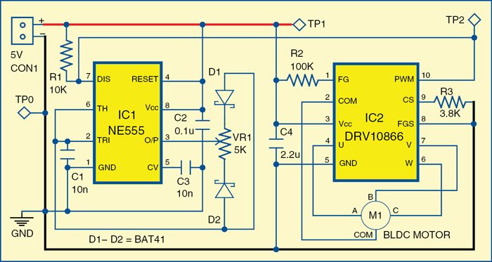


 The global Siemens research department is working with partners to develop new information and communications technology for future electric cars.
 Simplifying complexity: the electronics architecture of today's mid-range automobile (left) versus the RACE technology (right).
 The start-up of the powertrain is an important step in the installation of the RACE architecture into a vehicle.
 At the test rig, researchers from Siemens are gradually integrating and testing the software functions on the final control units as installed in the vehicle.
 Today a vehicle may contain over 70 different control units that are all networked with one another. Added to this are thousands of sub-functions that run on these control units.
 In the RACE project, cars are controlled by a centralized computing architecture, similar to the fly-by-wire systems used in today's airplanes.


.jpg "The transmitter & receiver technology improves inductive gap sensor technology by enabling it to both measure the gap and send data between two devices with the same sensor.")
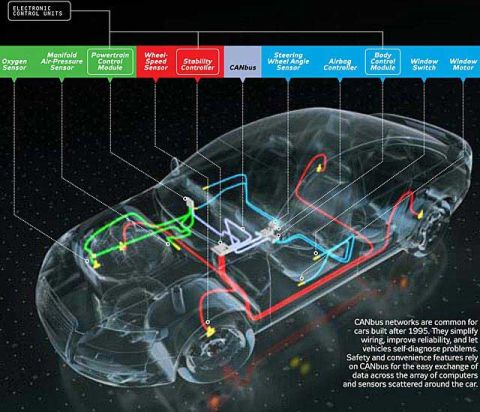


