Towards quantum thermodynamics in electronic circuits
Electronic circuits operating at sub-kelvin temperatures are attractive candidates for studying classical and quantum thermodynamics: their temperature can be controlled and measured locally with exquisite precision, and they allow experiments with large statistical samples. The availability and rapid development of devices such as quantum dots, single-electron boxes and superconducting qubits only enhance their appeal. But although these systems provide fertile ground for studying heat transport, entropy production and work in the context of quantum mechanics, the field remains in its infancy experimentally. Here, we review some recent experiments on quantum heat transport, fluctuation relations and implementations of Maxwell’s demon, revealing the rich physics yet to be fully probed in these systems.
figure Dissipation and relaxation in electronic circuits at low temperatures.

a, A generic thermal model. A system, for example, a charge state in a single-electron experiment or qubit, is driven by a source of work. The system interacts with the Fermi-distributed electrons, which, in turn, tend to thermalize .
Figure : Testing the fluctuation theorem in equation (1) experimentally.

a, A double quantum-dot (DQD) circuit . The physical positions of the dots for (n1, n2) electrons between source and drain are indicated by white circles. A quantum point contact (QPC) reads the charge state on the dots. b, A time track .
Figure Experimental realization of the Jarzynski fluctuation relation.

Figure Experimental realization of the Jarzynski fluctuation relation.
a, A schematic diagram of a metallic single-electron box . The box is connected capacitively to its environment by CL and CR, and the two metallic electrodes are connected through a tunnel junction with capacitance Cj.
Figure : Experimental implementation of Maxwell’s demon.

a, The principle and the protocol of the experiment on a single-electron box34. Initially, the two-level (in this case, classical) system is positioned such that the system is in one of the charge states. The control parameter ng .

Bio-sign monitoring. Thin polymer membranes incorporating electronics circuits are small enough to be introduced into mattress fabrics, and, being in contact with the skin surface during sleep, would mean that smart pillowcases or sheets could monitor body temperature, skin moisture levels, indicating stress or relaxation, electrical nerve activity, indicative of sleep phases or dream states, allowing alarms to wake someone at the optimal part of a sleep cycle instead of disturbing dreams and waking someone feeling groggy .
“The advances in technology, particularly in the sleep sector are mind-blowing and we’re incredibly excited about the innovations and developments soon to be at our fingertips. As leaders in sleep technology and innovation, Sealy is committed to designing products that deliver on comfort, support and most importantly, provide a great night’s sleep .
Electro active polymers are developing quickly and can emulate muscles contracting when a voltage is applied. These will be woven into smart fabrics that can alter shape or tension. These would allow a mattress to vary in firmness to each customer’s preference. These can even be app-adjusted or automatically reactive to enable active personalized support.
Smart beds that wake you up when you’ve finished a dream – thin polymer membranes incorporating electronics circuits can be incorporated into fabrics, meaning that smart pillowcases or sheets could monitor body temperature and skin moisture levels to indicate stress or relaxation. Electrical nerve activity, indicative of sleep phases or dream states, will also allow alarms to wake someone at the optimal part of a sleep cycle instead of disturbing dreams and waking someone feeling groggy. Similar reciprocation of that same technology would also allow thought recognition, which has already proven sophisticated enough to recognize what a dreamer is dreaming about.
Levitating mattress – using graphene, a relatively new material with amazing properties, this material is a near perfect conductor, making it ideal for circuitry. That means near-sci-fi mattress technology would be feasible, such as magnetic levitation. Electronic magnetic ‘muscles’ could be incorporated into fabrics or filling that would allow a high degree of support variability and control. They could even be used to convert body movement into electricity to power other devices and sensors.
X . I smart home of the future
We’ve all been there. Halfway to the airport and suddenly gripped by the unshakable fear that we’ve forgotten to switch off the oven or lock the windows. With a smart home, you can put your mind at rest and fix any little oversights, all from your phone as you speed toward your flight.
In a smart home, all the electronic devices are connected to one another in one controllable network, allowing inhabitants to interact with their homes like never before and offering greater comfort, convenience, personalisation, energy savings and opportunities for fun!
Want your coffee maker to crank up downstairs as soon as you throw back your sheets? A smart home will let you arrange that. Want to start the bread maker churning and the pool heating as you leave the office? You can do that too. Want your home to learn your habits and help cut your energy consumption, or to notify you if it senses anything untoward like an intruder? No problem at all.

The basis for all these technological advances is the ‘Internet of Things’ – the exponentially expanding web of devices that are connected to the Internet, allowing them to talk to each other and to you, transforming the way we live.
Automated home electronics have been on the scene for decades, but only recently have they been able to begin talking to one another and functioning in concert. That’s largely thanks to the advent of efficient low-cost wireless protocols – think Wi-Fi, Bluetooth, mobile phone networks – in the early-2000s, which use radio waves to transmit messages wirelessly.
Zig Bee and Z-Wave are similar protocols that can be thought of as low-power versions of Wi-Fi. They are ideal for use inside the smart home because they’re optimized for transmitting small amounts of data – like messages to and from smart devices – through walls and furniture, over the range of a typical household.
Smart devices are connected via these wireless networks to a central hub where they can be controlled with a tablet or smartphone. They can also be programmed to carry out any action based on the logic command ‘If This Then That’, or IFTTT (rhymes with lift). IFTTT lets you dictate what action a device should take for a given stimulus.
For example, announcing to your TV, “It’s movie time”, might lower the shades, dim the lights, activate your surround sound system and fire up the popcorn maker. Now that’s smart.
How do ovens cook food?

There are two main varieties of household oven – gas and electric – with a few hybrids between the two.
The former work by burning gas to warm a heating element and/or a metal cooking compartment directly. The gas supply is ignited using an electric lighter that proceeds through one or more burner units to warm the air in the oven compartment(s) to the temperature designated by the thermostat.
Within the category of gas ovens there are two major types: those that use heating elements – strips of metal in the top and bottom of the oven, and those that heat a metal cooking compartment directly. In both cases, the oven works by emitting thermal radiation, either baking (heated from below) or broiling (heated from above) the food. As a general rule, compartments utilise indirect heat, while elements point heat in a specific direction.
Electric ovens also come in two main flavours: standard thermal radiation and convection. Thermal electric ovens work on the same principle as their gas counterparts, with metal elements. Here the energy source is electricity, which passes as a current through the inner, coiled wires of the elements.
Convection ovens are of similar construction to standard thermal radiation cookers but introduce an air-circulating fan into the mix. This fan, which is installed in the rear wall of the oven cavity, aims to distribute the directed radiation from the heating elements around the oven, thereby delivering a more even spread of heat and a faster, more balanced cooking environment as a result.

The ABC’s of Smart Home Technology
I recently earned my certification for Smart Home technology, and think that is a feature of homes that is just beginning to grow. Below is an article I found that may be useful for those who have a home and are interested in making it smart- generally the starter pack of items to convert your home over can be as low as $1500 installed- however can quickly go up from there. It is estimated that homes with just the starter pack of smart home technology can increase their value and increase the number of buyers by adding these simple features.

is the year you make your home smart? It might seem like a large undertaking, but today’s smart home products are easier than ever to install and use. We’ve compiled an A-Z guide to smart home technology, buzzwords and trends below:
A is for Automation – Dreaming of a ‘Jetsons’ home? Today’s smart home technology can do everything from order your groceries to dim your lights, and the technology is only getting better by the day. Check out some of the newest products unveiled at this year’s CES.
B is for Buyers and Sellers – Smart home products are beneficial to both buyers and sellers. That’s right – you can leave pre-installed smart home products in the home you’re selling. A 2016 survey by Coldwell Banker found that 44% of Americans believe smart home technology should already be installed in homes for sale.
C is for Cost-Savings – You probably already know this, but smart home technology can save you money. Smart thermostats can reduce unnecessary cooling and heating expenses and smart lighting can help you curb your energy consumption and reduce your electric bills.
D is for Don’t Want to Get Up – We all have our lazy moments. Imagine you never had to get up to turn off the lights before bed. Imagine you didn’t have to leave the warmth of your blanket to turn up the heat. Smart home tech enhances life’s simple comforts.
E is for Entertainment – Smart TVs, sound systems, content streaming, gaming and more. Smart home technology expands the possibilities for how we lay back and relax at home. You’ll never binge watch your shows the same way after you see them in high definition clarity and connected to your smart sound system and streaming system.
F is for Fridge – How many times have you gotten to the supermarket and realized you left your grocery list at home? Imagine you could look inside your smart fridge from your phone to see what was missing? These are the possibilities available with today’s suite of smart refrigerators.
G is for Green – We’ve already covered the cost-saving benefits of smart home technology. Beyond saving you some green, it can help reduce your home’s environmental impact and help you go green!
H is for Hubs – You might have heard of things like Apple’s HomeKit, Samsung’s SmartThings and Google’s Thread. These three are examples of hubs, which help connect multiple smart home devices across many brands and capabilities under one platform, simplifying your smart home experience.
I is for Integration – You may have heard a lot of buzz around the word smart home integration, which goes hand-in-hand with hubs. Integration means multiple products are able to work along with one another. An example is an Amazon Echo working with your Nest thermostat.
J is for “Just for the Tech Savvy” – This is actually a big smart home myth! Smart home technology is for everyone along all ends of the technology spectrum.
K is for Kit (the Smart Home Staging Kit, that is) – Did you know that Coldwell Banker curated the first-ever Smart Home Staging Kit? The kit includes a Nest Thermostat, Nest Protect, Nest Cam, August Smart Lock, August Connect and Lutron Caseta Wireless Lighting Products. The kit is available at SmartHomeStaging.com, or you can speak to a Coldwell Banker agent to take advantage of exclusive promotional pricing.
L is for Lighting – One of the most popular smart home categories is smart lighting. Much of today’s technology can help you control your home’s lighting remotely via a smart phone app. Some products can help you transform a room using dimming features to create a more dynamic and versatile living space.
M is for Mainstream – Smart home is now in the mainstream, but it isn’t too late to hop on the bandwagon. Think about areas of your home that could use a convenience upgrade and take a leap. Bring your home into the 21st century!
N is for News – Coldwell Banker lived stream news about smart home technology straight from the floor during CES 2017 this year in Las Vegas. Now you can check out Blue Matter for everything you need to know about smart home in 2017.
O is for One At a Time – Introduce new smart home products one at a time so you can get acclimated and learn each device’s functionality. Our agents turned smart home gurus agree and suggest starting with one product you know will improve your day-to-day life if you are skeptical of adding smart home features. Dip your toes into the pool before you dive in!
P is for Presents – While the holidays have come and gone, smart home technology can make a great gift for a loved one or friend throughout the year. Check out our most recent smart home gift guide!
Q is for Q&A – Of course, it’s normal to have questions. The good news? Coldwell Banker launched a first of its kind smart home education program in consort with CEDIA. This makes our agents the foremost experts in all things smart home – and more than willing to answer your questions.
R is for Real Estate – Coldwell Banker has been attending and sponsoring CES for the past three years. Why is a real estate company investing in a tech show? Smart home technology is no longer a prediction for the future – it is in our present, and is a growing part of the real estate industry.
S is for Security – Smart security cameras, smoke alarms, door locks and more. There is a smart home product to protect every corner of your home whether you are near or far.
T is for Thermostats – Smart thermostats can control both your heating and cooling. Besides the cost-saving functionality we discussed earlier, these thermostats can also make your home a bit cozier before you arrive. You can control your A/C remotely to turn on a few minutes before you arrive home on a sweltering day. Same goes for your heat on a particularly frosty day.
V is for Voice Control – According to our 2017 Smart Home Marketplace survey, voice control is the next big thing in smart home technology. 72% of Americans who have smart home products – controlled remotely by a smartphone, tablet, computer or by a separate automatic system within the home itself – want voice control. Voice control technology has quickly evolved with the advent of platforms like Amazon’s Alexa and Google Home.
W is for Wi-Fi – At the root of all smart home technology is Wi-Fi. All of these products require an internet connection in order to function with the devices around them and your smart phone.
X is for XOXO – how you are going to want to thank your home after it’s decked out with smart home technology.
Y is for You – It’s up to you! Once you make the decision to introduce smart home elements to your home, installing smart home technology can be a fun DIY project.
Note: The letters U and Z were purposefully omitted.
X . II Bedroom From The Future

Oral B has already come up with a smart mirror prototype similar for bathroom and according to Betta Living, such mirrors will become a common thing in bedrooms in about 5 years. The mirror, of interactive nature, will display the contents of your wardrobe and users shall also be able to virtually try clothes on them by using gestural technology and micro-tagging.
The amazing mirror will also double up as user’s personal stylist which will be able to suggest what people should wear based on weather and events. Users shall also have the facility to make online purchases and find matching shoes and accessories to the existing items. Clear glass windows will be superseded by smart windows, allowing the users to see scenes of their choice while also automating the windows to time of the day. The smart window would transform into an interactive screen to watch TV, check up on weather and navigate through social media accounts. Samsung has a similar design known as Transparent Smart Window. As for mattresses and beds, a cantilever mechanism will be used to store them in the ceiling instead of walls.

The bed that would disappear into the ceiling at the touch of a button must be very high-tech. It will have multiple sensors for the users to set optimal temperature, monitor the body temperature and raise alarm in case of an emergency. The in-built cooling mechanism of the bed will cool down the user’s body to match optimal temperature in order to prevent night sweats. Pillows shall have light technology incorporated into them and will light up gradually as the user wakes up.
Future bedrooms will induct automation systems that will personalize even minor things to meet a user’s needs and requirements. Moreover, the bedroom will make way for a home gym, upon elevating the bed. The intended gym will be similar to Domyos Training Box which shall house a weight lifting bar, different set of weights, weight bench, cardio setup and mat in a storage box.

The flooring could be interchangeable by a simple press of a button whereas the room shall be decorated with 3D frames, ornaments, vases and other stuff that will be designed and made at home. By making use of Roomba vacuums or Dyson’s automated vacuums, user shall be able to clean the room. Barry Rourke said, “Our bedroom of the future is all about multi-functionality to make the most of space, fabulous design and making home comforts even more sophisticated.”
“As people flock to popular urban areas, domestic spaces are shrinking but in our transformative bedroom, even the smallest of spaces will not restrict the homeowners in the future. Windows will adapt to whatever we want our view to be and interactive living surfaces will mean we have access to our lives and wardrobe in one clever screen. Even the traditional bed will become tech driven and be linked to everything else in the room by clever sensors and smartphones. There are so many exciting things being developed that our problem designing the bedroom of the future was what to leave out.”


X . II Engineering energy to the what is Standalone Solar Electric System?
standalone solar system are solar lanterns, solar home lighting systems, solar water pumping systems, etc. As the sun is the only source of energy in this system it should have some means to make it active even in night times.
Types of Standalone Solar Systems
Depending upon the use and design there are different types of standalone solar systems.- Standalone Solar (PV) system with only DC load
- Standalone Solar (PV) system with DC load and Electronics control circuitry
- Standalone Solar (PV) system with DC load, Electronics control circuitry and Battery
- Standalone Solar (PV) system with AC/DC load, Electronics control circuitry and Battery.
Standalone Solar (PV) System with only DC Load
This system is simplest among all the standalone solar system. Standalone Solar (PV) System with only DC Load requires only two main components one the solar module array where the electricity is generated and one or more DC loads where the electricity is consumed. This system serves only during sunny day times. The configuration of this system is quite simple as we told earlier here the solar module array is directly connected to the load no other arrangement is required in between. It is quite natural that the rate of production of electricity in this system varies throughout the day depending upon the intensity and incidence angle of the sunlight. This makes the applications of Standalone Solar (PV) System with only DC Load limited to some specific electrical appliances where the precise operation is not essential. This standalone solar system can be successfully utilized for pumping drinking and irrigation water as in these both cases fixed amount of water is not required to lift every hour. DC fan can be operated by this system when speed of the fan is not required to be constant throughout the day. In this system the speed of the fan is maximum when the intensity of sunlight is maximum. Hence, maximum pleasant air flow is achieved during maximum hot period of the day times.
 Standalone Solar (PV) System with DC Load and Electronic Control Circuit
Standalone Solar (PV) System with only DC Load can be improved by adding an electronic control circuit. This added electronic control circuit to the system, improves the utilization of power generated by the solar module array. This electronic control circuit is normally an electronic solar charge controller (SCC) (voltage or current regulator) or a maximum power point tracker (MPPT). The main purpose of these circuits is to provide regulated current and voltage to the load. The MPPT circuit is used to extract maximum power from the solar modules under all conditions. Thus, it ensures the best utilization of solar PV modules.
Standalone Solar (PV) System with DC Load, Electronic Control Circuit and Battery
A standalone system can be more practical and usable if it is able to serve even in absence of sunlight that is in night times. This can be simply done by adding a storage battery in the system which stores electricity produced during day times. This stored electricity can be utilized when there is no sunlight and in night times. After adding a suitable rated battery, the system becomes a Standalone Solar (PV) System with DC Load, Electronic Control Circuit and Battery. It is needless to say that this standalone system has four basic components- Solar Module Array
- Electronics Control Circuit
- Storage Battery System and
- DC Load
 Here solar module charges the battery during daytimes and the battery supplies the load both during day and night. The electronic control circuit plays a vital role here it actually controls the flow of charges into the battery and out of the battery depending upon the system conditions and demands. The control circuit also protects the battery from overcharging as well as over-discharging. This system is most commonly used in solar street light system in remote villages. LED based solar lanterns which nowadays widely available in the local market are popular examples of Standalone Solar (PV) System with DC Load, Electronic Control Circuit and Battery.
 Standalone Solar (PV) System with AC/DC Load, Electronic Control Circuit and Battery
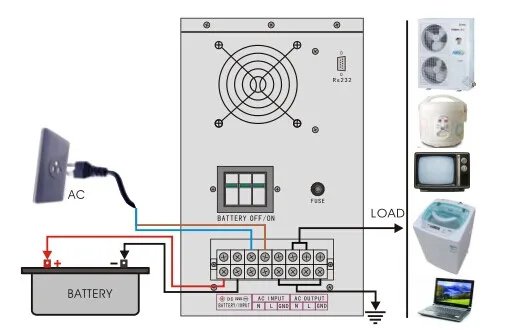
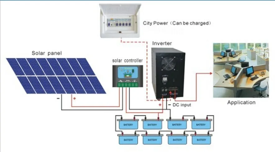
So far we have discussed about the standalone solar energy systems which can only be used for operating DC load but maximum numbers of equipments we use in our daily life are AC operated so some means is required to attach with the solar energy system so that we can run AC equipment as well with standalone solar system. Inverter is a device which converts DC to AC of specified voltage and frequency. Inverter is basically a DC to AC converter whose input is DC and output is AC of desired voltage and frequency. So if we connect an inverter across the DC output terminals of electronic control device along with the DC load then the system becomes able to run AC equipments as well. As this system can operate both DC and AC load, the system becomes most popular version of standalone solar energy system. Nearly all kinds of DC and AC load can be operated by this system such as AC/DC fan, computer, TV, tube lights, CFL, LED lamps etc. This system is most suitable as alternative of grid electric supply where limited grid electric supply is available. It is needless to say that this standalone system has six basic components
 - Solar Module Array
- Electronics Control Circuit
- Storage Battery System and
- DC Load
- Inverter
- AC Load.
X . III Typical Standalone Solar Photovoltaic (SPV) System

Electrical Equivalent model of solar PV cell

Incremental conductance method


Unlike hybrid systems, grid-tie solar systems are not able to function or generate electricity during a blackout or power outage due to safety reasons; since blackouts usually occur when the electricity grid is damaged. If the solar inverter was still feeding electricity into a damaged grid it would risk the safety of the people repairing the fault/s in the network. However most hybrid solar systems with battery storage are able to automatically isolate from the grid (known as islanding) and continue to operate during a blackout.
Batteries are able to be added to an on-grid solar system at a later stage if required. The popular Tesla Powerwall 2 is an AC battery which can be added to an existing solar system.

X . IIIIII Unipolar Switching Full Bridge Modules Make Solar Inverters More Efficient


========= MA THE BED ELECTRONIC SYSTEM TO GOGMOR MATIC =========
In recent times, the overwhelming consumption of fossil fuels for various energy needs has reflected a big danger to our environment. Electricity generation from fossil fuels (like coal, gas and other petroleum products) in various thermal power plants across the world is the most hazardous sector for our environmentally safe society. Different greenhouse gases (GHGs) like CO 2 , CO, SO 2 , NO x and other pollutants are the uncontrolled byproducts from these thermal power plants. These GHGs pollute the environment at a very severe level and causes many dangerous and fatal diseases in humans, animals and plants in our society. The massive production of these poisonous gases not only leads to many health problems but it also contributes to the biggest climate change challenge called global warming. Global warming is the biggest challenge and a frontier to work upon for a sustainable and ecologically balanced society. Due to global warming, the various environment related problems like flood and drought may arise in different part of the world. Apart from all these ecological problems, one more factual point is important that the fossil fuels will not be available to be dependent upon for a long time. Fossil fuels are depleting day by day due to their uncontrolled and extensive consumption in power plants, automobile and other energy applications. Due to all these facts, the solar energy has drawn attention of energy professionals for electrical power generation for many years. The efficiency of solar power generating system using photovoltaic (PV) technology [1] is the most important parameter in utilizing the solar PV systems. The efficiency represents the maximum power output from solar PV power system. The maximum power output can be achieved by an electronic tracking of maximum power points (MPPs) on the characteristic curve of solar PV module. The MPPs can be tracked by a power electronic circuitry called maximum power point tracker (MPPT) [2]. In a MPPT, a DC-DC converter is used to adjust the output voltage from PV module to the load in such a way that it indicates the maximum possible power on the characteristic curve. The operation of DC-DC converter [3] is carried out by its electronic switch (usually MOSFET). The switching is controlled by means of a control algorithm. Many MPPTs have been discussed and developed till date. In this paper, we not only discuss some of the existing MPPT techniques [4-6] and suggest a new proposed fill factor based MPPT techniques for the improved version of MPPT for maximized efficiency. A complete standalone solar PV system comprises of the following components, solar PV module(s), maximum power point tracker (MPPT), electrical load, charge controller, battery, inverter (for ac loads). Figure 1 represents a typical solar PV power system. The characteristics of PV module are the basic requirement for tracking the maximum power points (MPPs) using any MPPT technique. For characterizing the solar PV module, it is required to model the characteristic equation from an electrical equivalent of solar cell (module) as in following figure 2:
illustrations science solar cell system array DC-DC converter load DC-AC inverter AC load battery charge discharge controller electrical power grid electricity electronics energy conversion ecology ecological alternative technology technological panel environmentalism environmentally friendly renewable resource radiant photovoltaic semiconductor PV grid-connecting power grid diagram figure flow horizontal
Controller in the solar street lamp system can be said as "brain" because its function is as a regulator of electric current both to the incoming currents and outflows, in addition we can control it easily without a complicated thing. This purpose of control so that if there is any damage to solar street lights system then we can easily fix it. How it works charger controller At the time of solar panels get energy from daylight sun, this charger controller circuit work, charge (charge) battery and keep the battery voltage to keep it stable.
Example:
If we use 12V battery, then this circuit will keep the charger voltage 12 10%, charger voltage that is needed between 13,2 - 13,4 Volt.
and when it reaches the voltage, this circuit will automatically stop the process of charging the battery.
Conversely, if the battery voltage drop / drop up to 11 Volt, then the controller will break the voltage so that the battery is not up.
Overall Function of this Controller that is to keep the battery is not excess (over charger) and run out of voltage (under charger) with so then the age of the battery grows longer.
Thus we do not need to recharge the battery at any time, otherwise it is more efficient because the structure of the control circuit is more automatic.
There are also ways of controlling it will be explained clearly as follows:
1. It only requires a detection device to know whether the battery is occupied or not yet when the voltage in the battery is fully charged, the controller will stop the electric current from entering the battery in order to keep the battery life much more durable.
2. When the voltage in the battery is almost empty, the controller functions to stop taking the electric current from the battery by the load / electrical equipment. In a certain voltage level (generally about 10% of the remaining voltage in the battery), the disconnection is performed by the controller. As for this the battery is more durable and prevents damage to the battery cells. In most controller models, the lamp indicator lights up with a certain color (usually red or yellow) indicating that the voltage in the battery is running low and is necessary for charging. In this condition, although the remaining voltage in the battery still exists, but due to the taking of electrical current from the battery has been disconnected by the controller, then the electrical / load equipment can not operate.
Back to the incident, namely that the events occurring in the solar street lamp system can be various, among others, the zipper, full battery, weak battery, normal battery, over-voltage, etc., as all these events can be detected by controller. Because the role is quite important, the controller is highly recommended to be installed even if not absolute.
Controller in the solar street lamp system can be said as "brain" because its function is as a regulator of electric current both to the incoming currents and outflows, in addition we can control it easily without a complicated thing. This purpose of control so that if there is any damage to solar street lights system then we can easily fix it. How it works charger controller At the time of solar panels get energy from daylight sun, this charger controller circuit work, charge (charge) battery and keep the battery voltage to keep it stable.
Example:
If we use 12V battery, then this circuit will keep the charger voltage 12 10%, charger voltage that is needed between 13,2 - 13,4 Volt.
and when it reaches the voltage, this circuit will automatically stop the process of charging the battery.
Conversely, if the battery voltage drop / drop up to 11 Volt, then the controller will break the voltage so that the battery is not up.
Overall Function of this Controller that is to keep the battery is not excess (over charger) and run out of voltage (under charger) with so then the age of the battery grows longer.
Thus we do not need to recharge the battery at any time, otherwise it is more efficient because the structure of the control circuit is more automatic.
There are also ways of controlling it will be explained clearly as follows:
1. It only requires a detection device to know whether the battery is occupied or not yet when the voltage in the battery is fully charged, the controller will stop the electric current from entering the battery in order to keep the battery life much more durable.
2. When the voltage in the battery is almost empty, the controller functions to stop taking the electric current from the battery by the load / electrical equipment. In a certain voltage level (generally about 10% of the remaining voltage in the battery), the disconnection is performed by the controller. As for this the battery is more durable and prevents damage to the battery cells. In most controller models, the lamp indicator lights up with a certain color (usually red or yellow) indicating that the voltage in the battery is running low and is necessary for charging. In this condition, although the remaining voltage in the battery still exists, but due to the taking of electrical current from the battery has been disconnected by the controller, then the electrical / load equipment can not operate .
Back to the incident, namely that the events occurring in the solar street lamp system can be various, among others, the zipper, full battery, weak battery, normal battery, over-voltage, etc., as all these events can be detected by controller. Because the role is quite important, the controller is highly recommended to be installed even if not absolute.
X . IIII Photovoltaic Off-grid Inverter
Photovoltaic Off-grid Inverter Market provides detailed market segment level data on the international market. The Photovoltaic Off-grid Inverter market report addresses forecast and growth patterns by company, regions and type or application from 2017 to 2022.The Photovoltaic Off-grid Inverter market research report introduce incorporates analysis of definitions, classifications, applications and industry chain structure. Besides this, the Photovoltaic Off-grid Inverter market report also consists of development trends, competitive landscape analysis, and key regions development status.
The report starts with a basic Photovoltaic Off-grid Inverter market overview. It also acts as a vital tool to industries active across the value chain and for new entrants by enabling them to take advantage of the opportunities and develop business strategies.
Photovoltaic Off-grid Inverter market report helps the companies to better understand the market trends and to grasp opportunities and articulate critical business strategies. Also includes company profiles of market key players contact information, gross capacity, product details of each firm, price, and cost are covered. Photovoltaic Off-grid Inverter Market by Product Type: Stand-alone inverters, Grid-tie inverters, Battery backup inverters Major Applications of Photovoltaic Off-grid Inverter Market: Urban Area, Rural Areas.
This section of the Photovoltaic Off-grid Inverter market research report includes analysis of major raw materials suppliers, manufacturing equipment suppliers, major players of the Photovoltaic Off-grid Inverter industry, key consumers, and supply chain relationship. The contact information is also provided along with this analysis. Several important areas are covered in this Photovoltaic Off-grid Inverter market research report. Some key points among them: – Photovoltaic Off-grid Inverter Market Competition by Manufacturers Photovoltaic Off-grid Inverter Production, Revenue (Value) by Region (2011-2016) Photovoltaic Off-grid Inverter Supply (Production), Consumption, Export, Import by Regions (2011-2016) Photovoltaic Off-grid Inverter Production, Revenue (Value), Price Trend by Type Photovoltaic Off-grid Inverter Market Analysis by Application Photovoltaic Off-grid Inverter Manufacturers Profiles/Analysis Photovoltaic Off-grid Inverter Manufacturing Cost Analysis Industrial Chain, Sourcing Strategy and Downstream Buyers Marketing Strategy Analysis, Distributors/Traders Market Effect Factors Analysis Photovoltaic Off-grid Inverter Market Forecast (2016-2022).
Along with this, analysis of depreciation cost, manufacturing cost structure, manufacturing process is also carried out. Price, cost, and gross analysis of the Photovoltaic Off-grid Inverter market is also included in this section.
The Photovoltaic Off-grid Inverter market research report shed light on Foremost Regions: North America, Europe, China, Japan, Southeast Asia, India. The Photovoltaic Off-grid Inverter industry research report is a valuable source of guidance and direction. It is helpful for established businesses, new entrants in the market as well as individuals interested in the market. The Photovoltaic Off-grid Inverter market report provides important statistics on the existing state of the said market.
dc to ac 3 phase solar inverter with lcd display
X . IIIII solar power systems
The three main types of solar power systems are:
1. On-grid - also known as a grid-tie or grid-feed solar system
2. Off-grid - also known as a stand-alone power system (SAPS)
3. Hybrid - Solar plus battery storage with grid-connection

All solar systems include:
Solar panels:
Solar panels or solar modules are installed together in what is known as a solar array. Modern solar panels are made up of many solar cells or photovoltaic (PV) cells which generate direct current (DC) electricity from sunlight or energy from the sun. Note: It is light energy or irradiance, not heat, which produces electricity in photovoltaic cells.Solar inverter:
Solar panels generate DC electricity which needs to be converted to alternating current (AC) electricity for use in our homes and businesses. This is the role of the solar inverter. In a string inverter system, solar panels are linked together in series and the DC electricity is brought to a single inverter which converts the DC to AC. In a micro inverter system, each panel, or every two panels, has it’s own micro inverter attached to the back side of the panel. The panel still produces DC, but is converted to AC on the roof, and is fed straight to the electrical switchboard.Switchboard:
(electricity consumption.) AC electricity is sent to the switchboard where it is directed to the various circuits and appliances in your house that are using electricity at the time. Any excess electricity is sent to either a battery storage system if you have a off-grid or hybrid system, or to the electricity grid if you have an on-grid system.
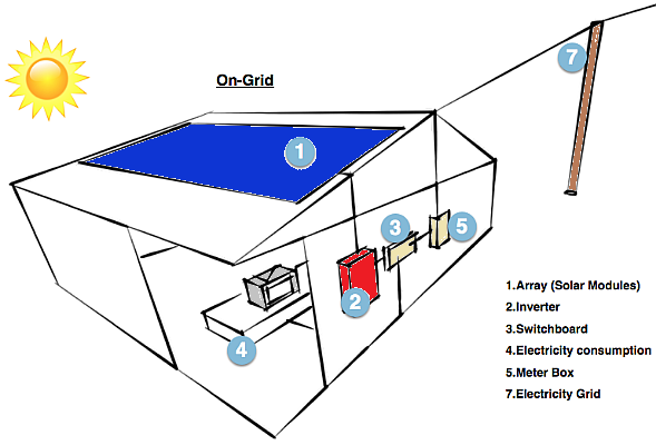
On-Grid System
On-grid or grid-tie solar systems are by far the most common and widely used by homes and businesses. These systems are connected to the public electricity grid and do not require battery storage. Any solar power that you generate from an on-grid system (which is not used directly in your home) is exported onto the electricity grid and you usually get paid a feed-in-tariff (FiT) for the energy that you export.Unlike hybrid systems, grid-tie solar systems are not able to function or generate electricity during a blackout or power outage due to safety reasons; since blackouts usually occur when the electricity grid is damaged. If the solar inverter was still feeding electricity into a damaged grid it would risk the safety of the people repairing the fault/s in the network. However most hybrid solar systems with battery storage are able to automatically isolate from the grid (known as islanding) and continue to operate during a blackout.
Batteries are able to be added to an on-grid solar system at a later stage if required. The popular Tesla Powerwall 2 is an AC battery which can be added to an existing solar system.
In an on-grid system, this is what happens after electricity reaches the switchboard:
- The meter. Excess solar energy runs through the meter, which calculates how much power you are either exporting or importing (purchasing).
- Metering systems work differently in many states and countries around the world. In this description I am assuming that the meter is only measuring the electricity being exported to the grid, as is the case in most of Australia. In some states, meters measure all solar electricity produced by your system, and therefore your electricity will run through your meter before reaching the switchboard and not after it. In some areas (currently in California), the meter measures both production and export, and the consumer is charged (or credited) for net electricity used over a month or year period. I will explain more about metering in a later blog.
- The electricity grid. Electricity that is sent to the grid from your solar system can then be used by other consumers on the grid (your neighbours). When your solar system is not operating, or you are using more electricity than your system is producing, you will start importing or consuming electricity from the grid.
Off-Grid System
An off-grid system is not connected to the electricity grid and therefore requires battery storage. An off-grid solar system must be designed appropriately so that it will generate enough power throughout the year and have enough battery capacity to meet the home’s requirements, even in the depths of winter when there is less sunlight. The high cost of batteries and inverters means off-grid systems are much more expensive than on-grid systems and so are usually only needed in more remote areas that are far from any electricity grid. However battery costs are reducing rapidly, so there is now a growing market for off-grid solar battery systems even in cities and towns.
There are different types of off-grid systems which we will go into more detail later, but for now I will keep it simple. This description is for an AC coupled system, in a DC coupled system power is first sent to the battery bank, then sent to your appliances. To understand more about building and setting up an efficient off-grid home see our sister site go off-grid/hybrid
- The battery bank. In an off-grid system there is no public electricity grid. Once solar power is used by the appliances in your property, any excess power will be sent to your battery bank. Once the battery bank is full it will stop receiving power from the solar system. When your solar system is not working (night time or cloudy days), your appliances will draw power from the batteries.
- Backup Generator. For times of the year when the batteries are low on charge and the weather is very cloudy you will generally need a backup power source, such as a backup generator or gen-set. The size of the gen-set (measured in kVA) should to be adequate to supply your house and charge the batteries at the same time.
Hybrid System
Due to the decreasing cost of battery storage, systems that are already connected to the electricity grid can start taking advantage of battery storage as well. This means being able to store solar energy that is generated during the day and using it at night. When the stored energy is depleted, the grid is there as a back up, allowing consumers to have the best of both worlds. Hybrid systems are also able to charge the batteries using cheap off-peak electricity (usually after midnight to 6am).
There are also different ways to design hybrid systems but we will keep it simple for now.
- The battery bank. In hybrid system once solar power is used by the appliances in your property, any excess power will be sent to your battery bank. Once the battery bank is full, it will stop receiving power from the solar system.
- The meter and electricity grid. Depending on how your hybrid system is set up and whether your utility allows it, once your batteries are fully charged excess solar power not required by your appliances can be exported to the grid via your meter. When your solar system is not in use, and if you have drained the usable power in your batteries your appliances will then start drawing power from the grid.
Simplified layout of a hybrid solar system


X . IIIIII Unipolar Switching Full Bridge Modules Make Solar Inverters More Efficient
The decrease of fossil fuel resources, the global climate and the environmental problems on the planet requiring a significant reduction of carbon dioxide emissions lead us to use the energy in a more efficient and intelligent manner. There are from now on great economical and health benefits to exploit a renewable energy and an infinite resource like the sun.
By Serge Bontemps, Microsemi Power Products Group, Power Modules
Introduction
Solar cells are used to capture the energy from the sun and generate a direct current that is converted into an alternating current compatible with the grid. The inverter performing the DC to AC conversion must exhibit the highest efficiency not to waste the energy provided by the source. A unique solution of power modules for unipolar switching DC/AC inverters has been developed to reduce the power loss.

Mode of operation of the unipolar full bridge
The size, performance, reliability and cost are very important criteria for a solar inverter and the unipolar switching DC/AC topology allows meeting the highest possible efficiency of the system, not only fundamental not to waste a precious energy but it is also essential for reducing the cost of producing electricity.
The bottom switches are operating at high frequency to minimize output filter size while top switches operate only at line frequency. By this way the inverter takes advantage of the high frequency operation with only two switches of the bridge exhibiting switching losses while the other two have only to dissipate conduction losses.
This configuration is offered in 600V and 1200V voltage rating to address the two main AC grid voltages and meet a wide range of solar cells voltages. To achieve the most compact solution at a competitive price for a frequency operation in the range of 15 kHz to 50 kHz an IGBT technology is preferred. The bottom switches operating at high frequency are built with fast NPT IGBT devices. The top switches working at line frequency feature the lowest saturation voltage, offered by Trench and Field stop IGBTs. It would be possible to implement the fast switches in the top position of the bridge and the low conduction devices in the bottom but usually the opposite is achieved to facilitate the driving of the fast devices and avoid a floating position when placed in the top of the bridge.
The diodes in these new power modules are matched to the power transistors for improved inverter efficiency as well. High speed, soft recovery Microsemi DQ diodes type is implemented in parallel with the top IGBTs to provide low recovery losses in combination with the bottom fast IGBTs. Low forward voltage diodes protect the bottom IGBTs during output zero crossings. These last diodes are much less stressed than the others that are submitted to high frequency reverse recovery which allows sizing them with a lower current rating which is appreciable for size and cost reduction.
In photovoltaic systems the size and cost of magnetic components must be as low as possible. With improved RDS(on) x Qg and RDS(on) x Esw figures of merit, 600V CoolmosTM devices operate at even higher switching frequencies with minimum switching and conduction losses making possible significant system size reduction without losing energy efficiency.
Efficiency performance evaluation of various combinations of power devices as a function of operating frequency.
Various combinations of technologies are compared in terms of efficiency as a function of output power. The study is also performed with different operating frequencies to better measure the impact of the switching losses of the different fast switches.
In order to have a fair comparison between solutions, the efficiency is given for the normalized output power P/Pnom.
To compare the largest possible range of power semiconductor types, this study is related to 600V devices. In order to avoid any audible noise and minimize the size of the magnetic components an operating frequency of 20 kHz for the fast switches is generally adopted.
Fig. 2 gives the efficiency as a function of P/Pnom for:
- A configuration using only Trench and Field stop IGBTs for all 4 switches of the bridge.
- A configuration using only fast NPT IGBTs.
- The optimized configuration with fast bottom NPT IGBTs and low conduction Trench and Field stop top IGBTs.
- A configuration using only Trench and Field stop IGBTs for all 4 switches of the bridge.
- A configuration using only fast NPT IGBTs.
- The optimized configuration with fast bottom NPT IGBTs and low conduction Trench and Field stop top IGBTs.

600V Trench and Field stop IGBTs are designed to operate up to 20 kHz. Low VCEsat voltage combined with reasonable switching times allow reaching efficiency between 96% and 97%. Despite higher conduction losses, fast NPT IGBT devices enable to improve the efficiency thanks to improved switching losses. The combination of Fast IGBTs for their low switching losses and Trench and Field stop IGBTs for low conduction characteristics outperform the previous versions by almost 1% with an overall efficiency above 98% over a wider range of input power.
In order to further improve the efficiency it is still possible to decrease the operating frequency down to 16 kHz, limit of audible noise without impacting the size of magnetic components.
The decrease from 20 kHz to 16 kHz allows getting efficiency above 97% for Trench and Field stop IGBTs, very close to 98% for fast NPT IGBTs and well above 98% for the mix of IGBT technologies (seeing Fig.2).
In some cases, it makes great interest increasing the operating frequency in the range of 50 kHz to further decrease the magnetic components, particularly on the output filter.
600 V fast NPT IGBTs with low turn off energy are fully capable of operating up to 100 kHz and therefore can achieve acceptable efficiency in the range of 50 kHz. MOSFET devices with even faster switching times can offer lower switching losses than the fastest NPT devices. As long as the MOSFET devices can also offer low conduction losses they can easily exhibit lower overall losses. For 600V, COOLMOSTM transistors offer very low RDson for minimum conduction losses with fast switching times.
The combination of fast NPT and Trench IGBTs allows efficiency still higher than 97% at 50 kHz. The combination of COOLMOSTM transistors with Trench IGBTs provides an even higher efficiency than the previous combination as shown on Fig. 3.

If the operation at high frequency is not a must to reduce the size of the inverter and a 16 kHz frequency is acceptable then the association of COOLMOSTM devices and Trench IGBTs will lead to the best efficiency. Despite the low 50Hz line frequency operation of the Trench and field stop IGBTs it is recommended to use FREDFET devices or CoolmosTM transistors with faster intrinsic diode to minimize the EMI disturbance of the system.
Another important characteristic for a solar inverter is the life time and the reliability. Also critical is the EMI/RFI generated by the inverter.
SiC diodes feature essentially zero forward and reverse recovery losses that provide a significant advantage in terms of switching noise generation and performance improvement compared to standard fast silicon diodes.
The diode recovery current affects significantly the switching turn on energy within the power switch when hard switched. Such behaviour generates a significant amount of turn on losses both in the power switch and the diode, with increasing switching frequency. It has to be noted that at the end of the recovery phase some oscillations can appear, leading to a significant amount of noise in the system that may be difficult to cancel by expensive and bulky input filters.
Faster recovery results in much lower switching loss both in the switch and the diode. The small peak current observed while a SiC diode turns off is due to the capacitive junction of the Schottky barrier device rather than to reverse recovery characteristics. As opposed to the configuration using conventional FRED diodes, no ringing or oscillations can be measured. Such quiet switching is of prime interest to reduce the size and complexity of input filters and a great help to meet severe EMI/RFI requirements.
The recovery behaviour of SiC devices is not only excellent at room temperature but also constant over a wide temperature range.
The SiC devices exhibit temperature independent switching behaviour and offer very stable operation even up to elevated junction temperatures. Switching losses using SiC diodes will remain stable compared to silicon devices where the switching losses dramatically increase with temperature.
By this way, the use of SiC diodes can significantly reduce the overall losses of a solar inverter and contribute to reach record efficiencies. Lower losses mean also lower operating junction temperatures that obviously will enhance the life time of the inverter which is crucial in solar applications.
Based on this approach, the best efficiency performance is obtained with an optimized mix of power devices technology: low conduction loss IGBTs operating at 50Hz, fast switching devices operating at high frequency, and SiC diodes combined with the fast transistors.
Targeting a minimum 16 kHz switching frequency will lead to the maximum possible efficiency as shown in Fig. 4.

Microsemi power module range for Unipolar switching DC/AC solar inverters
30A to 100A full bridge modules are proposed for 600V range and 15A to 50A devices are offered in 1200V rating. Up to 3kW output power the function is integrated in the SP1 package that exhibits a 40.8 mm x 51.6mm footprint. From 3kW to 10 kW output power the full bridge is proposed in the SP3 with a 40.8mm x 73.4mm footprint. For 600V rating the full bridge is proposed both with a mix of Trench and Field stop – Fast NPT IGBTs and Trench and Field stop – CoolmosTM transistors while 1200V modules are only proposed with a mix of IGBTs.
The solar cell voltage usually varies significantly and it is necessary to implement a step-up converter to supply the full bridge circuit from the photovoltaic devices with a regulated DC voltage. With an operation at the highest possible DC voltage, the overall efficiency of the system is optimized and cabling problems are reduced as the operating current is minimal.
Size and cost are by the same way kept at a minimum. The operating frequency of the boost converter must be as high as possible to decrease the boost inductor to a small size and weight. In general a frequency of 100 kHz is adopted, but it may be very beneficial to specify switching frequencies in the range of several hundred of kHz to significantly reduce the size of the converter. It is possible to use ultrafast IGBTs to operate up to 100 kHz, but above, MOSFETs or super junction transistors are preferred to get minimum switching losses. In the chopper circuit the Boost diode is responsible for switching losses not only in the diode but also in the switch. Microsemi latest DQ generation of Fast Recovery Epitaxial Diodes is the best option for Boost diodes operating at high frequency. However at several hundred of kHz, it makes great sense replacing the FRED diodes by SiC Schottky barrier devices. SiC diodes not only offer minimum switching losses due to their intrinsic electrical properties, but they also contribute to generate a very low level of noise in the system. Microsemi offers a complete range of Boost chopper circuits in SOT227 package that combined with the SP1 unipolar full bridges covers a power range up to 3 kW. For a power between 3kW and 10 kW the Boost switch and diode are integrated in the SP1 package which can be used in combination with the SP3 unipolar full bridges.
All the Boost modules are proposed with the widest range of power semiconductors including fast and ultrafast IGBTs, MOSFETs and super junction transistors. The Boost diodes can be either FRED devices or SiC Schottkys to cover a frequency range from tens of kHz to hundred of kHz.
All packages, SOT-227, SP1 and SP3 exhibit the same 12 mm height such that they can be mounted onto the same heatsink and assembled with the same Printed Circuit Board. The two package combination, Boost and Full bridge modules offer a great flexibility in terms of components placement and layout of the PCB. In addition this allows to better spread the heat on the heatsink that will further contribute to decrease the operating temperature of the converter and increase its reliability.
On the other hand it may be preferred to integrate both the Boost stage and the full bridge into the same package to further optimize the size of the system. To achieve this goal, Microsemi has designed two modules both in 600V and 1200V rating. For each voltage rating the two lowest power devices are offered in the 40.4mm x 93mm footprint SP4 module. The two higher power ones are integrated in the low profile SP6-P housing (62mm x 108mm footprint). For 600V products, the boost stage is made of CoolmosTM transistors while for 1200V products fast IGBTs have been adopted for space and cost savings reasons.
Fig. 5 shows a picture of the Microsemi comprehensive package range for solar inverters including the SOT-227 and SP1 for Boost choppers, SP1 and SP3 for unipolar full bridges, SP4 and SP6-P for integrated Boost and full bridge modules.
Conclusion
With a mix of low conduction and fast switching devices, unipolar switching full bridge modules offer the best efficiency performance in modern solar converters. Each of the device brings its own advantages to the system, either low conduction or fast switching properties while its drawbacks have no or minor impact to the system. The function is integrated in very compact and thermally efficient packages to achieve low size and cost and long life systems.
Only the availability of SiC switching devices, MOSFETs or IGBTs will allow to reach efficiencies better than 99% and to perform the maximum that is technically feasible.
“COOLMOS” is a trademark of Infineon Technologies AG.”
========= MA THE BED ELECTRONIC SYSTEM TO GOGMOR MATIC =========
Tidak ada komentar:
Posting Komentar