15 Ways the International Space Station is Benefiting Earth
With astronauts living and working aboard the International Space Station, NASA is learning a great deal about what it takes to create and test critical systems, efficient communications technologies and protections for the human body for a deep space mission, all of which is critical in our journey to Mars. A decade ago, the station was also designated as a national lab with some of the research time aboard the orbiting laboratory dedicated to help us here on Earth, as well.
Here are 15 ways the space station is benefiting life on Earth:
Commercializing low-Earth orbit
An exciting new commercial pathway is revolutionizing and opening access to space, fostering America’s new space economy in low-Earth orbit. For the first time, the market is expressing what research can and should be done aboard the microgravity laboratory without direct government funding. The Center for Advancement of Science in Space, or CASIS, manages half of the crew research time via the ISS National Laboratory and is filling the pipeline with a wide variety of commercial research and payloads. More than two-thirds of these projects to date have required zero funding from CASIS, and that trend is increasing. In addition, a significant portion of the commercial research taking place aboard the station is made possible by NanoRacks hardware. The company has invested privately and raised capital to provide laboratory facilities for small payloads, including CubeSats deployed from the space station, that make research faster and more affordable. NASA’s move to purchase commercial cargo resupply and crew transportation to the space station enables U.S. businesses to develop a competitive capability they also can sell as a service to others while freeing NASA resources for deep space exploration. Private sector participation provides a new model for moving forward in partnership with the government.

Supporting water purification efforts worldwide
Whether in the confines of the International Space Station or a tiny hut village in sub-Saharan Africa, drinkable water is vital for human survival. Unfortunately, many people around the world lack access to clean water. Using technology developed for the space station, at-risk areas can gain access to advanced water filtration and purification systems, making a life-saving difference in these communities. Joint collaborations between aid organizations and NASA technology show just how effectively space research can adapt to contribute answers to global problems. The commercialization of this station-related technology has provided aid and disaster relief for communities worldwide. The Water Security Corporation, in collaboration with other organizations, has deployed systems using NASA water-processing technology around the world.

Growing high-quality protein crystals
There are more than 100,000 proteins in the human body and as many as 10 billion in nature. Every structure is different, and each protein holds important information related to our health and to the global environment. The perfect environment in which to study these structures is space. Microgravity allows for optimal growth of the unique and complicated crystal structures of proteins leading to the development of medical treatments. An example of a protein that was successfully crystallized in space is hematopoietic prostaglandin D synthase (H-PGDS), which may hold the key to developing useful drugs for treating muscular dystrophy. This particular experiment is an example of how understanding a protein’s structure can lead to better drug designs. Further research is ongoing.

Bringing space station ultrasound to the ends of the Earth
Fast, efficient and readily available medical attention is key to survival in a health emergency. For those without medical facilities within easy reach, it can mean the difference between life and death. For astronauts in orbit about 250 miles above Earth aboard the International Space Station, that problem was addressed through the Advanced Diagnostic Ultrasound in Microgravity (ADUM) investigation. In partnership with the World Interactive Network Focused on Critical Ultrasound (WINFO-CUS), ADUM principal investigator Scott Dulchavsky, M.D., is taking techniques originally developed for space station astronauts and adapting them for use in Earth’s farthest corners by developing protocols for performing complex procedures rapidly with remote expert guidance and training. Medical care has become more accessible in remote regions by use of small ultrasound units, tele-medicine, and remote guidance techniques, just like those used for people living aboard the space station.

Improving eye surgery with space hardware
Laser surgery to correct eyesight is a common practice, and technology developed for use in space is now commonly used on Earth to track a patient’s eye and precisely direct the laser scalpel. The Eye Tracking Device experiment gave researchers insight into how humans’ frames of reference, balance and the overall control of eye movement are affected by weightlessness. In parallel with its use on the space station, the engineers realized the device had potential for applications on Earth. Tracking the eye’s position without interfering with the surgeon’s work is essential in laser surgery. The space technology proved ideal, and the Eye Tracking Device equipment is now being used in a large proportion of corrective laser surgeries throughout the world.

Making inoperable tumors operable with a robotic arm
The delicate touch that successfully removed an egg-shaped tumor from Paige Nickason’s brain got a helping hand from a world-renowned arm—a robotic arm, that is. The technology that went into developing neuroArm, the world’s first robot capable of performing surgery inside magnetic resonance machines, was born of the Canadarm (developed in collaboration with engineers at MacDonald, Dettwiler, and Associates, Ltd. [MDA] for the U.S. Space Shuttle Program) as well as Canadarm2 and Dextre, the Canadian Space Agency’s family of space robots performing the heavy lifting and maintenance aboard the International Space Station. Since Nickason’s surgery in 2008, neuroArm has been used in initial clinical experience with 35 patients who were otherwise inoperable.

Preventing bone loss through diet and exercise
In the early days of the space station, astronauts were losing about one-and-a-half percent of their total bone mass density per month. Researchers discovered an opportunity to identify the mechanisms that control bones at a cellular level. These scientists discovered that high-intensity resistive exercise, dietary supplementation for vitamin D and specific caloric intake can remedy loss of bone mass in space. The research also is applicable to vulnerable populations on Earth, like older adults, and is important for continuous crew member residency aboard the space station and for deep space exploration to an asteroid placed in lunar orbit and on the journey to Mars.

Understanding the mechanisms of osteoporosis
While most people will never experience life in space, the benefits of studying bone and muscle loss aboard the station has the potential to touch lives here on the ground. Model organisms are non-human species with characteristics that allow them easily to be reproduced and studied in a laboratory. Scientists conducted a study of mice in orbit to understand mechanisms of osteoporosis. This research led to availability of a pharmaceutical on Earth called Prolia® to treat people with osteoporosis, a direct benefit of pharmaceutical companies using the spaceflight opportunity available via the national lab to improve health on Earth.

Developing improved vaccines
Ground research indicated that certain bacteria, in particular Salmonella, might become more pathogenic (more able to cause disease) during spaceflight. Salmonella infections result in thousands of hospitalizations and hundreds of deaths annually in the United States. While studying them in space, scientists found a pathway for bacterial pathogens to become virulent. Researchers identified the genetic pathway activating in Salmonella bacteria, allowing the increased likelihood to spread in microgravity. This research on the space station led to new studies of microbial vaccine development.

Providing students opportunities to conduct their own science in space
From the YouTube Space Lab competition, the Student Spaceflight Experiments Program, and SPHERES Zero Robotics, space station educational activities inspire more than 43 million students across the globe. These types of inquiry-based projects allow students to be involved in human space exploration with the goal of stimulating their studies of science, technology, engineering and mathematics. It is understood that when students test a hypothesis on their own or compare work in a lab to what’s going on aboard the space station, they are more motivated towards math and science.

Breast cancer detection and treatment technology
A surgical instrument inspired by the Canadian Space Agency’s heavy-lifting and maneuvering robotic arms on the space station is in clinical trials for use in patients with breast cancer. The Image-Guided Autonomous Robot (IGAR) works inside an MRI machine to help accurately identify the size and location of a tumor. Using IGAR, surgeons also will be able to perform highly dexterous, precise movements during biopsies.

Monitoring water quality from space
Though it completed its mission in 2015, the Hyperspectral Imager for the Coastal Ocean (HICO) was an imaging sensor that helped detect water quality parameters such as water clarity, phytoplankton concentrations, light absorption and the distribution of cyanobacteria. HICO was first designed and built by the U.S. Naval Research Laboratory for the Office of Naval Research to assess water quality in the coastal ocean. Researchers at the U.S. Environmental Protection Agency (EPA) took the data from HICO and developed a smartphone application to help determine hazardous concentrations of contaminants in water. With the space station’s regular addition of new instruments to provide a continuous platform for Earth observation, researchers will continue to build proactive environmental protection applications that benefit all life on Earth.

Monitoring natural disasters from space
An imaging system aboard the station, ISS SERVIR Environmental Research and Visualization System (ISERV), captured photographs of Earth from space for use in developing countries affected by natural disasters. A broader joint endeavor by NASA and the U.S. Agency for International Development, known as SERVIR, works with developing nations around the world to use satellites for environmental decision-making. Images from orbit can help with rapid response efforts to floods, fires, volcanic eruptions, deforestation, harmful algal blooms and other types of natural events. Since the station passes over more than 90 percent of the Earth’s populated areas every 24 hours, the ISERV system was available to provide imagery to developing nations quickly, collecting up to 1,000 images per day. Though ISERV successfully completed its mission, the space station continues to prove to be a valuable platform for Earth observation during times of disaster.

Describing the behavior of fluids to improve medical devices
Capillary Flow Experiments (CFE) aboard the space station study the movement of a liquid along surfaces, similar to the way fluid wicks along a paper towel. These investigations produce space-based models that describe fluid behavior in microgravity, which has led to a new medical testing device on Earth. This new device could improve diagnosis of HIV/AIDS in remote areas, thanks in part to knowledge gained from the experiments.

Improving indoor air quality
Solutions for growing crops in space now translates to solutions for mold prevention in wine cellars, homes and medical facilities, as well as other industries around the world. NASA is studying crop growth aboard the space station to develop the capability for astronauts to grow their own food as part of the agency’s journey to Mars. Scientists working on this investigation noticed that a buildup of a naturally-occurring plant hormone called ethylene was destroying plants within the confined plant growth chambers. Researchers developed and successfully tested an ethylene removal system in space, called Advanced Astroculture (ADVASC). It helped to keep the plants alive by removing viruses, bacteria and mold from the plant growth chamber. Scientists adapted the ADVASC system for use in air purification. Now this technology is used to prolong the shelf-life of fruits and vegetables in the grocery store, and winemakers are using it in their storage cellars.

How Does Your Space Garden Grow?

NASA's John F. Kennedy Space Center

Charles Spern, project manager on the Engineering Services Contract, communicates instructions for the Veggie system to astronaut Joe Acaba on the International Space Station. Spern is in the Experiment Monitoring Room in the Space Station Processing Facility at Kennedy Space Center in Florida. Three different varieties of plants from the Veg-03D plant experiment were harvested. Photo credit: NASA/Amanda Griffin
Simultaneously Growing Three Plant Varieties a First for Veggie
The Veggie plant growth team kicked it up a notch with their sixth round of crops grown aboard the International Space Station with experiment VEG-03D. For the first time, three different plant varieties are simultaneously growing in the Veggie chamber.
On Oct. 27, station astronaut Joe Acaba harvested Mizuna mustard, Waldmann’s green lettuce and Outredgeous Red Romaine lettuce, providing himself and his crew with the makings of a salad — once they top it with salad dressing sent up by the ground crew at Kennedy Space Center in Florida, of course.
“It's an impressive harvest. Joe did a great job!" said Veggie project manager Nicole Dufour.
“As a continuation of our Veg-03 tech demo efforts, we wanted to try something a little bit different. Building on some of our current ground testing, we decided to attempt a mixed crop. We were hoping that the visual diversity of the plants would be more enjoyable to the crew, as well as the variety of flavors offered by the different types of leafy greens.”
During the harvest, Acaba only clipped about half of the leafy greens, leaving the rest to continue growing for a future yield. This technique, called cut-and-come-again repetitive harvesting, allows the crew to have access to fresh produce for a longer period of time.
Growing three different crops at the same time wasn't without its challenges.
“The biggest complication we have faced thus far has been how well the Mizuna has been growing," Dufour said. "Its long, spear-like stalks tend to get caught in the bellows as the crew opens and closes the unit to water the plants.”
After the Veggie harvest, the crew kept on their virtual overalls and went on to install the Advanced Plant Habitat (APH), NASA’s largest plant growth chamber.

A test unit, or prototype, of NASA's Advanced Plant Habitat (APH) with its first initial grow test in the Space Station Processing Facility at Kennedy Space Center in Florida. The taller plants are dwarf what and the smaller plants are Arabidopsis. Developed by NASA and ORBITEC of Madison, Wisconsin, the APH is the largest plant chamber built for the agency. Photo credit: NASA
As Acaba switched gears from Veggie to the new plant habitat around 5:45 a.m. EDT Friday, APH project manager Bryan Onate and his team walked Acaba through procedures to install the plant habitat into an Expedite the Processing of Experiments to Space Station, or EXPRESS, rack in the Japanese Experiment Module Kibo.
"It's amazing that a plant growth system that began from a blank sheet of paper about five years ago now is installed on the space station," Onate said. "Plant scientists are really going to be able to learn utilizing this system."
The plant habitat is a fully enclosed, closed-loop system with an environmentally controlled growth chamber. It uses red, blue and green LED lights, and broad spectrum white LED lights. The system's more than 180 sensors will relay real-time information, including temperature, oxygen content and moisture levels back to the team at Kennedy.
"APH will be the largest plant growth system on the space station," Howard Levine, the chief scientist in Kennedy's Utilization and Life Science Office who started working on APH seven years ago, said. "It will be capable of hosting multigenerational studies with environmental variables tracked and controlled in support of whole plant physiological testing and bioregenerative life support system investigations."
Once the team at Marshall completes an EXPRESS rack water flow test, the Kennedy team will power up the system. After the water cooling system with the APH passes the test, functional checkout of the plant habitat will begin and take about one week to complete.
Four power feeds to the plant habitat will be turned on and the Kennedy team will monitor the system's Plant Habitat Avionics Real-Time Manager, or PHARMER, for a response. This unique system provides real-time telemetry, remote commanding and photo downlink to the team at Kennedy.

Nicole Dufour, flight integration lead, communicates directly with astronaut Joe Acaba during installation of NASA’s Advanced Plant Habitat in the Japanese Kibo module on the International Space Station. Dufour is in the Experiment Monitoring Room in the Space Station Processing Facility at Kennedy Space Center in Florida. The procedures to install the system took about six hours. Photo credit: NASA/Amanda Griffin
"The test will help us to determine if the planting procedure is good and the habitat is operating as designed," Onate said. "The results of plant growth in the habitat will be compared with the results of tests completed in the control unit here at Kennedy."
All of these preparations are leading up to the initiation of PH-01, which will grow five different types of Arabidopsis and is scheduled to launch on Orbital ATK's ninth commercial resupply mission to the space station.
The nutritional boost of fresh food and the psychological benefits of growing plants become paramount as the agency plans for future missions to deep space destinations.


Here are some highlights of research that will be delivered to the station:
Investigation tests bacterial antibiotic resistance in microgravity
Antibiotic resistance could pose a danger to astronauts, especially since microgravity has been shown to weaken human immune response. E. coli AntiMicrobial Satellite (EcAMSat) will study microgravity’s effect on bacterial antibiotic resistance. The experiment will expose two strains of E. coli, one with a resistance gene, the other without, to three different doses of antibiotics, then examine the viability of each group. Results from this investigation could contribute to determining appropriate antibiotic dosages to protect astronaut health during long-duration human spaceflight and help us understand how antibiotic effectiveness may change as a function of stress on Earth.
CubeSat used as a laser communication technology testbed
Traditional laser communication systems use transmitters that are far too large for small spacecraft. The Optical Communication Sensor Demonstration (OCSD) tests the functionality of laser-based communications using CubeSats that provide a compact version of the technology. Results from OCSD could lead to significantly enhanced communication speeds between space and Earth and a better understanding of laser communication between small satellites in low-Earth orbit.
Hybrid solar antenna seeks solution to long distance communications in space
As space exploration increases, so will the need for improved power and communication technologies. The Integrated Solar Array and Reflectarray Antenna (ISARA), a hybrid solar power panel and communication solar antenna that can send and receive messages, tests the use of this technology in CubeSat-based environmental monitoring. ISARA may provide a solution for sending and receiving information to and from faraway destinations, both on Earth and in space.
Nitrogen fixation process tested in microgravity environment
The Biological Nitrogen Fixation in Microgravity via Rhizobium-Legume Symbiosis (Biological Nitrogen Fixation) investigation examines how low-gravity conditions affect the nitrogen fixation process of Microclover, a resilient and drought tolerant legume. The nitrogen fixation process, a process by which nitrogen in the atmosphere is converted into a usable form for living organisms, is a crucial element of any ecosystem necessary for most types of plant growth. This investigation could provide information on the space viability of the legume’s ability to use and recycle nutrients and give researchers a better understanding of this plant’s potential uses on Earth.
Life cycle of alternative protein source studied
Mealworms are high in nutrients and one of the most common sources of alternative protein in developing countries. The Effects of Microgravity on the Life Cycle of Tenebrio Molitor (Tenebrio Molitor) investigation studies how the microgravity environment affects the mealworm life cycle. In addition to alternative protein research, this investigation will provide information about animal growth under unique conditions.
Investigation studies advances in plant and crop growth in space
The Life Cycle of Arabidopsis thaliana in Microgravity investigation studies the formation and functionality of the Arabidopsis thaliana, a mustard plant with a well-known genome that makes it ideal for research, in microgravity conditions. The results from this investigation will contribute to an understanding of plant and crop growth in space, a vital aspect to long-term spaceflight missions.
The Biological Nitrogen Fixation and Tenebrio Molitor are student investigations in the Go for Launch! - Higher Orbits program and sponsored by Space Tango and the ISS National Lab, which is managed by the Center for the Advancement of Science in Space (CASIS). The Arabidopsis thaliana investigation, also a student investigation, is a part of the Magnitude.io program, sponsored by Space Tango and CASIS.
OA-8 marks Orbital ATK’s eighth cargo delivery mission to the space station, and the research on board will join many other investigations currently happening aboard the orbiting laboratory.


NASA astronaut Joe Acaba captured photo documentation of the growth progress of the current crop of plants in the Veggie facility. This is the first time a mix variety of three leafy greens will be grown at the same time: mizuna, red romaine lettuce, and Wehldmon’s green lettuce.
Credits: NASA
Space-based solar power (SBSP) is the concept of collecting solar power in outer space and distributing it to Earth. Potential advantages of collecting solar energy in space include a higher collection rate and a longer collection period due to the lack of a diffusing atmosphere, and the possibility of placing a solar collector in an orbiting location where there is no night. A considerable fraction of incoming solar energy (55–60%) is lost on its way through the Earth's atmosphere by the effects of reflection and absorption. Space-based solar power systems convert sunlight to microwaves outside the atmosphere, avoiding these losses, and the downtime due to the Earth's rotation, but at great cost due to the expense of launching material into orbit. SBSP is considered a form of sustainable or green energy, renewable energy, and is occasionally considered among climate engineering proposals. It is attractive to those seeking large-scale solutions to anthropogenic climate change or fossil fuel depletion (such as peak oil).
Various SBSP proposals have been researched since the early 1970s, but none are economically viable with present-day space launch infrastructure. A modest Gigawatt-range microwave system, comparable to a large commercial power plant, would require launching some 80,000 tons of material to orbit, making the cost of energy from such a system vastly more expensive than even present day nuclear plants. Some technologists speculate that this may change in the distant future if an off-world industrial base were to be developed that could manufacture solar power satellites out of asteroids or lunar material, or if radical new space launch technologies other than rocketry should become available in the future.
Besides the cost of implementing such a system, SBSP also introduces several technological hurdles, including the problem of transmitting energy from orbit to Earth's surface for use. Since wires extending from Earth's surface to an orbiting satellite are neither practical nor feasible with current technology, SBSP designs generally include the use of some manner of wireless power transmission and its concomitant conversion inefficiencies, as well as land use concerns for the necessary antenna stations to receive the energy at Earth's surface. The collecting satellite would convert solar energy into electrical energy on board, powering a microwave transmitter or laser emitter, and transmit this energy to a collector (or microwave rectenna) on Earth's surface. Contrary to appearances of SBSP in popular novels and video games, most designs propose beam energy densities that are not harmful if human beings were to be inadvertently exposed, such as if a transmitting satellite's beam were to wander off-course. But the vast size of the receiving antennas that would be necessary would still require large blocks of land near the end users to be procured and dedicated to this purpose. The service life of space-based collectors in the face of challenges from long-term exposure to the space environment, including degradation from radiation and micrometeoroid damage could also become a concern for SBSP.
SBSP is being actively pursued by Japan, China, and Russia. In 2008 Japan passed its Basic Space Law which established Space Solar Power as a national goal and JAXA has a roadmap to commercial SBSP. In 2015 the China Academy for Space Technology (CAST) briefed their roadmap at the International Space Development Conference (ISDC) where they showcased their road map to a 1 GW commercial system in 2050 and unveiled a video and description of their design.
FLASH BACK :
In 1941, science fiction writer Isaac Asimov published the science fiction short story "Reason", in which a space station transmits energy collected from the Sun to various planets using microwave beams. The SBSP concept, originally known as satellite solar-power system (SSPS), was first described in November 1968. In 1973 Peter Glaser was granted U.S. patent number 3,781,647 for his method of transmitting power over long distances (e.g. from an SPS to Earth's surface) using microwaves from a very large antenna (up to one square kilometer) on the satellite to a much larger one, now known as a rectenna, on the ground.
Glaser then was a vice president at Arthur D. Little, Inc. NASA signed a contract with ADL to lead four other companies in a broader study in 1974. They found that, while the concept had several major problems – chiefly the expense of putting the required materials in orbit and the lack of experience on projects of this scale in space – it showed enough promise to merit further investigation and research.
Between 1978 and 1986, the Congress authorized the Department of Energy (DoE) and NASA to jointly investigate the concept. They organized the Satellite Power System Concept Development and Evaluation Program. The study remains the most extensive performed to date (budget $50 million). Several reports were published investigating the engineering feasibility of such an engineering project. They include:

- Resource Requirements (Critical Materials, Energy, and Land)
- Financial/Management Scenarios
- Public Acceptance
- State and Local Regulations as Applied to Satellite Power System Microwave Receiving Antenna Facilities
- Student Participation
- Potential of Laser for SBSP Power Transmission
- International Agreements
- Centralization/Decentralization
- Mapping of Exclusion Areas For Rectenna Sites
- Economic and Demographic Issues Related to Deployment
- Some Questions and Answers
- Meteorological Effects on Laser Beam Propagation and Direct Solar Pumped Lasers
- Public Outreach Experiment
- Power Transmission and Reception Technical Summary and Assessment
- Space Transportation
Discontinuation
The project was not continued with the change in administrations after the 1980 US Federal elections. The Office of Technology Assessment concluded that "Too little is currently known about the technical, economic, and environmental aspects of SPS to make a sound decision whether to proceed with its development and deployment. In addition, without further research an SPS demonstration or systems-engineering verification program would be a high-risk venture."In 1997 NASA conducted its "Fresh Look" study to examine the modern state of SBSP feasibility. In assessing "What has changed" since the DOE study, NASA asserted that the "US National Space Policy now calls for NASA to make significant investments in technology (not a particular vehicle) to drive the costs of ETO [Earth to Orbit] transportation down dramatically. This is, of course, an absolute requirement of space solar power."
Conversely, Dr. Pete Worden claimed that space-based solar is about five orders of magnitude more expensive than solar power from the Arizona desert, with a major cost being the transportation of materials to orbit. Dr. Worden referred to possible solutions as speculative, and that would not be available for decades at the earliest.
On Nov 2, 2012, China proposed space collaboration with India that mentioned SBSP, " . . . may be Space-based Solar Power initiative so that both India and China can work for long term association with proper funding along with other willing space faring nations to bring space solar power to earth."
Space Solar Power Exploratory Research and Technology
In 1999, NASA's Space Solar Power Exploratory Research and Technology program (SERT) was initiated for the following purposes:
- Perform design studies of selected flight demonstration concepts.
- Evaluate studies of the general feasibility, design, and requirements.
- Create conceptual designs of subsystems that make use of advanced SSP technologies to benefit future space or terrestrial applications.
- Formulate a preliminary plan of action for the U.S. (working with international partners) to undertake an aggressive technology initiative.
- Construct technology development and demonstration roadmaps for critical Space Solar Power (SSP) elements.
- The increasing global energy demand is likely to continue for many decades resulting in new power plants of all sizes being built.
- The environmental impact of those plants and their impact on world energy supplies and geopolitical relationships can be problematic.
- Renewable energy is a compelling approach, both philosophically and in engineering terms.
- Many renewable energy sources are limited in their ability to affordably provide the base load power required for global industrial development and prosperity, because of inherent land and water requirements.
- Based on their Concept Definition Study, space solar power concepts may be ready to reenter the discussion.
- Solar power satellites should no longer be envisioned as requiring unimaginably large initial investments in fixed infrastructure before the emplacement of productive power plants can begin.
- Space solar power systems appear to possess many significant environmental advantages when compared to alternative approaches.
- The economic viability of space solar power systems depends on many factors and the successful development of various new technologies (not least of which is the availability of much lower cost access to space than has been available), however, the same can be said of many other advanced power technologies options.
- Space solar power may well emerge as a serious candidate among the options for meeting the energy demands of the 21st century. Space Solar Power Satellite Technology Development at the Glenn Research Center—An Overview. James E. Dudenhoefer and Patrick J. George, NASA Glenn Research Center, Cleveland, Ohio.
- Launch costs in the range of $100–$200 per kilogram of payload to low Earth orbit are needed if SPS are to be economically viable.
Japan Aerospace Exploration Agency
The May 2014 IEEE Spectrum magazine carried a lengthy article "It's Always Sunny in Space" by Dr. Susumu Sasaki. The article stated, "It's been the subject of many previous studies and the stuff of sci-fi for decades, but space-based solar power could at last become a reality—and within 25 years, according to a proposal from researchers at the Tokyo-based Japan Aerospace Exploration Agency (JAXA)."JAXA announced on 12 March 2015 that they wirelessly beamed 1.8 kilowatts 50 meters to a small receiver by converting electricity to microwaves and then back to electricity. This is the standard plan for this type of power.[34][35] On 12 March 2015 Mitsubishi Heavy Industries demonstrated transmission of 10 kilowatts (kW) of power to a receiver unit located at a distance of 500 meters (m) away.
Challenges
Potential
The SBSP concept is attractive because space has several major advantages over the Earth's surface for the collection of solar power:- It is always solar noon in space and full sun.
- Collecting surfaces could receive much more intense sunlight, owing to the lack of obstructions such as atmospheric gasses, clouds, dust and other weather events. Consequently, the intensity in orbit is approximately 144% of the maximum attainable intensity on Earth's surface.[citation needed]
- A satellite could be illuminated over 99% of the time, and be in Earth's shadow a maximum of only 72 minutes per night at the spring and fall equinoxes at local midnight. Orbiting satellites can be exposed to a consistently high degree of solar radiation, generally for 24 hours per day, whereas the average earth surface solar panels currently collect power for an average of 29% per day.
- Power could be relatively quickly redirected directly to areas that need it most. A collecting satellite could possibly direct power on demand to different surface locations based on geographical baseload or peak load power needs. Typical contracts would be for baseload, continuous power, since peaking power is ephemeral.
- Elimination of plant and wildlife interference.
- With very large scale implementations, especially at lower altitudes, it potentially can reduce incoming solar radiation reaching earth's surface. This would be desirable for counteracting the effects of global warming.
Drawbacks
The SBSP concept also has a number of problems:- The large cost of launching a satellite into space
- Inaccessibility: Maintenance of an earth-based solar panel is relatively simple, but construction and maintenance on a solar panel in space would typically be done telerobotically. In addition to cost, astronauts working in GEO (geosynchronous Earth orbit) are exposed to unacceptably high radiation dangers and risk and cost about one thousand times more than the same task done telerobotically.
- The space environment is hostile; panels suffer about 8 times the degradation they would on Earth (except at orbits that are protected by the magnetosphere).
- Space debris is a major hazard to large objects in space, and all large structures such as SBSP systems have been mentioned as potential sources of orbital debris.
- The broadcast frequency of the microwave downlink (if used) would require isolating the SBSP systems away from other satellites. GEO space is already well used and it is considered unlikely the ITU would allow an SPS to be launched.
- The large size and corresponding cost of the receiving station on the ground.
- Energy losses during several phases of conversion from "photon to electron to photon back to electron," as Elon Musk has stated.
Design

Artist's concept of a solar disk on top of a LEO to GEO electrically powered space tug.
- collecting solar energy in space with reflectors or inflatable mirrors onto solar cells
- wireless power transmission to Earth via microwave or laser
- receiving power on Earth via a rectenna, a microwave antenna
Microwave power transmission
William C. Brown demonstrated in 1964, during Walter Cronkite's CBS News program, a microwave-powered model helicopter that received all the power it needed for flight from a microwave beam. Between 1969 and 1975, Bill Brown was technical director of a JPL Raytheon program that beamed 30 kW of power over a distance of 1 mile (1.6 km) at 84% efficiency.Microwave power transmission of tens of kilowatts has been well proven by existing tests at Goldstone in California (1975) and Grand Bassin on Reunion Island (1997).
More recently, microwave power transmission has been demonstrated, in conjunction with solar energy capture, between a mountain top in Maui and the island of Hawaii (92 miles away), by a team under John C. Mankins. Technological challenges in terms of array layout, single radiation element design, and overall efficiency, as well as the associated theoretical limits are presently a subject of research, as it is demonstrated by the Special Session on "Analysis of Electromagnetic Wireless Systems for Solar Power Transmission" to be held in the 2010 IEEE Symposium on Antennas and Propagation. In 2013, a useful overview was published, covering technologies and issues associated with microwave power transmission from space to ground. It includes an introduction to SPS, current research and future prospects. Moreover, a review of current methodologies and technologies for the design of antenna arrays for microwave power transmission appeared in the Proceedings of the IEEE
Laser power beaming
Laser power beaming was envisioned by some at NASA as a stepping stone to further industrialization of space. In the 1980s, researchers at NASA worked on the potential use of lasers for space-to-space power beaming, focusing primarily on the development of a solar-powered laser. In 1989 it was suggested that power could also be usefully beamed by laser from Earth to space. In 1991 the SELENE project (SpacE Laser ENErgy) had begun, which included the study of laser power beaming for supplying power to a lunar base. The SELENE program was a two-year research effort, but the cost of taking the concept to operational status was too high, and the official project ended in 1993 before reaching a space-based demonstration.In 1988 the use of an Earth-based laser to power an electric thruster for space propulsion was proposed by Grant Logan, with technical details worked out in 1989. He proposed using diamond solar cells operating at 600 degrees to convert ultraviolet laser light.
Orbital location
The main advantage of locating a space power station in geostationary orbit is that the antenna geometry stays constant, and so keeping the antennas lined up is simpler. Another advantage is that nearly continuous power transmission is immediately available as soon as the first space power station is placed in orbit; other space-based power stations have much longer start-up times before they are producing nearly continuous power. A collection of LEO (Low Earth Orbit) space power stations has been proposed as a precursor to GEO (Geostationary Orbit) space-based solar power.Earth-based receiver
The Earth-based rectenna would likely consist of many short dipole antennas connected via diodes. Microwave broadcasts from the satellite would be received in the dipoles with about 85% efficiency.[] With a conventional microwave antenna, the reception efficiency is better, but its cost and complexity are also considerably greater. Rectennas would likely be several kilometers across.In space applications
A laser SBSP could also power a base or vehicles on the surface of the Moon or Mars, saving on mass costs to land the power source. A spacecraft or another satellite could also be powered by the same means. In a 2012 report presented to NASA on Space Solar Power, the author mentions another potential use for the technology behind Space Solar Power could be for Solar Electric Propulsion Systems that could be used for interplanetary human exploration missions.Launch costs
One problem for the SBSP concept is the cost of space launches and the amount of material that would need to be launched.Much of the material launched need not be delivered to its eventual orbit immediately, which raises the possibility that high efficiency (but slower) engines could move SPS material from LEO to GEO at an acceptable cost. Examples include ion thrusters or nuclear propulsion. Power beaming from geostationary orbit by microwaves carries the difficulty that the required 'optical aperture' sizes are very large. For example, the 1978 NASA SPS study required a 1-km diameter transmitting antenna, and a 10 km diameter receiving rectenna, for a microwave beam at 2.45 GHz. These sizes can be somewhat decreased by using shorter wavelengths, although they have increased atmospheric absorption and even potential beam blockage by rain or water droplets. Because of the thinned array curse, it is not possible to make a narrower beam by combining the beams of several smaller satellites. The large size of the transmitting and receiving antennas means that the minimum practical power level for an SPS will necessarily be high; small SPS systems will be possible, but uneconomic.
To give an idea of the scale of the problem, assuming a solar panel mass of 20 kg per kilowatt (without considering the mass of the supporting structure, antenna, or any significant mass reduction of any focusing mirrors) a 4 GW power station would weigh about 80,000 metric tons, all of which would, in current circumstances, be launched from the Earth. Very lightweight designs could likely achieve 1 kg/kW, meaning 4,000 metric tons for the solar panels for the same 4 GW capacity station. This would be the equivalent of between 40 and 150 heavy-lift launch vehicle (HLLV) launches to send the material to low earth orbit, where it would likely be converted into subassembly solar arrays, which then could use high-efficiency ion-engine style rockets to (slowly) reach GEO (Geostationary orbit). With an estimated serial launch cost for shuttle-based HLLVs of $500 million to $800 million, and launch costs for alternative HLLVs at $78 million, total launch costs would range between $11 billion (low cost HLLV, low weight panels) and $320 billion ('expensive' HLLV, heavier panels).[citation needed][original research?] To these costs must be added the environmental impact of heavy space launch emissions, if such costs are to be used in comparison to earth-based energy production. For comparison, the direct cost of a new coal or nuclear power plant ranges from $3 billion to $6 billion per GW (not including the full cost to the environment from CO2 emissions or storage of spent nuclear fuel, respectively); another example is the Apollo missions to the Moon cost a grand total of $24 billion (1970s' dollars), taking inflation into account, would cost $140 billion today, more expensive than the construction of the International Space Station.
Building from space
From lunar materials launched in orbit
Gerard O'Neill, noting the problem of high launch costs in the early 1970s, proposed building the SPS's in orbit with materials from the Moon.[61] Launch costs from the Moon are potentially much lower than from Earth, due to the lower gravity and lack of atmospheric drag. This 1970s proposal assumed the then-advertised future launch costing of NASA's space shuttle. This approach would require substantial up front capital investment to establish mass drivers on the Moon.Nevertheless, on 30 April 1979, the Final Report ("Lunar Resources Utilization for Space Construction") by General Dynamics' Convair Division, under NASA contract NAS9-15560, concluded that use of lunar resources would be cheaper than Earth-based materials for a system of as few as thirty Solar Power Satellites of 10GW capacity each.In 1980, when it became obvious NASA's launch cost estimates for the space shuttle were grossly optimistic, O'Neill et al. published another route to manufacturing using lunar materials with much lower startup costs. This 1980s SPS concept relied less on human presence in space and more on partially self-replicating systems on the lunar surface under remote control of workers stationed on Earth. The high net energy gain of this proposal derives from the Moon's much shallower gravitational well.
Having a relatively cheap per pound source of raw materials from space would lessen the concern for low mass designs and result in a different sort of SPS being built. The low cost per pound of lunar materials in O'Neill's vision would be supported by using lunar material to manufacture more facilities in orbit than just solar power satellites. Advanced techniques for launching from the Moon may reduce the cost of building a solar power satellite from lunar materials. Some proposed techniques include the lunar mass driver and the lunar space elevator, first described by Jerome Pearson. It would require establishing silicon mining and solar cell manufacturing facilities on the Moon.
On the Moon
David Criswell suggests the Moon is the optimum location for solar power stations, and promotes lunar solar power. The main advantage he envisions is construction largely from locally available lunar materials, using in-situ resource utilization, with a teleoperated mobile factory and crane to assemble the microwave reflectors, and rovers to assemble and pave solar cells, which would significantly reduce launch costs compared to SBSP designs. Power relay satellites orbiting around earth and the Moon reflecting the microwave beam are also part of the project. A demo project of 1 GW starts at $50 billion. The Shimizu Corporation use combination of lasers and microwave for the lunar ring concept, along with power relay satellites.From an asteroid
Asteroid mining has also been seriously considered. A NASA design study evaluated a 10,000 ton mining vehicle (to be assembled in orbit) that would return a 500,000 ton asteroid fragment to geostationary orbit. Only about 3,000 tons of the mining ship would be traditional aerospace-grade payload. The rest would be reaction mass for the mass-driver engine, which could be arranged to be the spent rocket stages used to launch the payload. Assuming that 100% of the returned asteroid was useful, and that the asteroid miner itself couldn't be reused, that represents nearly a 95% reduction in launch costs. However, the true merits of such a method would depend on a thorough mineral survey of the candidate asteroids; thus far, we have only estimates of their composition. One proposal is to capture the asteroid Apophis into earth orbit and convert it into 150 solar power satellites of 5 GW each or the larger asteroid 1999 AN10 which is 50x the size of Apophis and large enough to build 7,500 5-Gigawatt Solar Power SatellitesGallery
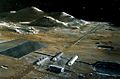 A Lunar base with a mass driver (the long structure that goes toward the horizon). NASA conceptual illustration
 An artist's conception of a "self-growing" robotic lunar factory.
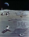 Microwave reflectors on the moon and teleoperated robotic paving rover and crane.
 "Crawler" traverses Lunar surface, smoothing, melting a top layer of regolith, then depositing elements of silicon PV cells directly on surface
 Sketch of the Lunar Crawler to be used for fabrication of lunar solar cells on the surface of the Moon.
 Shown here is an array of solar collectors that convert power into microwave beams directed toward Earth.
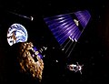 A solar power satellite built from a mined asteroid.


Counter arguments
Safety
The use of microwave transmission of power has been the most controversial issue in considering any SPS design. At the Earth's surface, a suggested microwave beam would have a maximum intensity at its center, of 23 mW/cm2 (less than 1/4 the solar irradiation constant), and an intensity of less than 1 mW/cm2 outside the rectenna fenceline (the receiver's perimeter). These compare with current United States Occupational Safety and Health Act (OSHA) workplace exposure limits for microwaves, which are 10 mW/cm2, - the limit itself being expressed in voluntary terms and ruled unenforceable for Federal OSHA enforcement purposes. A beam of this intensity is therefore at its center, of a similar magnitude to current safe workplace levels, even for long term or indefinite exposure. Outside the receiver, it is far less than the OSHA long-term levels] Over 95% of the beam energy will fall on the rectenna. The remaining microwave energy will be absorbed and dispersed well within standards currently imposed upon microwave emissions around the world. It is important for system efficiency that as much of the microwave radiation as possible be focused on the rectenna. Outside the rectenna, microwave intensities rapidly decrease, so nearby towns or other human activity should be completely unaffected.Exposure to the beam is able to be minimized in other ways. On the ground, physical access is controllable (e.g., via fencing), and typical aircraft flying through the beam provide passengers with a protective metal shell (i.e., a Faraday Cage), which will intercept the microwaves. Other aircraft (balloons, ultralight, etc.) can avoid exposure by observing airflight control spaces, as is currently done for military and other controlled airspace. The microwave beam intensity at ground level in the center of the beam would be designed and physically built into the system; simply, the transmitter would be too far away and too small to be able to increase the intensity to unsafe levels, even in principle.
In addition, a design constraint is that the microwave beam must not be so intense as to injure wildlife, particularly birds. Experiments with deliberate microwave irradiation at reasonable levels have failed to show negative effects even over multiple generations. Suggestions have been made to locate rectennas offshore, but this presents serious problems, including corrosion, mechanical stresses, and biological contamination.
A commonly proposed approach to ensuring fail-safe beam targeting is to use a retrodirective phased array antenna/rectenna. A "pilot" microwave beam emitted from the center of the rectenna on the ground establishes a phase front at the transmitting antenna. There, circuits in each of the antenna's subarrays compare the pilot beam's phase front with an internal clock phase to control the phase of the outgoing signal. This forces the transmitted beam to be centered precisely on the rectenna and to have a high degree of phase uniformity; if the pilot beam is lost for any reason (if the transmitting antenna is turned away from the rectenna, for example) the phase control value fails and the microwave power beam is automatically defocused. Such a system would be physically incapable of focusing its power beam anywhere that did not have a pilot beam transmitter. The long-term effects of beaming power through the ionosphere in the form of microwaves has yet to be studied, but nothing has been suggested which might lead to any significant effect.
Timeline
In the 20th century
- 1941: Isaac Asimov published the science fiction short story "Reason," in which a space station transmits energy collected from the sun to various planets using microwave beams.
- 1968: Dr. Peter Glaser introduces the concept of a "solar power satellite" system with square miles of solar collectors in high geosynchronous orbit for collection and conversion of sun's energy into a microwave beam to transmit usable energy to large receiving antennas (rectennas) on Earth for distribution.
- 1973: Dr. Peter Glaser is granted United States patent number 3,781,647 for his method of transmitting power over long distances using microwaves from a large (one square kilometer) antenna on the satellite to a much larger one on the ground, now known as a rectenna.
- 1978–81: The United States Department of Energy and NASA examine the solar power satellite (SPS) concept extensively, publishing design and feasibility studies.
- 1987: Stationary High Altitude Relay Platform a Canadian experiment
- 1995–97: NASA conducts a "Fresh Look" study of space solar power (SSP) concepts and technologies.
- 1998: The Space Solar Power Concept Definition Study (CDS) identifies credible, commercially viable SSP concepts, while pointing out technical and programmatic risks.
- 1998: Japan's space agency begins developing a Space Solar Power System (SSPS), a program that continues to the present day.[citation needed]
- 1999: NASA's Space Solar Power Exploratory Research and Technology program (SERT, see below) begins.
- 2000: John Mankins of NASA testifies in the U.S. House of Representatives, saying "Large-scale SSP is a very complex integrated system of systems that requires numerous significant advances in current technology and capabilities. A technology roadmap has been developed that lays out potential paths for achieving all needed advances — albeit over several decades.
In the 21st century
- 2001: NASDA (One of Japan's national space agencies before it became part of JAXA) announces plans to perform additional research and prototyping by launching an experimental satellite with 10 kilowatts and 1 megawatt of power.
- 2003: ESA studies
- 2007: The US Pentagon's National Security Space Office (NSSO) issues a report on October 10, 2007 stating they intend to collect solar energy from space for use on Earth to help the United States' ongoing relationship with the Middle East and the battle for oil. A demo plant could cost $10 billion, produce 10 megawatts, and become operational in 10 years.
- 2007: In May 2007 a workshop is held at the US Massachusetts Institute of Technology (MIT) to review the current state of the SBSP market and technology.
- 2010: Professors Andrea Massa and Giorgio Franceschetti announce a special session on the "Analysis of Electromagnetic Wireless Systems for Solar Power Transmission" at the 2010 Institute of Electrical and Electronics Engineers International Symposium on Antennas and Propagation.
- 2010: The Indian Space Research Organisation and US' National Space Society launched a joint forum to enhance partnership in harnessing solar energy through space-based solar collectors. Called the Kalam-NSS Initiative after the former Indian President Dr APJ Abdul Kalam, the forum will lay the groundwork for the space-based solar power program which could see other countries joining in as well.
- 2010: Sky's No Limit: Space-Based solar power, the next major step in the Indo-US strategic partnership?] written by USAF Lt Col Peter Garretson was published at the Institute for Defence Studies and Analysis.
- 2012: China proposed joint development between India and China towards developing a solar power satellite, during a visit by former Indian President Dr APJ Abdul Kalam.[92]
- 2015: JAXA announced on 12 March 2015 that they wirelessly beamed 1.8 kilowatts 50 meters to a small receiver by converting electricity to microwaves and then back to electricity.
- 2016: Lt Gen. Zhang Yulin, deputy chief of the [PLA] armament development department of the Central Military Commission, suggested that China would next begin to exploit Earth-Moon space for industrial development. The goal would be the construction of space-based solar power satellites that would beam energy back to Earth.
- 2016: A team with membership from the Naval Research Laboratory (NRL), Defense Advanced Projects Agency (DARPA), Air Force Air University, Joint Staff Logistics (J-4), Department of State, Makins Aerospace and Northrop Grumman won the Secretary of Defense (SECDEF) / Secretary of State (SECSTATE) / USAID Director's agency-wide D3 (Diplomacy, Development, Defense) Innovation Challenge with a proposal that the US must lead in space solar power. The proposal was followed by a vision video
- 2016: Citizens for Space-Based Solar Power has transformed the D3 proposal into active petitions on the White House Website "America Must Lead the Transition to Space-Based Energy"and Change.org "USA Must Lead the Transition to Space-Based Energy" along with the following video.
- 2016: Erik Larson and others from NOAA produce a paper "Global atmospheric response to emissions from a proposed reusable space launch system" The paper makes a case that up to 2 TW/year of power satellites could be constructed without intolerable damage to the atmosphere. Before this paper there was concern that the NOx produced by reentry would destroy too much ozone.
Non-typical configurations and architectural considerations
The typical reference system-of-systems involves a significant number (several thousand multi-gigawatt systems to service all or a significant portion of Earth's energy requirements) of individual satellites in GEO. The typical reference design for the individual satellite is in the 1-10 GW range and usually involves planar or concentrated solar photovoltics (PV) as the energy collector / conversion. The most typical transmission designs are in the 1–10 GHz (2.45 or 5.8 GHz) RF band where there are minimum losses in the atmosphere. Materials for the satellites are sourced from, and manufactured on Earth and expected to be transported to LEO via re-usable rocket launch, and transported between LEO and GEO via chemical or electrical propulsion. In summary, the architecture choices are:- Location = GEO
- Energy Collection = PV
- Satellite = Monolithic Structure
- Transmission = RF
- Materials & Manufacturing = Earth
- Installation = RLVs to LEO, Chemical to GEO
Alternate energy collection location: While GEO is most typical because of its advantages of nearness to Earth, simplified pointing and tracking, very small time in occultation, and scalability to meet all global demand several times over, other locations have been proposed:
- Sun Earth L1: Robert Kennedy III, Ken Roy & David Fields have proposed a variant of the L1 sunshade called "Dyson Dots" where a multi-terawatt primary collector would beam energy back to a series of LEO sun-synchronous receiver satellites. The much farther distance to Earth requires a correspondingly larger transmission aperture.
- Lunar Surface: Dr. David Criswell has proposed using the Lunar surface itself as the collection medium, beaming power to the ground via a series of microwave reflectors in Earth Orbit. The chief advantage of this approach would be the ability to manufacture the solar collectors in-situ without the energy cost and complexity of launch. Disadvantages include the much longer distance, requiring larger transmission systems, the required "overbuild" to deal with the lunar night, and the difficulty of sufficient manufacturing and pointing of reflector satellites.
- MEO: MEO systems have been proposed for in-space utilities and beam-power propulsion infrastructures. For example, see Royce Jones' paper.
- Highly Elliptical Orbits: Molniya, Tundra, or Quazi Zenith orbits have been proposed as early locations for niche markets, requiring less energy to access and providing good persistence.
- Sun-Sync LEO: In this near Polar Orbit, the satellites precess at a rate that allows them to always face the Sun as they rotate around Earth. This is an easy to access orbit requiring far less energy, and its proximity to Earth requires smaller (and therefore less massive) transmitting apertures. However disadvantages to this approach include having to constantly shift receiving stations, or storing energy for a burst transmission. This orbit is already crowded and has significant space debris.
- Equatorial LEO: Japan's SPS 2000 proposed an early demonstrator in equatorial LEO in which multiple equatorial participating nations could receive some power.
- Earth's Surface: Dr. Narayan Komerath has proposed a space power grid where excess energy from an existing grid or power plant on one side of the planet can be passed up to orbit, across to another satellite and down to receivers.
- Solar Thermal: Proponents of Solar Thermal have proposed using concentrated heating to cause a state change in a fluid to extract energy via rotating machinery followed by cooling in radiators. Advantages of this method might include overall system mass (disputed), non-degradation due to solar-wind damage, and radiation tolerance. One recent thermal solar power satellite design by Keith Henson has been visualized here.
- Solar Pumped Laser: Japan has pursued a solar-pumped laser, where sunlight directly excites the lasing medium used to create the coherent beam to Earth.
- Fusion Decay: This version of a power-satellite is not "solar". Rather, the vacuum of space is seen as a "feature not a bug" for traditional fusion. Per Dr. Paul Werbos, after fusion even neutral particles decay to charged particles which in a sufficiently large volume would allow direct conversion to current.
- Solar Wind Loop: Also called a Dyson–Harrop satellite satellite. Here the satellite makes use not of the photons from the Sun but rather the charged particles in the solar wind which via electro-magnetic coupling generate a current in a large loop.
- Direct Mirrors: Early concepts for direct mirror re-direction of light to planet Earth suffered from the problem that rays coming from the sun are not parallel but are expanding from a disk and so the size of the spot on the Earth is quite large. Dr. Lewis Fraas has explored an array of parbolic mirrors to augment existing solar arrays.[102]
- Swarms of Smaller Satellites: Some designs propose swarms of free-flying smaller satellites. This is the case with several laser designs, and appears to be the case with CALTECH's Flying Carpets. For RF designs, an engineering constraint is the sparse array problem.
- Free Floating Components: Solaren has proposed an alternative to the monolithic structure where the primary reflector and transmission reflector are free-flying.
- Spin Stabilization: NASA explored a spin-stabilized thin film concept.
- Photonic Laser Thruster (PLT) stabilized structure: Dr. Young Bae has proposed that photon pressure may substitute for compressive members in large structures.
- Laser: Lasers offer the advantage of much lower cost and mass to first power, however there is controversy regarding benefits of efficiency. Lasers allow for much smaller transmitting and receiving apertures. However, a highly concentrated beam has eye-safety, fire safety, and weaponization concerns. Proponents believe they have answers to all these concerns. A laser-based approach must also find alternate ways of coping with precipitation.
- Atmospheric Waveguide: Some have proposed it may be possible to use a short pulse laser to create an atmospheric waveguide through which concentrated microwaves could flow.
- Scalar: Some have even speculated it may be possible to transmit power through scalar waves.
- Lunar Materials: Designs exist for Solar Power Satellites that source >99% of materials from lunar regolith with very small inputs of "vitamins" from other locations. Using materials from the Moon is attractive because launch from the Moon is in theory far less complicated than from Earth. There is no atmosphere, and so components do not need to be packed tightly in an aeroshell and survive vibration, pressure and temperature loads. Launch may be via a magnetic mass driver and the requirement to use propellant for launch entirely. Launch from the Moon the GEO also requires far less energy than from Earth's much deeper gravity well. Building all the solar power satellites to fully supply all the required energy for the entire planet requires less than one millionth of the mass of the Moon.
- Self-Replication on the Moon: NASA explored a self-replicating factory on the Moon in 1980. More recently, Justin Lewis-Webber proposed a method of speciated manufacture of core elements based upon John Mankins SPS-Alpha design.
- Asteroidal Materials: Some asteroids are thought to have even lower Delta-V to recover materials than the Moon, and some particular materials of interest such as metals may be more concentrated or easier to access.
- In-Space/In-Situ Manufacturing: With the advent of in-space additive manufacturing, concepts such as SpiderFab might allow mass launch of raw materials for local extrusion.
- Lunar Chemical Launch: ULA has recently showcased a concept for a fully re-usable chemical lander XEUS to move materials from the Lunar surface to LLO or GEO.
- Lunar Mass Driver: Launch of materials from the lunar surface using a system similar to an aircraft carrier electromagnetic catapult. An unexplored compact alternative would be the slingatron.
- Lunar Space Elevator: An equatorial or near-equatorial cable extends to and through the lagrange point. This is claimed by proponents to be lower in mass than a traditional mass driver.
- Space Elevator: A ribbon of pure carbon nanotubes extends from its center of gravity in Geostationary orbit, allowing climbers to climb up to GEO. Problems with this include the material challenge of creating a ribbon of such length with adequate strength, management of collisions with satellites and space debris, and lightning.
- MEO Skyhook: As part of an AFRL study, Roger Lenard proposed a MEO Skyhook. It appears that a gravity gradient-stabilized tether with its center of mass in MEO can be constructed of available materials. The bottom of the skyhook is close to the atmosphere in a "non-keplerian orbit". A re-usable rocket can launch to match altitude and speed with the bottom of the tether which is in a non-keplerian orbit (travelling much slower than typical orbital speed). The payload is transferred and it climbs the cable. The cable itself is kept from de-orbiting via electric propusion and/or electromagnetic effects.
- MAGLEV Launch / StarTram: John Powell has a concept for a very high mass-flow system. In a first-gen system, built into a mountain, accelerates a payload through an evacuated MAGLEV track. A small on-board rocket circulizes the payload.
- Beamed Energy Launch: Kevin Parkin and Escape Dynamics both have concepts for ground-based irradiation of a mono-propellant launch vehicle using RF energy. The RF energy is absorbed and directly heats the propellant not unlike in NERVA-style nuclear-thermal. LaserMotive has a concept for a laser-based approach.
In fiction
Space stations transmitting solar power have appeared in science-fiction works like Isaac Asimov's "Reason" (1941), that centers around the troubles caused by the robots operating the station. Asimov's short story "The Last Question" also features the use of SBSP to provide limitless energy for use on Earth. Ben Bova's thriller PowerSat involves a billionaire bent on creating a solar powersat while others try to sabotage it.In the video game Sid Meier's Alpha Centauri, the player can construct a city improvement called an "Orbital Power Transmitter" which, while expensive, provides energy to all other cities. Constructing many of these results in huge bonuses to energy production for all cities the player owns. In the novel "Skyfall" (1976) by Harry Harrison an attempt to launch the core of powersat from Cape Canaveral ends in disaster when the launch vehicle fails trapping the payload in a decaying orbit. Several SimCity games have featured space-microwave power plants as buildable options for municipal energy, along with (unrealistic) disaster scenarios where the beam strays off the collector and sets fire to nearby areas. In the manga and anime Mobile Suit Gundam 00, an orbital ring containing multiple solar collectors and microwave transmitters, along with power stations and space elevators for carrying power back down to Earth's surface, are the primary source of electricity for the Earth in the 24th century.
Various aerospace companies have also showcased imaginative future solar power satellites in their corporate vision videos, including the Boeing You Just Wait, Lockheed Martin's The Next 100 Years, and United Launch Alliance CIS-Lunar 1000
XXX . V0 Attitude control
Attitude control is controlling the orientation of an object with respect to an inertial frame of reference or another entity (the celestial sphere, certain fields, nearby objects, etc.).
Controlling vehicle attitude requires sensors to measure vehicle orientation, actuators to apply the torques needed to re-orient the vehicle to a desired attitude, and algorithms to command the actuators based on (1) sensor measurements of the current attitude and (2) specification of a desired attitude. The integrated field that studies the combination of sensors, actuators and algorithms is called "Guidance, Navigation and Control" (GNC).
A spacecraft's attitude must typically be stabilized and controlled for a variety of reasons. It is oftentimes needed so that the spacecraft high-gain antenna may be accurately pointed to Earth for communications, so that onboard experiments may accomplish precise pointing for accurate collection and subsequent interpretation of data, so that the heating and cooling effects of sunlight and shadow may be used intelligently for thermal control, and also for guidance: short propulsive maneuvers must be executed in the right direction.
Types of stabilization
There are two principal approaches to stabilizing attitude control on spacecraft:- Spin stabilization is accomplished by setting the spacecraft spinning, using the gyroscopic action of the rotating spacecraft mass as the stabilizing mechanism. Propulsion system thrusters are fired only occasionally to make desired changes in spin rate, or in the spin-stabilized attitude. If desired, the spinning may be stopped through the use of thrusters or by yo-yo de-spin. The Pioneer 10 and Pioneer 11 probes in the outer solar system are examples of spin-stabilized spacecraft.
- Three-axis stabilization is an alternative method of spacecraft attitude control in which the spacecraft is held fixed in the desired orientation without any rotation.
- One method is to use small thrusters to continually nudge the spacecraft back and forth within a deadband of allowed attitude error. Thrusters may also be referred to as mass-expulsion control (MEC) systems, or reaction control systems (RCS). The space probes Voyager 1 and Voyager 2 employ this method, and have used up about three quarters of their 100 kg of propellant as of July 2015.
- Another method for achieving three-axis stabilization is to use electrically powered reaction wheels, also called momentum wheels, which are mounted on three orthogonal axes aboard the spacecraft. They provide a means to trade angular momentum back and forth between spacecraft and wheels. To rotate the vehicle on a given axis, the reaction wheel on that axis is accelerated in the opposite direction. To rotate the vehicle back, the wheel is slowed. Excess momentum that builds up in the system due to external torques from, for example, solar photon pressure or gravity gradients, must be occasionally removed from the system by applying controlled torque to the spacecraft to allowing the wheels to return to a desired speed under computer control. This is done during maneuvers called momentum desaturation or momentum unload maneuvers. Most spacecraft use a system of thrusters to apply the torque for desaturation maneuvers. A different approach was used by the Hubble Space Telescope, which had sensitive optics that could be contaminated by thruster exhaust, and instead used magnetic torquers for desaturation maneuvers.
Articulation
Many spacecraft have components that require articulation. Voyager and Galileo, for example, were designed with scan platforms for pointing optical instruments at their targets largely independently of spacecraft orientation. Many spacecraft, such as Mars orbiters, have solar panels that must track the Sun so they can provide electrical power to the spacecraft. Cassini's main engine nozzles are steerable. Knowing where to point a solar panel, or scan platform, or a nozzle — that is, how to articulate it — requires knowledge of the spacecraft's attitude. Because AACS keeps track of the spacecraft's attitude, the Sun's location, and Earth's location, it can compute the proper direction to point the appendages. It logically falls to one subsystem, then, to manage both attitude and articulation. The name AACS may even be carried over to a spacecraft even if it has no appendages to articulate.Geometry
Sensors
Relative attitude sensors
Many sensors generate outputs that reflect the rate of change in attitude. These require a known initial attitude, or external information to use them to determine attitude. Many of this class of sensor have some noise, leading to inaccuracies if not corrected by absolute attitude sensors.Gyroscopes
Gyroscopes are devices that sense rotation in three-dimensional space without reliance on the observation of external objects. Classically, a gyroscope consists of a spinning mass, but there are also "laser gyros" utilizing coherent light reflected around a closed path. Another type of "gyro" is a hemispherical resonator gyro where a crystal cup shaped like a wine glass can be driven into oscillation just as a wine glass "sings" as a finger is rubbed around its rim. The orientation of the oscillation is fixed in inertial space, so measuring the orientation of the oscillation relative to the spacecraft can be used to sense the motion of the spacecraft with respect to inertial space.[3]Motion reference units
Motion reference units are a kind of inertial measurement unit with single- or multi-axis motion sensors. They utilize MEMS gyroscopes. Some multi-axis MRUs are capable of measuring roll, pitch, yaw and heave. They have applications outside the aeronautical field, such as:- Antenna motion compensation and stabilization
- Dynamic positioning
- Heave compensation of offshore cranes
- High speed craft motion control and damping systems
- Hydro acoustic positioning
- Motion compensation of single and multibeam echosounders
- Ocean wave measurements
- Offshore structure motion monitoring
- Orientation and attitude measurements on Autonomous underwater vehicles and Remotely operated underwater vehicles
- Ship motion monitoring
Absolute attitude sensors
This class of sensors sense the position or orientation of fields, objects or other phenomena outside the spacecraft.Horizon sensor
A horizon sensor is an optical instrument that detects light from the 'limb' of Earth's atmosphere, i.e., at the horizon. Thermal infrared sensing is often used, which senses the comparative warmth of the atmosphere, compared to the much colder cosmic background. This sensor provides orientation with respect to Earth about two orthogonal axes. It tends to be less precise than sensors based on stellar observation. Sometimes referred to as an Earth sensor.[citation needed]Orbital gyrocompass
Similar to the way that a terrestrial gyrocompass uses a pendulum to sense local gravity and force its gyro into alignment with Earth's spin vector, and therefore point north, an orbital gyrocompass uses a horizon sensor to sense the direction to Earth's center, and a gyro to sense rotation about an axis normal to the orbit plane. Thus, the horizon sensor provides pitch and roll measurements, and the gyro provides yaw. See Tait-Bryan angles.Sun sensor
A sun sensor is a device that senses the direction to the Sun. This can be as simple as some solar cells and shades, or as complex as a steerable telescope, depending on mission requirements.Earth sensor
An Earth sensor is a device that senses the direction to Earth. It is usually an infrared camera; nowadays the main method to detect attitude is the star tracker, but Earth sensors are still integrated in satellites for their low cost and reliability.Star tracker
Star tracker

The STARS real-time star tracking software operates on an image from EBEX 2012, a high-altitude balloon-borne cosmology experiment launched from Antarctica on 2012-12-29
Magnetometer
A magnetometer is a device that senses magnetic field strength and, when used in a three-axis triad, magnetic field direction. As a spacecraft navigational aid, sensed field strength and direction is compared to a map of Earth's magnetic field stored in the memory of an on-board or ground-based guidance computer. If spacecraft position is known then attitude can be inferred.[citation needed]Algorithms
Control algorithms are computer programs that receive data from vehicle sensors and derive the appropriate commands to the actuators to rotate the vehicle to the desired attitude. The algorithms range from very simple, e.g. proportional control, to complex nonlinear estimators or many in-between types, depending on mission requirements. Typically, the attitude control algorithms are part of the software running on the hardware, which receives commands from the ground and formats vehicle data telemetry for transmission to a ground station.The attitude control algorithms are written and implemented based on requirement for a particular attitude maneuver. Asides the implementation of passive attitude control such as the gravity-gradient stabilization, most spacecrafts make use of active control which exhibits a typical attitude control loop. The design of the control algorithm depends on the actuator to be used for the specific attitude maneuver although using a simple proportional–integral–derivative controller (PID controller) satisfies most control needs.
The appropriate commands to the actuators are obtained based on error signals described as the difference between the measured and desired attitude. The error signals are commonly measured as euler angles (Φ, θ, Ψ), however an alternative to this could be described in terms of direction cosine matrix or error quaternions. The PID controller which is most common reacts to an error signal (deviation) based on attitude as follows

where is the control torque, is the attitude deviation signal, and are the PID controller parameters.


A simple implementation of this can be the application of the proportional control for nadir pointing making use of either momentum or reaction wheels as actuators. Based on the change in momentum of the wheels, the control law can be defined in 3-axes x, y, z as


This control algorithm also affects momentum dumping.
Another important and common control algorithm involves the concept of detumbling, which is attenuating the angular momentum of the spacecraft. The need to detumble the spacecraft arises from the uncontrollable state after release from the launch vehicle. Most spacecraft in low earth orbit (LEO) makes use of magnetic detumbling concept which utilizes the effect of the earth's magnetic field. The control algorithm is called the B-Dot controller and relies on magnetic coils or torque rods as control actuators. The control law is based on the measurement of the rate of change of body-fixed magnetometer signals.

where is the commanded magnetic dipole moment of the magnetic torquer and is the proportional gain and is the rate of change of the Earth's magnetic field.


Actuators
Attitude control can be obtained by several mechanisms, specifically:Thrusters
Reaction control system
Vernier thrusters are the most common actuators, as they may be used for station keeping as well. Thrusters must be organized as a system to provide stabilization about all three axes, and at least two thrusters are generally used in each axis to provide torque as a couple in order to prevent imparting a translation to the vehicle. Their limitations are fuel usage, engine wear, and cycles of the control valves. The fuel efficiency of an attitude control system is determined by its specific impulse (proportional to exhaust velocity) and the smallest torque impulse it can provide (which determines how often the thrusters must fire to provide precise control). Thrusters must be fired in one direction to start rotation, and again in the opposing direction if a new orientation is to be held. Thruster systems have been used on most manned space vehicles, including Vostok, Mercury, Gemini, Apollo, Soyuz, and the Space Shuttle.To minimize the fuel limitation on mission duration, auxiliary attitude control systems may be used to reduce vehicle rotation to lower levels, such as small ion thrusters that accelerate ionized gases electrically to extreme velocities, using power from solar cells.
Spin stabilization
The entire space vehicle itself can be spun up to stabilize the orientation of a single vehicle axis. This method is widely used to stabilize the final stage of a launch vehicle. The entire spacecraft and an attached solid rocket motor are spun up about the rocket's thrust axis, on a "spin table" oriented by the attitude control system of the lower stage on which the spin table is mounted. When final orbit is achieved, the satellite may be de-spun by various means, or left spinning. Spin stabilization of satellites is only applicable to those missions with a primary axis of orientation that need not change dramatically over the lifetime of the satellite and no need for extremely high precision pointing. It is also useful for missions with instruments that must scan the star field or Earth's surface or atmosphere. See spin-stabilized satellite.Momentum wheels
These are electric motor driven rotors made to spin in the direction opposite to that required to re-orient the vehicle. Because momentum wheels make up a small fraction of the spacecraft's mass and are computer controlled, they give precise control. Momentum wheels are generally suspended on magnetic bearings to avoid bearing friction and breakdown problems. To maintain orientation in three dimensional space a minimum of three must be used, with additional units providing single failure protection. See Euler angles.Control moment gyros
These are rotors spun at constant speed, mounted on gimbals to provide attitude control. Although a CMG provides control about the two axes orthogonal to the gyro spin axis, triaxial control still requires two units. A CMG is a bit more expensive in terms of cost and mass, because gimbals and their drive motors must be provided. The maximum torque (but not the maximum angular momentum change) exerted by a CMG is greater than for a momentum wheel, making it better suited to large spacecraft. A major drawback is the additional complexity, which increases the number of failure points. For this reason, the International Space Station uses a set of four CMGs to provide dual failure tolerance.Solar sails
Small solar sails (devices that produce thrust as a reaction force induced by reflecting incident light) may be used to make small attitude control and velocity adjustments. This application can save large amounts of fuel on a long-duration mission by producing control moments without fuel expenditure. For example, Mariner 10 adjusted its attitude using its solar cells and antennas as small solar sails.Gravity-gradient stabilization
In orbit, a spacecraft with one axis much longer than the other two will spontaneously orient so that its long axis points at the planet's center of mass. This system has the virtue of needing no active control system or expenditure of fuel. The effect is caused by a tidal force. The upper end of the vehicle feels less gravitational pull than the lower end. This provides a restoring torque whenever the long axis is not co-linear with the direction of gravity. Unless some means of damping is provided, the spacecraft will oscillate about the local vertical. Sometimes tethers are used to connect two parts of a satellite, to increase the stabilizing torque. A problem with such tethers is that meteoroids as small as a grain of sand can part them.Magnetic torquers
Coils or (on very small satellites) permanent magnets exert a moment against the local magnetic field. This method works only where there is a magnetic field against which to react. One classic field "coil" is actually in the form of a conductive tether in a planetary magnetic field. Such a conductive tether can also generate electrical power, at the expense of orbital decay. Conversely, by inducing a counter-current, using solar cell power, the orbit may be raised. Due to massive variability in Earth's magnetic field from an ideal radial field, control laws based on torques coupling to this field will be highly non-linear. Moreover, only two-axis control is available at any given time meaning that a vehicle reorient may be necessary to null all rates.Pure passive attitude control
There exist two main passive control types for satellites. The first one uses gravity gradient, and it leads to four stable states with the long axis (axis with smallest moment of inertia) pointing towards Earth. As this system has four stable states, if the satellite has a preferred orientation, e.g. a camera pointed at the planet, some way to flip the satellite and its tether end-for-end is needed. The other passive system orients the satellite along Earth's magnetic field thanks to a magnet.[7] These purely passive attitude control systems have limited pointing accuracy, because the spacecraft will oscillate around energy minima. This drawback is overcome by adding damper, which can be hysteretic materials or a viscous damper. The viscous damper is a small can or tank of fluid mounted in the spacecraft, possibly with internal baffles to increase internal friction. Friction within the damper will gradually convert oscillation energy into heat dissipated within the viscous damper.Reaction control system

Two of four Reaction Control System thruster quads on the Apollo Lunar Module
An RCS is capable of providing small amounts of thrust in any desired direction or combination of directions. An RCS is also capable of providing torque to allow control of rotation (roll, pitch, and yaw).
RCS systems often use combinations of large and small (vernier) thrusters, to allow different levels of response. Spacecraft reaction control systems are used:
- for attitude control during re-entry;
- for stationkeeping in orbit;
- for close maneuvering during docking procedures;
- for control of orientation, or 'pointing the nose' of the craft;
- as a backup means of deorbiting;
- as ullage motors to prime the fuel system for a main engine burn.
Location of thrusters on spacecraft
The Mercury space capsule and Gemini re-entry module both used groupings of nozzles to provide attitude control. The thrusters were located off their center of gravity, thus providing a torque to rotate the capsule. The Gemini capsule was also capable of adjusting its re-entry course by rolling, which directed its off-center lifting force. The Mercury thrusters used a hydrogen peroxide monopropellant which turned to steam when forced through a tungsten screen, and the Gemini thrusters used hypergolic mono-methyl hydrazine fuel oxidized with nitrogen tetroxide.
The Gemini spacecraft was also equipped with a hypergolic Orbit Attitude and Maneuvering System, which made it the first manned spacecraft with translation as well as rotation capability. In-orbit attitude control was achieved by firing pairs of eight 25-pound-force (110 N) thrusters located around the circumference of its adapter module at the extreme aft end. Lateral translation control was provided by four 100-pound-force (440 N) thrusters around the circumference at the forward end of the adaptor module (close to the spacecraft's center of mass). Two forward-pointing 85-pound-force (380 N) thrusters at the same location, provided aft translation, and two 100-pound-force (440 N) thrusters located in the aft end of the adapter module provided forward thrust, which could be used to change the craft's orbit.
The Apollo Command Module had a set of twelve hypergolic thrusters for attitude control, and directional re-entry control similar to Gemini.
The Apollo Service Module and Lunar Module each had a set of sixteen R-4D hypergolic thrusters, grouped into external clusters of four, to provide both translation and attitude control. The clusters were located near the craft's centers of gravity, and were fired in pairs in opposite directions for attitude control.
A pair of translation thrusters are located at the rear of the Soyuz spacecraft; the counter-acting thrusters are similarly paired in the middle of the spacecraft (near the center of mass) pointing outwards and forward. These act in pairs to prevent the spacecraft from rotating. The thrusters for the lateral directions are mounted close to the center of mass of the spacecraft, in pairs as well.
Location of thrusters on spaceplanes

Unlike these, the Space Shuttle Orbiter had many more thrusters, as it was required to carry out docking maneuvers in orbit. Shuttle thrusters were grouped in the nose of the vehicle and on each of the two aft Orbital Maneuvering System pods. No nozzles interrupted the heat shield on the underside of the craft; instead, the nose RCS nozzles which control positive pitch were mounted on the side of the vehicle, and were canted downward. The downward-facing negative pitch thrusters were located in the OMS pods mounted in the tail/afterbody.
Space station systems
The International Space Station uses electrically powered reaction control gyroscopes for primary attitude control, with RCS thruster systems as backup and augmentation systems.In human spaceflight, a life support system is a group of devices that allow a human being to survive in space. US government space agency NASA, and private spaceflight companies use the term environmental control and life support system or the acronym ECLSS when describing these systems for their human spaceflight missions. The life support system may supply air, water and food. It must also maintain the correct body temperature, an acceptable pressure on the body and deal with the body's waste products. Shielding against harmful external influences such as radiation and micro-meteorites may also be necessary. Components of the life support system are life-critical, and are designed and constructed using safety engineering techniques.
Human physiological and metabolic needs
A crewmember of typical size requires approximately 5 kg or 11.0231 lb(total) of food, water, and oxygen per day to perform the standard activities on a space mission, and outputs a similar amount in the form of waste solids, waste liquids, and carbon dioxide. The mass breakdown of these metabolic parameters is as follows: 0.84 kg of oxygen, 0.62 kg of food, and 3.52 kg of water consumed, converted through the body's physiological processes to 0.11 kg of solid wastes, 3.87 kg of liquid wastes, and 1.00 kg of carbon dioxide produced. These levels can vary due to activity level, specific to mission assignment, but will correlate to the principles of mass balance. Actual water use during space missions is typically double the specified values mainly due to non-biological use (i.e. personal cleanliness). Additionally, the volume and variety of waste products varies with mission duration to include hair, finger nails, skin flaking, and other biological wastes in missions exceeding one week in length. Other environmental considerations such as radiation, gravity, noise, vibration, and lighting also factor into human physiological response in space, though not with the more immediate effect that the metabolic parameters have.Atmosphere
Space life support systems maintain atmospheres composed, at a minimum, of oxygen, water vapor and carbon dioxide. The partial pressure of each component gas adds to the overall barometric pressure.By reducing or omitting diluents (constituents other than oxygen, e.g., nitrogen and argon) the total pressure can be lowered to a minimum of about 16 kPa. This can lighten spacecraft structures, reduce leaks and simplify the life support system.
However, the elimination of diluent gases substantially increases fire risks, especially in ground operations when for structural reasons the total cabin pressure must exceed the external atmospheric pressure; see Apollo 1. Furthermore, oxygen toxicity becomes a factor at high oxygen concentrations. For this reason, most modern crewed spacecraft use conventional air (nitrogen/oxygen) atmospheres and use pure oxygen only in pressure suits during extravehicular activity where acceptable suit flexibility mandates the lowest inflation pressure possible
Water
Water is consumed by crew members for drinking, cleaning activities, EVA thermal control, and emergency uses. It must be stored, used, and reclaimed (from waste water) efficiently since no on-site sources currently exist for the environments reached in the course of human space exploration. Future lunar missions may utilise water sourced from polar ices; Mars missions may utilise water from the atmosphere or ice deposits.Food
All space missions to date have used supplied food. Life support systems could include a plant cultivation system which allows food to be grown within buildings and/or vessels. This would also regenerate water and oxygen. However, no such system has flown in space as yet. Such a system could be designed so that it reuses most (otherwise lost) nutrients. This is done, for example, by composting toilets which reintegrate waste material (excrement) back into the system, allowing the nutrients to be taken up by the food crops. The food coming from the crops is then consumed again by the system's users and the cycle continues.Microbe detection and control
The NASA LOCAD (Lab-on-a-Chip Applications Development) project is working on systems to help detect bacterial and fungal growths in spacecraft used for long-duration spaceflight.Space Shuttle
The Space Shuttle was the first American spacecraft to have an Earth-like atmospheric mixture, comprising 22% oxygen and 78% nitrogen. For the Space Shuttle, NASA includes in the ECLSS category systems that provide both life support for the crew and environmental control for payloads. The Shuttle Reference Manual contains ECLSS sections on: Crew Compartment Cabin Pressurization, Cabin Air Revitalization, Water Coolant Loop System, Active Thermal Control System, Supply and Waste Water, Waste Collection System, Waste Water Tank, Airlock Support, Extravehicular Mobility Units, Crew Altitude Protection System, and Radioisotope Thermoelectric Generator Cooling and Gaseous Nitrogen Purge for PayloadsSpace station systems include technology that enables humans to live in space for a prolonged period of time. Such technology includes filtration systems for human waste disposal and air production.
XXX . V000 Directional stability
Directional stability is stability of a moving body or vehicle about an axis which is perpendicular to its direction of motion. Stability of a vehicle concerns itself with the tendency of a vehicle to return to its original direction in relation to the oncoming medium (water, air, road surface, etc.) when disturbed (rotated) away from that original direction. If a vehicle is directionally stable, a restoring moment is produced which is in a direction opposite to the rotational disturbance. This "pushes" the vehicle (in rotation) so as to return it to the original orientation, thus tending to keep the vehicle oriented in the original direction.
Directional stability is frequently called "weather vaning" because a directionally stable vehicle free to rotate about its center of mass is similar to a weather vane rotating about its (vertical) pivot.
With the exception of spacecraft, vehicles generally have a recognisable front and rear and are designed so that the front points more or less in the direction of motion. Without this stability, they may tumble end over end, spin or orient themselves at a high angle of attack, even broadside on to the direction of motion. At high angles of attack, drag forces may become excessive, the vehicle may be impossible to control, or may even experience structural failure. In general, land, sea, air and underwater vehicles are designed to have a natural tendency to point in the direction of motion.
Example: road vehicle
Arrows, darts, rockets, and airships have tail surfaces to achieve stability. A road vehicle does not have elements specifically designed to maintain stability, but relies primarily on the distribution of mass.Introduction
These points are best illustrated with an example which is familiar to most readers - the humble motor car.The first stage of studying the stability of a road vehicle is the derivation of a reasonable approximation to the equations of motion.

The diagram illustrates a four-wheel vehicle, in which the front axle is located a metres ahead of the centre of gravity and the rear axle is b metres aft of the cg. The body of the car is pointing in a direction (theta) whilst it is travelling in a direction (psi). In general, these are not the same. The tyre treads at the region of contact point in the direction of travel, but the hubs are aligned with the vehicle body, with the steering held central. The tyres distort as they rotate to accommodate this mis-alignment, and generate side forces as a consequence.


The net side force Y on the vehicle is the centripetal force causing the vehicle to change the direction it is traveling:


Stability analysis
We do not need to solve the equation of motion explicitly to decide whether the solution diverges indefinitely or converges to zero following an initial perturbation. The form of the solution depends on the signs of the coefficients.The coefficient of will be called the 'damping' by analogy with a mass-spring-damper which has a similar equation of motion.

By the same analogy, the coefficient of will be called the 'stiffness', as its function is to return the system to zero deflection, in the same manner as a spring.
The form of the solution depends only on the signs of the damping and stiffness terms. The four possible solution types are presented in the figure.

The only satisfactory solution requires both stiffness and damping to be positive.
The damping term is:

The stiffness term is:


Relative effect of front and rear tyres
If for some reason (incorrect inflation pressure, worn tread) the tyres on one axle are incapable of generating significant lateral force, the stability will obviously be affected. Assume to begin with that the rear tyres are faulty, what is the effect on stability?If the rear tyres produce no significant forces, the side force and yawing moment become:


It follows that the condition of the rear tyres is more critical to directional stability than the state of the front tyres. Also, locking the rear wheels by applying the handbrake, renders the vehicle directionally unstable, causing it to spin. Since the vehicle is not under control during the spin, the 'handbrake turn' is usually illegal on public roads.
Steering forces
Deflecting the steering changes the slip angle of the front tyres, generating a sideforce. With conventional steering, the tyres are deflected by different amounts, but for the purposes of this analysis, the additional slip will be considered equal for both front tyres.The side force becomes:


As an example:
-
- with k=10kN/radian, M=1000kg, b=1.0m, a=1.0m, the vehicle understeers below 11.3mph.
Note: Installing a heavy, powerful engine in a light weight production vehicle designed around a small engine increases both its directional stability, and its tendency to understeer. The result is an overpowered vehicle with poor cornering performance.
Even worse is the installation of an oversized power unit into a rear engined production vehicle without corresponding modification of suspension or mass distribution, as the result will be directionally unstable at high speed.
Limitations of the analysis
The forces arising from slip depend on the loading on the tyre as well as the slip angle, this effect has been ignored, but could be taken into account by assuming different values of k for the front and rear axles. Roll motion due to cornering will redistribute the tyre loads between the nearside and offside of the vehicle, again modifying the tyre forces. Engine torque likewise re-distributes the load between front and rear tyres.A full analysis should also take account of the suspension response.
XXX . V0000 Relaxed stability
In aviation, relaxed stability is the tendency of an aircraft to change its attitude and angle of bank of its own accord. An aircraft with relaxed stability will oscillate in simple harmonic motion around a particular attitude at an increasing amplitude.
This can be contrasted with the behaviour of an aircraft with positive stability, which, when trimmed to fly at a certain attitude, will continue to do so in the absence of control input, and if perturbed will oscillate in simple harmonic motion on a decreasing scale around and eventually return to the trimmed attitude. A positively stable aircraft will also resist any bank movement. A Cessna 152 is an example of a stable aircraft. Similarly, an aircraft with neutral stability will not return to its trimmed setting without control input, but will oscillate in a stable simple harmonic motion around the trimmed setting continuously, neither increasing nor decreasing oscillation amplitude, and be susceptible to bank influences .
Early aircraft
Early attempts at heavier-than-air flight were marked by a differing concept of stability than is used today. Most aeronautical investigators regarded flight as if it were not so different from surface locomotion, except the surface was elevated. They thought of changing direction in terms of a ship's rudder, so the flying machine would remain essentially level in the air, as did an automobile or a ship at the surface. The idea of deliberately leaning, or rolling, to one side either seemed undesirable or did not enter their thinking.Some of these early investigators, including Langley, Chanute, and later Santos-Dumont and the Voisin brothers, sought the ideal of 'inherent stability' in a very strong sense, believing a flying machine should be built to automatically roll to a horizontal (lateral) position after any disturbance. They achieved this with the help of Hargrave cellular wings (wings with a box kite structure, including the vertical panels) and strongly dihedral wings. In most cases they did not include any means for a pilot to control the aircraft roll[2][page needed] — they could only control elevator and rudder. The unpredicted effect of this was that it was very hard to turn the aircraft without rolling. They were also strongly affected by side gusts and side winds upon landing.
The Wright brothers designed their 1903 first powered Flyer with anhedral (drooping) wings, which are inherently unstable. They showed that a pilot can maintain control of lateral roll and it was a good way for a flying machine to turn—to "bank" or "lean" into the turn just like a bird or just like a person riding a bicycle. Equally important, this method would enable recovery when the wind tilted the machine to one side. Although used in 1903, it would not become widely known in Europe until August 1908, when Wilbur Wright demonstrated to European aviators the importance of the coordinated use of elevator, rudder and roll control for making effective turns.
Vertical wing position
The vertical positioning of the wing changes the roll stability of an aircraft.- An aircraft with a "high" wing position (i.e., set on top of the fuselage) has a higher roll stability. For example, the Cessna 152.
- An aircraft with a "low" wing (i.e., underneath the fuselage) has less roll stability. The Piper Pawnee uses a "low" wing.
Unstable aircraft
Modern military aircraft, particularly low observable ("stealth") designs, often exhibit instability as a result of their shape. The Lockheed F-117 Nighthawk, for instance, employs a highly non-traditional fuselage and wing shape in order to reduce its radar cross section and enable it to penetrate air defenses with relative impunity. However, the flat facets of the design reduce its stability to the point where a computerized fly-by-wire system was required to allow safe operation.Relaxed stability designs are not limited to military jets. The McDonnell Douglas MD-11 has a relaxed stability design which was implemented to save fuel. To ensure stability for safe flight, an LSAS (Longitudinal Stability Augmentation System) was introduced to compensate for the MD-11's rather short horizontal stabilizer and ensure that the aircraft would remain stable. However, there have been incidents in which the MD-11's relaxed stability caused an "inflight upset."
Intentional instability

The Lockheed F-117 Nighthawk is not an inherently stable design.
A less stable aircraft requires smaller control deflections to initiate maneuvering; consequently drag and control surface imposed stresses will be reduced and aircraft responsiveness will be enhanced. Since these characteristics will typically make control by the pilot difficult or impossible, an artificial stability will typically be imposed using computers, servos, and sensors as parts of a fly by wire control system.
Flight dynamics
Flight dynamics is the study of the performance, stability, and control of vehicles flying through the air or in outer space. It is concerned with how forces acting on the vehicle influence its speed and attitude with respect to time.
In fixed-wing aircraft, the changing orientation of the vehicle with respect to the local air flow is represented by two critical parameters, angle of attack ("alpha") and angle of sideslip ("beta"). These angles describe the vector direction of airspeed, important because they are the principal source of modulations in the aerodynamic forces and moments applied to the aircraft.
Spacecraft flight dynamics involve three forces: propulsive (rocket engine), gravitational, and lift and drag (when traveling through the earth's or any other atmosphere). Because aerodynamic forces involved with spacecraft flight are very small, this leaves gravity as the dominant force.
Aircraft and spacecraft share a critical interest in their orientation with respect to the earth horizon and heading, and this is represented by another set of angles, "yaw", "pitch", and "roll", which angles match their colloquial meaning, but also have formal definition as an Euler sequence. These angles are the product of the rotational equations of motion, where orientation responds to torque, just as the velocity of a vehicle responds to forces. For all flight vehicles, these two sets of dynamics, rotational and translational, operate simultaneously and in a coupled fashion to evolve the vehicle's state (orientation and velocity) trajectory.
Aircraft

- This section focuses on fixed-wing aircraft. For other kinds see aircraft.
Aircraft engineers develop control systems for a vehicle's orientation (attitude) about its center of mass. The control systems include actuators, which exert forces in various directions, and generate rotational forces or moments about the center of gravity of the aircraft, and thus rotate the aircraft in pitch, roll, or yaw. For example, a pitching moment is a vertical force applied at a distance forward or aft from the center of gravity of the aircraft, causing the aircraft to pitch up or down.
Roll, pitch and yaw refer, in this context, to rotations about the respective axes starting from a defined equilibrium state. The equilibrium roll angle is known as wings level or zero bank angle, equivalent to a level heeling angle on a ship. Yaw is known as "heading".
A fixed-wing aircraft increases or decreases the lift generated by the wings when it pitches nose up or down by increasing or decreasing the angle of attack (AOA). The roll angle is also known as bank angle on a fixed-wing aircraft, which usually "banks" to change the horizontal direction of flight. An aircraft is usually streamlined from nose to tail to reduce drag making it typically advantageous to keep the sideslip angle near zero, though there are instances when an aircraft may be deliberately "sideslipped" for example a slip in a fixed-wing aircraft.
Spacecraft and satellites
The forces acting on spacecraft are of three types: propulsive force (usually provided by the vehicle's engine thrust); gravitational force exerted by the Earth and other celestial bodies; and aerodynamic lift and drag (when flying in the atmosphere of the Earth or another body, such as Mars or Venus). The vehicle's attitude must be taken into account because of its effect on the aerodynamic and propulsive forces.[6] There are other reasons, unrelated to flight dynamics, for controlling the vehicle's attitude in non-powered flight (e.g., thermal control, solar power generation, communications, or astronomical observation).
The flight dynamics of spacecraft differ from those of aircraft in that the aerodynamic forces are of very small, or vanishingly small effect for most of the vehicle's flight, and cannot be used for attitude control during that time. Also, most of a spacecraft's flight time is usually unpowered, leaving gravity as the dominant force.
XXX . V00000 The debate about the relative merits of exploring space with humans and robots is as old as the space program itself
There are five arguments that are advanced in any discussion about the utility of space exploration and the roles of humans and robots. Those arguments, in roughly ascending order of advocate support, are the following:
1. Space exploration will eventually allow us to establish a human civilization on another world (e.g., Mars) as a hedge against the type of catastrophe that wiped out the dinosaurs.
2. We explore space and create important new technologies to advance our economy. It is true that, for every dollar we spend on the space program, the U.S. economy receives about $8 of economic benefit. Space exploration can also serve as a stimulus for children to enter the fields of science and engineering.
3. Space exploration in an international context offers a peaceful cooperative venue that is a valuable alternative to nation state hostilities. One can look at the International Space Station and marvel that the former Soviet Union and the U.S. are now active partners. International cooperation is also a way to reduce costs.
4. National prestige requires that the U.S. continue to be a leader in space, and that includes human exploration. History tells us that great civilizations dare not abandon exploration.
5. Exploration of space will provide humanity with an answer to the most fundamental questions: Are we alone? Are there other forms of life beside those on Earth?
The human spirit seeks to discover the unknown, and in the process explore the physical and psychological potential of human endurance.
There have always been the few risk-takers who ventured for the rest of us to follow. Because of earlier pioneers, air travel is now commonplace, and space travel for all is just around the corner. Economic and societal benefits are not immediately evident, but they always follow, as does our understanding of human potential to overcome challenges. Fifty years after Sputnik, space remains the next frontier.
Without risking human lives, robotic technology such as unmanned missions, probes, observatories, and landers enables space exploration. It lays the groundwork, and does the scouting.
“only a human can experience what being in space feels like, and only a human can communicate this to others.” It is humans who repair the Hubble telescope. It is humans who service the International Space Station (ISS). Mercury astronauts were the first to photograph Earth from space with hand-held cameras. Earth scientists in orbit on the ISS may view aspects of global change that only a trained eye can see. In addition, studying astronauts in the microgravity of space has been the only means of understanding how gravity affects human development and health here on Earth. It is highly probable that, in this century, humans will settle on other planets. Our ability to explore and sustain human presence there will not only expand Earth’s access to mineral resources but, should the need arise, provide alternative habitats for humanity’s survival.
At what cost? Is there a price to inspiration and creativity? Economic, scientific and technological returns of space exploration have far exceeded the investment. Globally, 43 countries now have their own observing or communication satellites in Earth orbit. Observing Earth has provided G.P.S., meteorological forecasts, predictions and management of hurricanes and other natural disasters, and global monitoring of the environment, as well as surveillance and intelligence. Satellite communications have changed life and business practices with computer operations, cell phones, global banking, and TV. Studying humans living in the microgravity of space has expanded our understanding of osteoporosis and balance disorders, and has led to new treatments. Wealth-generating medical devices and instrumentation such as digital mammography and outpatient breast biopsy procedures and the application of telemedicine to emergency care are but a few of the social and economic benefits of manned exploration that we take for granted.
Space exploration is not a drain on the economy; it generates infinitely more than wealth than it spends. Royalties on NASA patents and licenses currently go directly to the U.S. Treasury, not back to NASA. I firmly believe that the Life Sciences Research Program would be self-supporting if permitted to receive the return on its investment. NASA has done so much with so little that it has generally been assumed to have had a huge budget. In fact, the 2007 NASA budget of $16.3 billion is a minute fraction of the $13 trillion total G.D.P.
“What’s the hurry?” is a legitimate question. As the late Senator William Proxmire said many years ago, “Mars isn’t going anywhere.” Why should we commit hard-pressed budgets for space exploration when there will always be competing interests? However, as Mercury, Gemini and Apollo did 50 years ago, our future scientific and technological leadership depends on exciting creativity in the younger generations. Nothing does this better than manned space exploration. There is now a national urgency to direct the creative interests of our youth towards careers in science and engineering. We need to keep the flame of manned space exploration alive as China, Russia, India, and other countries forge ahead with substantial investments that challenge U.S. leadership in space.

XXX . V000000 Satellite Technologies
The surprise launch of Russia's Sputnik, the world’s first artificial satellite, in 1957 prompted an explosion of interest in the possibilities of satellite technology. Apart from the military implications of its possible development as a weapons platform it also alerted engineers to the potential of using the technology for peaceful applications including the possibility that Arthur C. Clarke's dream of world-wide communications based on Geostationary Satellites might at last be realised. But first some technical issues had to be resolved.
Travelling at 18,000 mph (29,000 kph or 8,100 m/s), it circled the Earth once every 96.2 minutes emitting beeping radio signals from its near omnidirectional antennas at as it went. It served no useful purpose, but was a spectacular demonstration of the Soviet capability in space. |

The Challenges (Old and New)
A satellite communications link provides "line of sight" transmission of signals between a transmitter and a remote receiver or receivers on the ground via a transponder mounted in a satellite orbiting high above the Earth such that it can be seen by both the transmitter and the receiver. Creating such a link required mastering a series of technologies which were new and radical at the time. Space was an unknown frontier. Satellites had to be placed into a precisely controlled orbits. Once in place there was no possibility of maintenance. Rocket power, guidance and control were still in their infancy when this new communications revolution was launched. Some of the relevant technologies are outlined and explained here.
Orbits and Communications
A Geostationary Earth Orbit (GEO) is an orbit in which the position in sky of the orbiting object remains the same so that it appears motionless to a stationary observer on Earth. To achieve this, the orbit needs to be circular and stationed directly over the equator, with an orbital period equal to the Earth's rotational period of one sidereal day and following the direction as the earth's rotation at an altitude of 22,236.47 miles (35,786.13 kms) above the Earth.The Moon, at an altitude of 240,000 miles (386,000 kms) takes a month to orbit the Earth
The velocity of a satellite orbiting at this altitude is 6,877.82 mph (11,068.78.kph) and this velocity must be precisely maintained for the satellite to appear geostationary. (A sidereal day is the time scale based on the Earth's rate of rotation measured relative to the fixed stars and is equal to 23 hours, 56 minutes and 4.0916 seconds).
A Geosynchronous Orbit is also an orbit with the same period as Earth's rotation, in other words it is synchronous with Earth's rotation, but the plane of the orbit can have any inclination between 0 and 90 degrees with respect to the equatorial plane and the orbit may be elliptical rather than circular. To an observer on the ground the orbiting object appears to move North and South in the sky in an elongated 'figure of eight' centred on a fixed longitude, following the same trajectory every day and passing any particular point at exactly the same time every day. A steerable antenna may be required to maintain acceptable communications at the limits of these apparent oscillations.
For satellite communications the advantage of the geostationary orbit is that the satellite can be accessed by means of a fixed antenna and it does not need a large steerable antenna on the ground to track the satellite for optimum signal reception. In addition, because of the very high altitude of their orbits, geostationary satellites may have a very wide signal footprint covering up to 42% of the Earth's surface, with the potential to provide "line of sight" communications across oceans and between continents. In practical systems, reliable communications are not possible at the limits of this footprint but a single geostationary satellite can however provide continuous service, which can be accessed by fixed antennas, to subscribers in up to 34% of the Earth's surface. Thus they are ideal for providing low cost television broadcasting services as well as for monitoring the environment and the weather.
Disadvantages compared with Low Earth Orbit (LEO) satellites are that orbiting at a higher altitude, they need more powerful launch vehicles to put them in place and the communications system needs higher power transmitters and more sensitive receivers because of the increased path loss. Geostationary satellites also have poor signal coverage in the polar regions. See Look Angles which explains why.
For simplicity, the satellite should be launched into a geostationary orbit directly from a launch site on the equator but this is not always possible. In such cases when the satellite is launched from sites in higher latitudes, assuming it is launched at synchronous speed, it will enter a geosynchronous and possibly elliptical orbit because of the inclination of the plane of the orbit. Further orbital manoeuvres will be required to move the satellite into a geostationary orbit.
Since there must be a reasonable space between satellites to avoid collisions but more importantly to avoid harmful radio-frequency interference during operations there can only be a limited number of orbital "slots" available for GEO satellites and there are hundreds of commercial and government satellites vying for allocation of these slots and the frequency allocations that go with them.
Low Earth Orbit (LEO) satellites can be launched directly into the desired orbits and don't need the complex orbital manoeuvres required by GEO satellites to place them in position. They also require less energy to place them into orbit and they can use less powerful amplifiers for successful transmission of communications. However the potential atmospheric drag, limits the lowest practical orbital altitude to about 180 miles (300 km)
Because of their lower orbits, LEO satellites are able to distinguish details of the Earth's surface much more clearly as they are not so far away so they are ideal Earth observation, remote sensing and surveillance. For the same reason, the two way signal transmission delay is much lower than the transmission delay in GEO systems at only 4 to 8 milliseconds per hop depending on the position of the satellite.
LEO satellites however must travel at a much higher angular speeds to remain in orbit since they need a greater centrifugal force to balance the higher gravitational force experienced at the lower altitude. Thus they are non-geosynchronous and will orbit the earth several times per day. Communications will therefore be intermittent since the satellites will only be visible to observers on the ground for short period each time they pass overhead. Tracking such fast moving satellites also requires highly manoeuvrable light weight antennas, and many of them, to provide wide area radio coverage.
Another problem with communications satellites in orbits lower than geosynchronous is that a greater number of satellites are required to sustain uninterrupted transmissions. Whereas a single GEO satellite can cover 34 percent of Earth's surface, individual LEO and MEO satellites cover only between 2 and 20 percent. This means that a fleet of satellites, known as a "constellation", is required to provide a global communications network with continuous coverage.
Because of their relative simplicity and lower cost, LEO satellites are still used for many communications applications. Satellite telephone systems such as Iridium use LEO satellites because their lower orbits permit the use of relatively low power, low sensitivity telephone handsets.
The International Space Station (ISS) and the Hubble telescope are both in LEO orbits, the ISS at 260 miles (420 kms) and Hubble at 347 miles (559 kms).
Medium Earth Orbits (MEO) range in altitude from 1,200 miles (2,000 kms) up to the geosynchronous orbit at 22,236 miles (35,786 kms) which includes part of the lower and all of the upper Van Allen radiation belts. Practical orbits therefore avoid these regions.
As with all satellites in non-geosynchronous orbits, MEO satellites are only visible intermittently by observers on the ground. The higher the orbit, the greater the footprint.
Typical MEO applications are navigation, communications, and geodetic / space environment science.
The most common altitude is just above the upper Van Allen belt at around 12,552 miles (20,200 kilometres), which yields an orbital period of 12 hours, and is used for many national navigation systems such as the U.S. the Global Positioning System (GPS).
Mobile voice communications tend to occupy orbits below the upper Van Allen belt at altitudes below 8000 miles (13,000 kms)
Highly Elliptical Orbits (HEO)
HEO orbits, first proposed by British engineer Bill Hilton, allow the satellite footprint to be concentrated on specific regions of the Earth. The orbit of the Russian Molniya satellites for example which provide telephony and TV services over Russia is designed so that each satellite spends the great majority of its time over the far northern latitudes. With a period of 12 hours the satellite is available for operation over the targeted region for eight hours every second revolution. In this way a constellation of three Molniya satellites, plus one spare, can provide uninterrupted coverage.
Molniya Orbit
Molniya Satellite Ground Track
Public Domain
The Molniya Orbit
Signal levels received from geostationary satellites diminish the further the distance the ground stations are from the equator so that communications to high latitude regions by geostationary satellites may be difficult or impossible. (See Look Angles for an explanation)
To provide acceptable signal coverage in high latitudes such as Canada and Russia whose land masses are mostly between latitudes of 50 and 70 degrees North requires very high satellite transmitter powers or alternative satellite orbits which place the satellite directly over the country.
The Highly Elliptical Orbit (HEO) specified for Russia's Molniya satellite, now called the Molniya Orbit, was designed to provide this second solution.
The Molniya orbit was inclined at 63.4 degrees to the equator and semi-synchronous making a complete revolution of the Earth every 12 hours synchronised with the Earth's rotation. Its perigee in the southern hemisphere was around 310miles (500 kms) and its apogee in the northern hemisphere was around 24,850 miles (40,000 kms).
In practice this means that the satellite makes two orbits per day during each of which it moves North and South speeding very quickly through its perigee over the oceans of the southern hemisphere, but slowly hovering around its apogee over the northern hemisphere obeying Kepler's Second Law (Law of Equal Areas) for its highly elliptical orbit. During this time however the Earth is rotating, so the satellite as seen from the Earth appears to be moving eastwards. On the first 12 hour orbit the satellite hovers for about eight hours over Canada and the USA and during the following orbit it hovers for eight hours over Russia. See the Molniya Ground Track diagram opposite.
Some would say that this allows the satellite to spy on the USA during the day and to download the information gathered to Russia during the night, but there's nothing to stop Americans doing something similar.
Molniya's main purpose however was to provide television and telephony services across Russia and into the Arctic polar region. Its high apogee enables it to provide wide coverage with a single antenna but a disadvantage of the Molniya orbit is that it is not geostationary so steerable antennas were required to send and receive the signals however this is mitigated somewhat by Molniya's slow speed through the apogee which puts less demand on the ground station antenna positioning systems. Twenty four hour continuous national coverage could be provided to a network of ground stations by three satellites each spending eight hours over the country. This was at least better than the option of using a larger constellation of LEO satellites which needed fast acting steerable antennas to follow them.
Molniya orbits also had the advantage of requiring less rocket power to launch the satellite into the HEO orbit than to get it into a geostationary orbit.
Polar Orbits
Satellites in these orbits fly over the Earth from pole to pole in an orbit perpendicular to the equatorial plane. This orbit is most commonly used in surface mapping and observation satellites since it allows the orbiting satellite to take advantage of the earth's rotation below to observe the entire surface of the Earth as it passes below. Many of the pictures of the Earth's surface in applications such as Google Earth come from satellites in polar orbits.
Orbital Mathematics
When a moving satellite, natural or artificial, enters the gravitational field of a very large object such as a planet or star, its momentum will keep it moving and in the vacuum of space there will be no drag to slow it down so it will keep moving at the same velocity. Its direction will however change due to the influence of the gravitational field causing its path to curve towards the large object. When the centrifugal force acting on the satellite, due to the tangential velocity of its curved path, just matches the gravitational pull of the large object the satellite will enter a stable orbit around the larger object. If the velocity is too low, the satellite will fall into the large object. If it is too high, it will fly off into space.Kepler's Laws
Orbital Manoeuvres
Parking Orbit


The Centrifugal force Fc acting on a body or satellite in angular motion is given by:
Fc = mv2/r = mrω2
where:m is the mass of the satellite
r is the distance between the centre of motion (the Earth) and the centre of the satellite
v is the tangential velocity of the satellite
ω is the angular velocity of the satellite
The Gravitational force Fg acting between two bodies, one of which is the Earth, is given by:
Fg = GMm/r2
where:
G is the universal gravitational constantM is the mass of the Earth
m is the mass of the satellite
r is the distance between the centres of the masses
When a satellite is in a steady orbit aroung the Earth, the centrifugal force actiing on it just balances the gravittational force acting on it. This occurs when:
mv2/r = GMm/r2
The equations describing the satellite's speed and orbital period are derived from this relationship.
Kepler's First Law (Law of Orbits) All planets move in elliptical orbits, with the Sun at one focus. See diagram opposite Kepler's Second Law (Law of Areas) The line between a planet and the Sun sweeps out equal areas in equal times as the planet travels around its elliptical orbit. See diagram opposite |

T = 2π√ (r3 / GM)
Where r is the semi-major axis or radius of the orbit
When the mass of the orbiting body is negligible compared to the mass of the Earth, the orbital speed Vo is given by:
Vo ≈ √(GM / r)
Where r is the distance between the centre of the masses of the Earth and the satellite In other words: The higher the altitude, the longer the orbital period and the slower the orbital speed.

It is not always possible to launch a space vehicle directly into its desired orbit. The launch site may be in an inconvenient location with respect to the orbit or the launch window may be very short, a few minutes or even seconds. In such cases the vehicle may be launched into a temporary orbit called a parking orbit which provides more options for realising the ultimate orbit.
Using a parking orbit can extend the launch window by several hours by increasing the possible range of locations from which to initiate the next propulsion stage. It also enables the spacecraft to reach a higher perigee by firing the second stage after it has reached a higher point in the parking orbit which will raise its perigee in the new orbit.
For manned space missions the parking orbit provides an opportunity to check that all systems are working satisfactorily before proceeding to the next critical stage.
Transfer Orbit
The transfer orbit is the orbit used to break out of the parking orbit and break into the geosynchronous or geostationary orbit. The notion of using an elliptical orbit to transfer between two circular orbits in the same plane but with different altitudes was originally conceived by German scientist Walter Hohmann in 1925 and published in his book Die Erreichbarkeit der Himmelskörper (The Accessibility of Celestial Bodies) and the manoeuvre was subsequently named for him.
The Hohmann transfer uses two rocket engine impulses, one to move the spacecraft onto the transfer orbit and a second to move off it into a new orbit. The first impulse increases the speed and energy of the spacecraft propelling it into a larger elliptical orbit with its apogee lying on the desired new orbit. The second impulse takes place at the apogee and accelerates the spacecraft once more this time widening the new orbit into a circular path. It does not involve any changes in the plane of the orbit.
The inclination of the transfer orbit is the angle between the spacecraft's orbit plane and the Earth's equatorial plane and is determined by the latitude of the launch site and the launch azimuth (direction).To obtain a geostationary orbit the inclination and eccentricity must both be reduced to zero.
In the case of launching a satellite such as the Syncom 2 into a geosynchronous orbit, the launch vehicle first stage puts the spacecraft into the parking orbit aligned with its launch azimuth and direction corresponding to the 33 degrees latitude of the launch site. The second stage puts it into the transfer orbit with its apogee corresponding to the geosynchronous altitude after which the satellite separates from the spacecraft. Then the satellite's on board "apogee kick motor" pushes the satellite into the circular geosynchronous orbit still aligned with the plane satellite's launch and parking orbits at 33 degrees inclination to the equator.
But a geostationary satellite such as Syncom 3, also launched from a latitude of 33 degrees, needs to change its orbital plane to align it with the equator in order to enter a geostationary orbit. This is accomplished by controlling the rocket's second stage yaw which reduces the angle of inclination of the orbit before separation from the satellite and by controlling the satellite's attitude and hence the direction of its apogee kick motor after separation when it executes its rocket burns in order to tilt its orbital plane driving it into the desired zero degrees inclination from the equator. .
Orbits and Solar Power
The satellite is eclipsed by the Earth once per day in the period around the vernal and autumnal equinoxes when the Sun is above the equator.
The rest the year the Sun is above or below the Earth's orbital plane and the satellite receives uninterrupted sunlight.During most of the year, the Sun is above or below the orbital plane of the Earth and the satellite so that the satellite receives uninterrupted sunlight.
The satellite is only eclipsed by the Earth during the period around the equinoxes when the Sun is in the orbital plane of the Earth
The Satellite Position - Just like the Earth, satellites experience day and night, except that, rotating typically at 240 r. p.m. the satellite's day is very short lasting only 0.25 seconds. Also just like the Earth, as the satellite rotates, one side will always be illuminated by the Sun, except during periods of terrestrial eclipse when the satellite passes through the Earth's shadow, while the opposite side is in darkness. For a geostationary satellite, eclipses happen once every day but only during the period around the vernal and autumnal equinoxes when the Sun appears to be directly over the equator.(See diagrams opposite)On board power
The satellite has to carry enough fuel for manoeuvring it into its synchronous orbit and for station keeping and attitude control once it is in place. It also needs to be able to capture enough solar energy to power the on board electronics for the transponder and its telemetry and control once it is operational.Satellite size and weight
The dimensions and weight are limited by what the launching rocket can accommodate. This in turn places severe restrictions on the performance capability of the satellite. The available on board power is limited, as is the power output of the transmitter. The sizes of the antennas are limited so that signal strengths transmitted and received by the satellite are both very low. Launching the satellite into orbit
The first major challenge was to design a space vehicle powerful enough and accurate enough to launch a heavy payload into a geostationary orbit as envisaged by Clarke. Military rocket programmes initiated after World War II were beginning to deliver this capability. In the USA the Delta rocket, originally deigned as a ballistic missile, was adapted for this purpose. Like any pure ballistic missile however it did not have the capability to make the necessary changes in its orbit to steer its payload from its launch trajectory into a geostationary orbit. Such manoeuvrability had to be built into the satellite itself by providing it with an independent means of propulsion and directional control.Keeping it on station
Getting a satellite into a desired orbit is only half of the job. Keeping it there is the other half. Objects orbiting the Earth are subject to forces such as solar radiation pressure, (often called solar wind), the varying strength of the Earth's magnetic field and the varying gravitational forces due to the satellite's changing position with respect to the Sun and the Moon and the fact that the Earth is not a perfect sphere. These forces can cause a lateral or precession motion of the orbital plane of the satellite causing it to drift from its desired position and orientation.Attitude Control
Controlling a spacecraft's attitude requires sensors to measure its current orientation or attitude, a control system which calculates the deviation from its desired orientation and determines the forces needed to reduce the deviation to zero and actuators to apply the necessary forces to re-orient the vehicle to the desired attitude. The actuators are normally part of the stabilisation system and may be gas thrusters or momentum wheels.
- Attitude Sensing by Radio Frequency Interferometer When two electromagnetic waves with the same frequency combine, the resulting pattern is determined by the phase difference between the two waves. Waves that are in phase will undergo constructive interference or reinforcement while waves that are out of phase will undergo destructive interference or cancelling. This property can be used to determine the phase difference or the delay between two waves coming from the same source.
The diagram opposite shows a single radio wave from a distant ground station impinging on two antennas attached to a satellite on a plane which is inclined with respect to the direction of the wave. The signal arriving at the left anntena will be delayed with the delay T depending on the angle Θ between the plane of the antennas and the plane of the wavefront. The comparator gives an output depending on the phase difference between the signals from the two antennas. The magnitude of the delay or phase difference between the signals can be determined by inserting a known (variable) delay into the non-delayed signal to drive the error signal to zero, thus bringing the two signals from the two antennas into phase. Since the distance between the antennas is known, the tilt angle between the satellite body and the direction of the radio wave can be determined.
The signal delay depends on the frequency or wavelength of the radio wave. For a 6.0 GHz (C-Band) telemetry signal, the wavelength will be around 50 millimetres enabling accurate determination of the angle of inclination or attitude of the satellite. The greater the distance between the antenna pairs, the greater the accuracy.
The error signal may be transmitted to ground control to manage the satellite's attitude or in could be used in an on board control system which is programmed to keep the signals from the two antennas in phase.
Radio frequency interferometry can unfortunately only be used with pairs of antennas whose distance from the source may be different. Thus it can only be used to monitor two of the three orthogonal axes of a geostationary satellite, namely pitch and roll, but not its yaw. This is because the interferometry antennas must be attached to the surface of the satellite and directed towards the Earth from whence the radio signal is transmitted. When the satellite rolls, the surface on which the antennas are mounted appears from the Earth to tilt forward and back in elevation. When the satellite pitches, the surface appears to tilt right and left in azimuth as the satellite increases or decreases its altitude. But the satellite's yaw axis is pointed towards the centre of the Earth and when the satellite executes a yaw, changing the inclination of its orbit or its latitude, the surface of the satellite facing the Earth appears to rotate about its centre staying normal to the direction of the radio signal so that there is no differential delay between the signals received by pairs of antennas on the surface. Other methods such a star tracking (see next) must be used to determine the yaw.
- Attitude Sensing by Means of Star Tracking The star tracker uses a camera, with a star map projected on to its focal plane to track the image of a reference navigation star such as Polaris, the Pole Star. The navigation target star should be at the centre of the star map, and on the optical axis of the camera.
- Earth Sensing A simple though less accurate method of determining a spacecraft's attitude is by sensing the direction of the Earth's horizon. Infrared bolometer (radiometer) detectors, which measure the power of incident electromagnetic radiation by measuring its heating effect on a temperature dependent electrical resistance, can determine the position of the horizon by detecting the difference in the intensity of radiation coming from the Earth just below the horizon and the radiation coming from space just above the horizon.
The camera is mounted on the satellite in such a way that, when the satellite's attitude is correctly oriented, the optical axis of the camera will be aligned with the target navigation star and the optical image of this star will be centred directly over the reference image of the navigation star on the star map. A photo-multipier is used to increase the intensity of the very weak light received from the stars.
If the orientation of the satellite changes, the image of the target star will deviate from its central position on the star map. (See diagram opposite). This angular error between the camera's optical axis and a line to the target star is detected by electronically scanning the camera's field of view and generating X and Y error signals proportional to the angular error. The error signals thus generated are used to correct the orientation of the spacecraft so that the target star is centred once more on the star tracker's optical axis.
In general, star trackers are the most accurate of attitude sensors, achieving accuracies to the arc-second range. However star sensors are heavy, expensive, and require more power than most other attitude sensors. In addition, they require on board computing power to scan the images and carry out pattern recognition to identify the target star followed by calculations of the angular error and implementation of the control actions needed to re-orient the satellite.
To avoid interference from the Sun, star tracker cameras are usually fitted with Sun shades and, where possible, target stars are chosen so that the camera will be mounted on the side of the satellite in the Sun's shadow.
Stabilisation
- Spin-Stabilisation is a simple and effective method of keeping a satellite's attitude, that is the orientation in space of its spin axis, pointed in a certain direction. A spacecraft spinning on its axis resists perturbing forces in the same way that a spinning gyroscope or a top does so that its attitude (but not its position) remains fixed in space. According to Hughes' engineers, spin-stabilisation is "the method that nature prefers". Another advantage of spin-stabilisation is that in space, once the satellite is spinning there are no frictional forces to slow it down so that it will keep spinning indefinitely.
- Gravity Gradient Stabilisation was explored by the U.S. Department of Defence in a 1967 DODGE (Department of Defence Gravity Experiment) In 1967 the U.S. DOD carried out a successful experiment to test the feasibility of Gravity-Gradient Stabilisation, also known as Tidal Stabilisation for spacecraft or satellite station keeping. Like three axis stabilisation it does not require the gyroscopic rotation of the satellite body for stability. It is however a passive system which uses the Earth's gravitational pull to keep the satellite in a stable attitude.
Transponders
This is the payload which communications satellites are designed to carry.- TDMA - Time Division Multiple Access allocates a time slot to the user in a repetitive time frame. The signal is digitised and the data bits are stored in a buffer in a compressed time frame until their allocated time slot comes around when they are transmitted during their allocated time. At the receiver end of the link the bits are rearranged, spreading them out to reassemble the original digital signal and converted back to analogue form. The signal occupies the entire transponder bandwidth, but only during its allocated time slot. The rest of the time the bandwidth is available to other users. Digital signals typically have better noise immunity than analogue signals.
- FDMA - Frequency Division Multiple Access shares the bandwidth between the users, with each user allocated a unique, narrower section of the available bandwidth. It works with analogue signals and all users have uninterrupted use of their own narrow frequency band or channel with all users occupying the available bandwidth simultaneously, each within their own narrow channel. The sender's signal, called the baseband signal, is frequency shifted into the allocated frequency band for transmission and the receiver restores it back to the baseband.
- CDMA - Code Division Multiple Access, also known a Spread Spectrum, modulates the user's signal with a pseudorandom code so that it occupies the full available spectrum, appearing as noise. The receiver uses the same pseudorandom code in an autocorrelator device which only recognises a signal modulated with the same auto code and thus separates it from the noise. CDMA is more complex but has better noise immunity and provides greater security than the other two systems.
Telemetry and Command
- Telemetry systems monitor the status of the satellite's systems including the functioning of electronic and propulsion sub-systems and its energy management as well as its attitude and position in space and provide the capability to transmit this information to a control centre on the ground.
- Command systems use the telemetry inputs in control systems to compare the satellite's actual status with its desired status and to transmit control signals back to the satellite to operate on board actuators such as switches, solenoids, motors or propulsion jets to keep the satellite operating within its design parameters. The control functions include manoeuvring, antenna deployment, station keeping, attitude control, energy management and communications channel switching.
- Spacecraft usually incorporate a Beacon which sends out a signal which enables it to be tracked by a ground station.
Latency or Propagation Delay
Latency usually refers to the time it takes a bit or packet of information to dribble through a local network or signal processing equipment from its input point to its output point. It is often of the order of microseconds or somewhat longer for long distance cable connections. For a satellite network however, the signal paths, or hops, include both the long uplinks and downlinks between the ground and the satellite. Control signals pass up the uplink and telemetry signals return to the signal originator down the downlink. Communications signals pass through the satellite and onwards to the remote receiver. Despite the fact that electromagnetic wave carrying the signal travels at the speed of light, the distance across the network is so large that the delays are of the order of milliseconds and thus much longer than the delays normally associated with the signal processing equipment.Power Level Units (Convention)
The decibel (dB) is a logarithmic unit used to express the ratio between two values of a physical quantity. Power ratios of 2, 10 and 100 correspond to 3 dB, 10 dB and 20 dB respectively. It is typically used to express the gain or attenuation of a system or circuit.Antennas
Antennas are normally passive devices. Though they have gain, they do not add any energy to the signal. Instead they concentrate the available transmitted or received signal energy into a preferred direction. See the diagrams below which show the radiation patterns of a different antennas.- As the angles of azimuth and elevation (the look angles) between the satellite and the ground station decrease from 90 degrees, the distance between transmitter and the receiver increases so that the free space path loss also increases.
- At the same time the distance between the satellite and the ground station also increases as the surface of the Earth curves away from the ground zero point causing a further increase in the path loss.
- The decrease in the look angles also causes the signal path through the lower atmosphere to increase resulting in greater attenuation of the signal.
- At great distances from the satellite's ground zero position the look angles will be very shallow and signals will be subject to interference or blocking from obstructions such as mountains, buildings and trees.
Signals and noise
A key limiting factor in determining the performance of a communications link is the amount of noise in the receiving system, sometimes called the noise floor which sets the fundamental lower limit to the signal level necessary for extracting the transmitted message from the noise. In general terms, the greater the noise, the greater the signal level has to be to avoid being lost in the noise, however modern signal processing techniques enable signals to be extracted from well below the noise level. The noise comes from two main sources, antenna noise which is the unwanted background microwave radiation, solar and cosmic rays picked up by the antenna and the thermal, interference and other impulse noise generated in the receiver electronic circuits.Link Budget
The link budget is an aid to specifying the required performance of the major components which make up the communications link.- Prx, the minimum signal level that the receiver can distinguish above background noise.
- The Free Space Path Loss L between the transmitter and the receiver. It is not due to attenuation of the signal, but to the dispersion or spreading of the signal as it radiates outwards and is represented by the inverse square law which indicates the reduction in radiated signal strength as the distance increases. The path loss is also proportional to the square of the frequency. Thus the Free Space Path Loss L is given by:
- There are also Attenuation losses A due to atmospheric conditions such as rain which absorb energy from the radiated signal as well as other miscellaneous efficiency or resistive losses in the system transmission channel.
Ground Stations
Because of size, weight and power supply restrictions, satellites are typically only equipped with meager resources but fortunately, the link budget above shows that this can be counterbalanced by having very well endowed ground stations. Thus very high power transmitters and very sensitive receivers feeding through very large antennas on the ground compensate for low sensitivity receivers and low power transmitters feeding through small antennas on the satellites.Hazards
It's tempting to think of space as a benign vacuum, but in reality it can be a hostile environment.- The Van Allen Radiation Belt is a region of high energy charged particles moving at speeds close to the speed of light encircling the Earth which can damage solar cells, integrated circuits, and sensors and shorten the life of a satellite or spacecraft.. It is toroidal in shape and centred along the earth's magnetic equator with intensity diminishing towards the poles and extending from the upper atmosphere through the magnetosphere, or exosphere. Held in place by the Earth's magnetic field, the particle field varies in size with solar conditions from time to time but generally extends from an altitude of about 600 miles to 37,000 miles (1,000 kms to 60,000 kms). Considered as a single belt of varying intensity, the particles are concentrated roughly into two layers which overlap the LEO and MEO orbits.
- Temperature Environment Satellites operate in extreme thermal conditions with their surface temperatures ranging from -150 �C to 150 �C depending on whether the surface is in direct sunlight or in the shade and its electronic components are vulnerable to permanent damage at both of these extremes. The threat is compounded because of the possibility of further structural and fatigue problems due to the high temperature gradient across the satellite body as well as the deep repetitive temperature cycling as the satellite changes its attitude with respect to the Sun. These latter two effects however can also be harnessed to provide the means for mitigating the extreme effects by re-distributing the heat and evening out the temperature.
- Collision with Space Debris The possibility of a collision with space debris is becoming a real problem for satellites. Besides the presence of micrometeorites, the space around the Earth is becoming cluttered with spent rocket stages, old inactive satellites, lost tools and components, fragments from disintegration of other space structures, erosion, and collisions. The issue is especially problematic in geostationary orbits (GEO), where the number of available orbital slots is limited with many satellites sharing the same orbital path, often clustered over the primary ground target footprints.

Because the Earth's orbit is tilted at 23.5 degrees, as it moves in its year long trip around the Sun, the Sun appears to move north during the summer months towards its position at the summer solstice when it is above the Tropic of Cancer. As it moves north, its shadow moves south so that it no longer covers the satellite which is in the equatorial plane of the Earth. Similarly when the Sun appears to move south to the Tropic of Capricorn for the winter, its shadow moves north also leaving the satellite in sunshine. The satellite itself being fixed in relation to the Earth, and so tilted with respect to the Sun, experiences the same apparent north and south movement of the Sun about the satellite's equatorial plane, thus changing the angle of incidence of the Sun's rays.
The result of all of these movements is that a satellite in geostationary orbit experiences 88 short terrestrial eclipses per year, occurring around the vernal and autumnal equinoxes with a maximum duration of 70 minutes diminishing to zero over a few days as the Sun progresses towards its summer and winter solstices. The Sun is thus visible to the satellite for about 99% of the time.
The Incident Solar Energy - The Sun's radiant energy level, or irradiant, impinging every second on a perpendicular plane outside the Earth's atmosphere amounts to about 1367 Watts per square metre and is known as the solar constant. The conversion efficiency of early solar cells in producing usable electrical power from this energy was only about 8%.
Maximum power will only be generated from the solar cells pointing directly towards the Sun otherwise the output will be proportional to the cosine of the angle of incidence of the Sun's rays on the cells.
For a cylindrical, spin-stabilised satellite with solar cells mounted around its circumference, and its axis parallel to the Earth's axis, power will only be generated from the side of the cylinder facing the Sun and the output will fall off towards the edges of the curved surface as the solar cells present a different, diminishing angle towards the Sun reaching zero when the rays are tangential to the satellite.
The power output will also vary with time during the year as the Earth moves around the Sun, peaking during the equinoxes when the Sun is directly over the equator, (except for short daily interruptions due to the terrestrial eclipses), and diminishing towards the solstices when the Sun's angle of incidence is just over 66.5 degrees.
Satellites using three-axis stabilisation do not suffer from this problem because their flat solar arrays can be steered to be always normal to the Sun's rays so that all of their solar cells are pointing towards the Sun thus maximising the incident solar energy.
Batteries will be required to maintain the power during the eclipses.
The associated weight penalty puts a limit on the useful lifetime of the satellite unless the solar panels are large enough to provide the total operational energy requirements of the satellite and its control systems once it has been placed in the desired orbit. Similarly, the allowable weight and finite lifetime of batteries which may be used to store energy also limit the satellite's lifetime.
Early satellites were tiny, considering the amount of technology the were able to cram on board.
With the absence of any atmosphere in the vacuum of space, the slightest force applied to the satellite will set it in motion and since there's no resistance to slow it down it just keeps tumbling and drifting further and further away from its prescribed orbit and attitude.
Satellites therefore need to be equipped with some method of mechanical station keeping for making corrections to the orbit and for attitude control to keep the antennas pointing towards the Earth and the solar cells pointing towards the Sun, together with some form of energy supply to make the necessary corrections when required. Just as the tiniest of forces can send the satellite off track, it only needs equally tiny forces to bring it back. Gas jet or ion thrusters are often employed for this purpose and it is the capacity and consumption of the propellants they use which ultimately limit the active life of the satellite.

Diagram source: Electropaedia: Satellite image source: NASA,
|


This is basically an open loop system in which the satellite maintains its initial attitude without further adjustment during its life and was the method used by Telstar. The system can however be adapted as part of an automatic (closed loop) attitude control system. Such a system requires a sensor to determine the actual attitude of the satellite which is then compared with a reference attitude, (the desired attitude), to generate an error signal which is used in a feedback system to cause an actuator to move the satellite in such a way as to reduce the error to zero. See example Syncom Attitude Control
There are however some inherent inefficiencies associated with this method of stabilisation since only some of the solar cells can be illuminated by the Sun at any one instant as the satellite rotates. At the same time the satellite needs omnidirectional antennas so that at least some of the antenna's beam is always pointing towards the Earth as the satellite rotates. This leaves most of the radio wave energy wastefully radiated into space. Overcoming this problem requires complicated systems to de-spin the antennas allowing the use of higher gain structures which can be kept in a fixed direction pointing towards the Earth.
Satellites and gyroscopes also suffer from nutation or coning, that is the tendency of the spinning body to nod or wobble around its spin axis. Spin stabilised satellites usually incorporate some form of hydraulic or mechanical damping to reduce this effect.

Active stabilisation by means of gyroscopic action, thrusters or reaction and momentum wheels requires the use of propellants or electricaal energy to keep the satellite on station and the finite capacity of the satellite to carry these propellants sets a limit to its active life. Gravity gradient stabilisation however does not need propellants. It relies instead on the satellite's mass distribution within the Earth's gravitational field and the balance between the gravitational and centrifugal forces acting on it to keep the satellite aligned in the desired orientation. See the following diagram.
Gravity Gradient Stabilisation
|  |
A body with an unbalanced mass in free space will tend to line up under the influence of gravity with its heaviest part closer to the ground so that its axis of minimum moment of inertia, or its longest dimension, is aligned vertically, that is radially from the centre of the Earth.. But because the gravitational pull of the Earth decreases according the inverse-square law, at very high altitudes and the small size of the orbiting body, the difference in the gravitational force across the body are minute making such a system ineffective. If however the effective size of the body is increased by separating off a small part of it and connecting it by a long tether to the larger mass of the main part, the effective size of the body is increased and the differential gravitational force across it will likewise be increased creating an appreciable gravity gradient across the body sufficient to keep it aligned in a fixed direction. The tether is kept tight because both parts of the body are orbiting at the same angular speed, but the smaller part is orbiting at a higher radius therefore experiences a greater centrifugal force. In practice the smaller part can be designed to accommodate part of the spacecrafts functionality. The example above shows this as telemetry but it could be any other convenient function.
Using a variety of retractable booms the DOD experiment explored the possibility of stabilising a satellite along different axes. The mission was a success and proved the feasibility of achieving tri axial gravity-gradient stabilization at synchronous altitudes using passive and semi passive techniques.
Despite its feasibility and its fuel saving benefits, gravity gradient stabilisation has only occasionally been adopted in practical systems.
Transponders are microwave repeaters located at intermediate points in a communications link which are used to compensate for the signal attenuation along the route so as to extend the range of the link. They receive the very weak signals from a sender at one end of the link, amplify them, and re-transmit them at much higher power to the receiver at the other end of the link. The whole purpose of a communications satellite system is to place a transponder in position, to keep it there and to keep it powered up. Because of the very high launch costs, for satellite systems to be economically justified, the transponder should be able to carry high traffic volumes including television channels as well as dozens of multiplexed voice communications and other data links. It should also be small and light.
When the first projects were conceived there were no solid state devices available which could provide the high power broadband amplification at the high frequency needed for the repeater and early transponders used pencil slim vacuum tubes (Travelling Wave Tubes (TWT)) to provide the necessary amplification.
Besides amplification repeaters also perform a frequency shift. Because of the proximity of a satellite's high power transmitter to its very sensitive receiver, and in many cases the use of the same antenna for receiving and transmitting the signals, the high power signals from the transmitter can swamp the very weak received signals causing problems in the receiver. To minimize this problem the transponder contains a converter which changes the frequency of the received uplink signals to a different frequency, widely separated from the uplink frequency, for onward transmission by the downlink. It also incorporates a diplexer which connects both the transmitter and the receiver to the same antenna input/output port by means of filters which block the transmitter signals and other forms of interference from leaking into the receiver. Other than frequency conversion (heterodyning) and amplification there was no other on board signal processing on the early satellites. Simple transponders of this type were called bent pipe transponders.
Because higher power amplifiers and lower noise amplifiers are more available on the ground station, the uplink is always the higher frequency since it has the higher Path Loss. See Link Budget
Multiple Access
Modern transponders can carry many different types of communications traffic. They can also receive signals from multiple ground stations, combining (multiplexing) or splitting (de-multiplexing) them for onwards transmission to other multiple ground stations. This method, by which many users share a common satellite resource, is called Multiple Access. There are several schemes for accomplishing this, each with its benefits and drawbacks.
Microwave or radio signals are carried by electromagnetic waves and he transmission time delay t between sending and receiving a signal is given by:
t = D/C
Where D is the length of the signal path and C is the speed of light = 186,282 miles per second (300,000 kms/sec)For a GEO satellite, the distance from the surface of the Earth to the satellite is about 22,300 miles (36,000 kms)
Both communications and satellite control systems include uplink and downlink signals so that the signal path distance D per hop is a minimum of 44,600 miles (72,000 kms) depending on the user's position relative to the satellite. the corresponding propagation delay is around 240 seconds, but could be as high as 250 - 280 milliseconds for users who are not directly underneath the satellite.
For one-way signals such intercontinental television broadcasts, this delay is not particularly annoying or even apparent, but for the satellite's telemetry and control systems the delay could cause unacceptable errors and special error detection and correction circuits may be needed for safety reasons. The delay is more significant for two-way telephone conversations since the effective delay for the round trip between when one person speaks and the other responds is essentially double the basic hop delay at around 540 milliseconds which is definitely noticeable. This delay may not be dangerous but it can be quite annoying and echo cancellers may be needed for high quality speech transmission.
For LEO satellites the propagation delays between sending and receiving information bits or packets are relatively low due to the shorter signal paths and amount to between 4 and 10 milliseconds for a single hop depending on the position of the satellite relative to the user. This is comparable to the delays experienced in long-distance cable connections (about 5–10 milliseconds).
For an MEO satellite orbiting at 5,000 miles (8,000) kms the delay will be around 125 milliseconds per hop.
In practice however delays could be much longer than this if the call needs to be transmitted across multiple hops which is not unusual with LEO and MEO systems which use multiple satellites in order to provide continuous coverage.
The dBm is a measure of the signal level relative to 1 milliWatt expressed in decibels.
The dBW is a measure of the signal level relative to 1Watt expressed in decibels.
The Equivalent Isotropic Radiated Power (EIRP) of an antenna is equal to the product of the Input Power applied to the terminals of the antenna and the Antenna Gain.
Example: A typical ground station communications transmitter with an output power of 100 watts, (20 dBW) feeding through an antenna with a gain of 60 dB will have an equivalent radiated power (EIRP) in the direction of the antenna main beam of 80 dBW or 100,000,000 Watts.An Isotropic radiator is an omnidirectional antenna which radiates equally in all spherical directions.
Radiation Patterns
Half Wave Dipole Antenna & Radiation Pattern  |
High Gain Parabolic Antenna Radiation Pattern
(Polar Diagram)
Source: Christian Wolff (Modified)
|

More complex, higher gain antennas may be constructed from multiple radiating elements so that their individual radiation patterns reinforce or cancel each other to form the desired composite radiation pattern. Alternatively the radiation pattern may be formed by means of a reflector such as a metal parabolic dish which concentrates the antenna beam from a single radiating element, located at the focus of the parabola, in the desired direction.
Antenna Directivity is the ratio between the power density the antenna radiates in the direction of its strongest emission and the power density radiated by an ideal isotropic radiator, radiating the same total power from the same point.
Antenna Beamwidth, by convention, is the angle between the half-power (-3 dB) points of the antenna's main beam (or lobe). The higher the gain, the narrower the beamwidth.
As a rule of thumb, for a parabolic antenna, the approximate beamwidths given by:
3 dB Beam width ≈ 21 / (F*D) in degrees
WhereThus a 2.1 GHz (S Band) signal transmitted by a 10 metre parabolic antenna will have a beamwidth of 1.0 degree.
F = Frequency of the signal in GHz
D = Diameter of the dish in metres
Antenna Efficiency is the ratio between the total power actually radiated by an antenna and the net power accepted by the antenna from its connected transmitter. It takes into account any impedance mismatch, the conduction and dielectric losses in the antenna structure and feed circuits and the energy lost in the sidelobes.
Antenna Gain in transmitting mode is the ratio between the actual power delivered to a far field receiver on the axis of the antenna's main beam and the power which would be delivered to the same receiver by a hypothetical lossless isotropic antenna located at the same point as the transmitting antenna.
The Gain G of a parabolic dish antenna is given by:
Gain G = 10 log10K (π D 2 / λ )
Where;Note that the "gain" takes into account the antenna efficiency whereas the "directivity" does not. Gain and directivity are often incorrectly used interchangeably.
G is the gain over an isotropic source in dB
K is the efficiency factor which is generally around 50% to 60%, i.e. 0.5 to 0.6
D is the diameter of the parabolic reflector in metres
λ is the wavelength of the signal in metres
Reciprocity: For high gain antennas designed to carry two-way communications, the antenna gain in transmitting mode is usually the same as the gain in receiving mode for any given frequency. This is known as reciprocity. However in normal operations the transmitter frequency will be offset from (usually higher than) the receiver frequency to avoid interference between the transmitter and the receiver. Because of this frequency difference the actual gain will be slightly higher in the higher frequency transmission mode.
Figure of Merit of a receiving system is the ratio (G/T) of its gain to its noise temperature where G is the antenna gain in decibels at the receiver frequency, and T is the equivalent noise temperature in degrees Kelvin of the antenna plus its RF signal path to the receiver and the noise temperature of receiver itself.
Astra 1A Satellite Antenna Footprint
Source: SES Astra (Modified)
|
The practical extent of a satellite's footprint is however determined by the capability of the system to deliver reliable communications at its outer limits. The link budget gives an indication of the expected signal levels on which these limits are based.
The theoretical footprint of a parabolic satellite antenna on a surface normal to the direction of its transmission beam is typically circular in shape. The higher the gain of the antenna , the narrower its beam. The diameter or extent of the practical footprint or signal coverage on the ground depends on the satellite transmitter power, the receiver sensitivity and the gains of both the satellite transmitting antenna and of the receiver antenna. Optimising the footprint involves several trade-offs.
With a simple, low gain antenna, much of the satellite's available transmitted energy is radiated into space with only a low percentage of it falling on the Earth. Higher gain antennas directed towards the Earth can concentrate more of the transmitted energy towards the Earth with very high gain antennas focusing the energy into a desired small region or footprint.
For a given transmitter power, if the received signal level within the desired region is not sufficient for acceptable or reliable reception over the entire region, there's no point in increasing the transmitter antenna gain any further as this will just reduce the footprint even more. Increasing the footprint requires increasing the transmitter power.
Alternatively, for a given receiver sensitivity, the use of higher gain (larger) receiver antennas on the ground can compensate for the lack of transmitter power. The satellite's effective footprint is improved because a larger receiving antenna can capture and raise the power of lower level signals to the level which the receiver can process. The higher the gain of the receiving antenna, the larger footprint from which acceptable signals can be received. The diagram above shows the different footprints associated with different domestic receiver antenna sizes (or gains) of the Astra 1A satellite system designed for direct broadcast of television channels in Europe.
Footprint Shape
Note that the satellite's antenna pattern is not necessarily circular. The cross-sectional pattern of the antenna beam can be shaped by altering the profile of its reflector dish or the structure of its transmitting elements to change the shape of the footprint on the ground in order to concentrate the satellite transmitter's energy on particular geographical areas. Alternatively several smaller antennas may be used to achieve the same effect.
While increasing the gain of the transmitter antenna may be beneficial in enabling the satellite signal to be focused on very small target areas, for wider coverage, several transmitting antennas may be needed, but this in turn requires more transmitter power.
Look Angles
The look angles are the azimuth and elevation angles of a satellite as seen from a ground station antenna. The maximum signal level will be received by a ground station when it is directly under the satellite, that is, at the same latitude and longitude as the satellite or at the satellite's "ground zero" so that the ground station's antenna is pointing in a direction perpendicular to the plane of the Earth at the at point.
If the satellite is not directly over the ground station, the signal received by the ground station will decrease as the difference between the latitude and longitude of the ground station and the satellite's ground zero increases. This occurs for four reasons:
Noise and Bandwidth: The amount of noise in a communications channel also depends on the bandwidth of the channel. Random noise tends to be spread across a very wide spectrum and the broader the channel bandwidth, the more of this noise it will contain.
The Thermal Noise Power N at a given temperature T within a system with bandwidth B is given by:
N = kbT B
Where;
kb is Boltzmann's constant = 1.381 x 10 -23 Watts / kHz = - 228.6 dBW / kHz
The Noise Temperature, measured in degrees Kelvin, is a convenient measure for quantifying the effect of the noise and it allows the total effect of all the contributors to the noise to be calculated simply by adding together the individual temperatures of each contributor. It is the thermal equivalent of the noise source or sources and not necessarily an actual temperature. The thermal noise generated within the receiving equipment is the biggest factor and receiver is often cooled to a very low temperature, close to absolute zero, to minimise this noise.The Signal to Noise Ratio, (specified in dB), at any point in a communications link is the ratio between the signal level at that point and the level of the level of the background noise. Note that when the signal level is below the noise level the ratio will be negative.
Noise Figure and Sensitivity: The Sensitivity of a radio receiver is the minimum detectable input signal level necessary to obtain a given output signal to noise ratio. In satellite systems, the measure of receiver's capability to handle low level signals is not usually specified as a signal level, but rather as a noise figure (specified in dB) which is the amount of noise added to the signal by the receiving antenna and the receiver electronics. The receiver sensitivity, can also be specified as a Figure of Merit which is the ratio of its gain to noise temperature or G/T where G is the gain and T is the noise temperature.
Other Noise Sources include interference from other external electrical signals or discharges, crosstalk which is interference from adjacent parts of the communications system and intermodulation noise due to non-linearities in the system's signal processing which cause two or more frequencies in the signal to create other frequencies which did not exist in the original signal.
The key parameters are:
L = (4 π d / λ )2 = (4 π d f / c )2
Whered is the distance between the transmitter and the receiver
λ is the wavelength of the signal
f is the frequency of the signal
c is the velocity of light in a vacuum
Note that the free space path loss is related to number of wavelengths traversed.
The free space path loss for a geostationary satellite, is on the order of 200 dB (or a factor of 1020).
All factors specified in logarithmic form (dB)
In its simplest terms the Link Budget is represented by the following equation:
Prx = Ptx + Gtx + Grx - L - A
Note that the antenna gain and the path loss are both proportional to the square of the frequency, (but with different proportionality factors) so that increasing the transmitter frequency improves the antenna gain, but also increases the path loss.The signal levels shown in the following path loss diagram are typical of a satellite link. The signal power radiated by the Earth station is about 30 dB (1000 times) greater than the signal power radiated by the satellite and the Earth station is able to receive weaker signals (and extract them from the noise) with levels of more than 20 dB (100 times) lower than the satellite can handle.
Note that the ground station transmitting antenna gain is different from the receiving antenna gain even though this is the same antenna. This is because the uplink frequency is higher than the downlink frequency. By contrast the satellite transmitter and receiver antennas have the same gain. This is because they use different antennas.

The noise figure of a modern satellite ground station receiver is typically less than 1 dB, whereas the noise figure for a satellite on board receiver may be around 10 dB. At the same time the satellite transmitter power may be less than 10 Watts, while the power output of its related ground station could be tens of kiloWatts.
Unless the satellite is in a perfect geostationary orbit, the ground station antenna must be steerable to track it across the sky.
Van Allen Radiation Belts
Source: NASA
The orange coloured regions are toroidal shaped Radiation Belts circling the Earth.The lines represent the Earth's Magnetic Field |
The inner layer which extends between altitudes of about 1000 and 3000 miles (1600 and 4800 kms) contains mainly protons with some electrons and is thought to have been created by the collisions of cosmic rays with atoms in the upper atmosphere.
The outer layer is composed mainly of electrons, which are responsible for the Aurora Borealis in the polar regions, and are believed to have originated from the atmosphere and from solar wind, the continuous flow of particles emitted by the Sun in all directions. Both radiation belts additionally contain smaller amounts of other nuclei, such as alpha particles. The upper layer is much larger than the inner layer extending between 8000 and 12,500 miles (13,000 and 20,000 kms) and its size fluctuates widely as its particle population increases and decreases as a consequence of geomagnetic storms triggered by magnetic field and plasma disturbances produced by the Sun. It has also been claimed that the particles are the result of testing nuclear weapons.
Recently a third radiation belt was discovered using more sensitive instruments. A temporary phenomenon, it was a thinner later separated from the inner edge of the outer layer which later merged back into the outer layer. The creation and re-absorbing of this third layer was said to be caused by a mass coronal ejection from the Sun, (A massive burst of solar wind).
The Van Allen belts can pose a severe danger to satellites and spacecraft, with hazards ranging from minor communications anomalies to the complete failure of critical systems. To minimise potential problems due to radiation, satellite orbits are designed as far as possible to avoid the Van Allen radiation belts and sensitive electronic components must be protected by shielding if their orbit spends significant time in the radiation belts. Solar cells however are particularly vulnerable to radiation damage since they depend for their operation on capturing the Sun's radiation and are therefore difficult to shield from other radiation sources.
It goes without saying that the Van Allen Radiation Belt is also dangerous to human life.
As of 2009, the U.S. Strategic Command was tracking about 19,000 pieces of debris larger than 2 inches (5 cm), with a further estimated total of over 600,000 pieces smaller than 0.4 inches (1 cm) of which 300,000 pieces were circulating below an altitude of 125 miles (200 km).
These pieces may be small but space junk is usually travelling at relative speeds of 30,000 m.p.h. or 50,000 k.p.h.or more with enormous kinetic energy capable of doing catastrophic damage.
XXX . V0000000 Pioneering Communications Satellites
Telstar
Telstar Satellite
Source: Bell Labs
Telstar Ground Station
Source: Musée des Télécoms, Pleumeur-Bodou, France
|
Telstar 1, launched by a Delta #11 rocket in 1962, carried the first ever transatlantic television images and the first live satellite phone conversation. It was roughly spherical with a diameter of 34.5 inches (87.6 cms) weighing 170 pounds (77 kg) and was launched into an elliptical orbit with a period of 2 hours and 37 minutes, inclined at an angle of approximately 45 degrees to the equator. With a perigee of about 592 miles (952 kilometres) above the Earth and an apogee about 3,687 miles (5,933 km), its orbit straddled the border between the LEO and MEO orbits.
Due to its non-geosynchronous orbit, Telstar's availability for transatlantic signals was limited to the 20 minutes in each 2.5 hour orbit when the satellite passed over the Atlantic Ocean. Ground antennas had to track the satellite with a pointing error of less than 0.06 degrees as it moved across the sky at up to 1.5 degrees per second.
Station Keeping relied on solely on passive spin-stabilisation to resist the influence of external perturbations and keep the satellite on track with the desired orientation in space. The satellite derived its initial spin from the third stage of its Delta launch vehicle typically spinning at 200 r.p.m. before they separated on reaching the desired orbit. A viscous ring mechanical damper prevented the onset of precession or coning of the satellite itself from causing further instability.
Power Supply was by means of 3,600 solar cells covering most of the outer surface which produced a tiny 14 Watts of power which was not enough to support the continuous operation of the communications system. However, the communications electronics were only used during 20 minutes of each orbit when the satellite was visible to both the sender and the receiver. During the rest of the time the solar panels charged a 19 cell Nickel Cadmium battery which provided supplementary power when needed.
The Transponder had a single channel with a bandwidth of 50 Hz which could carry 600 one-way voice circuits or one TV channel and 60 two-way voice circuits. The uplink frequency was 6390 MHz and the downlink was 4170 MHz. The electronics were all solid state using 1064 transistors and 1464 diodes except for the transmitter amplifier which used a travelling wave tube (TWT) delivering 3 Watts, in its output stage since there were no solid state devices at the time capable of high power output and high bandwidth performance at the 4 MHz. transmitter frequency. The receiver noise figure was 12.5 dB.
The Satellite's Antennas were in the form of an array of slots or cavities spaced evenly around the waist of the satellite body, with 48 for the transmitter and 72 for the receiver. They produced a toroidal shaped pattern which was omni directional in the equatorial plane of the satellite but with a beam width of about 30 degrees in the axial direction.
The Ground Station Antennas in the USA and France were specially constructed, steerable, horizontal, conical horns, each with a parabolic reflector at its mouth which re-directed the beam to a small feed antenna at its focus providing a gain of 58 dB in the azimuth direction and 61dB in elevation. They were 94 feet (28.7 m) high and 177 feet (54 m) long with an aperture of 3,600 square feet (330 m2) and weighed 380 tons (340,000 Kg). The transmitter TWT power output was 2 kiloWatts continuous wave (CW)..
The UK antenna at Goonhilly Downs was an 85 foot (26 M) steerable parabolic dish with a transmitter power of 5 kiloWatts.
Telemetry and Control were accessed through a four-element helical antenna located on the top of the satellite. The telemetry functions were mainly status reporting on voltages, temperatures and signal levels and the command functions controlled the power management.
Telemetry was provided via a 200 mW transmitter operating at 136.05 MHz, and control from the ground station was via a 123 MHz radio link
Telstar had no capability for manoeuvring or attitude control.
Syncom 1, 2 and 3

Boeing BSS
Hughes Aircraft Company engineers Thomas Hudspeth (left) and Harold Rosen, the project leader hold a Syncom Satellite Prototype atop the Eiffel Tower during the 1961 Paris Air Show. |
Syncom
Public Domain - NASA
|

Hughes Aircraft Company Photograph by Curtis Shepard
|
They were the first to provide solutions the problems of placing a satellite into a GEO orbit and the necessary station keeping and attitude control necessary to keep it on station in a stable orientation with its antenna beams pointed towards the ground and a minimum number of solar cells pointed towards the Sun as the satellite rotated.
Common Features
The Syncom satellite had a short cylindrical body that was spun about its axis to provide spin-stabilisation in orbit. Hydraulic dampers were used to suppress nutation of the spinning satellite. The antennas were mounted beyond one end of the body and were collinear with the satellite axis. All the satellite equipment was contained within the body. This design formed the basis for several later geosynchronous satellites. The communication subsystem had two receivers and two transmitters for redundancy; either receiver could be operated with either transmitter. It provided for two 500 kHz channels for Narrow Band two-way communications and one 5 MHz channel for one-way Wide Band transmissions. (These capabilities could not be used simultaneously.)
The capability of the Delta rocket launch vehicle limited the size, weight and shape of the satellites which were all cylindrical in shape, with a diameter of 28 inches (71 centimetres) and a height of 15 inches (39 centimetres) and a launch weight of 150 lb (68 kilograms) fully fuelled. About half of the launch weight consisted of the apogee motor with its fuel and pulse-jet control systems necessary to achieve synchronous orbit.
Most of Syncom's interior consisted of the tanks and combustion chamber for the apogee motor, around this were arranged two hydrogen peroxide and two nitrogen tanks and the electronics.
All electrical subsystems had to be extremely small and light, yet most subsystems were made redundant to enhance reliability
Electrical Power for the satellite electronics was provided by 3840 silicon solar cells mounted around Syncom's cylindrical surface delivering 29 Watts during the 99 percent of the time that the spacecraft was in sunlight. Nickel-Cadmium rechargeable batteries provided power when the spacecraft was in the Earth's shadow.
Motive Power
The Propulsion Subsystem for Orbital Insertion was manufactured by Thiokol and consisted of a single solid-propellant rocket "Apogee Motor" extending from the bottom of the cylinder and delivering 1000 lb-thrust designed to impart an incremental velocity increase of precisely 4696 feet/sec (1431 meters/sec) when it kicked in.
Telemetry, Tracking and Command
Telemetry
Syncom incorporated sensors for monitoring the status of the satellite's systems and transmitting this information back to ground control. The data included voltages, temperatures, pressures and signal levels as well as timing and frequency references. The satellite's orbital position could be determined directly by ground control, but not its attitude and one of Syncom's key innovations was the method of determining the satellite's attitude coupled with a method of manoeuvring the satellite and controlling its attitude.
Attitude Sensing
In order to optimise the signal levels received at the antennas of the satellite and its ground station, the main beams of the satellite's antennas (the plane of the toroidal beams) should point towards the Earth. At the same time, to capture the maximum solar energy the maximum possible area of the solar cells (the curved surface of the satellite body) should point towards the Sun. The condition for maximum signal reception is critical and this was met when the satellite's spin axis was parallel to the Earth's axis of rotation and maintaining this required precise control of he satellite's attitude in space.
Fixing the satellite's spin axis in this orientation is however less than optimum for solar energy capture since the angle of incidence of solar radiation will vary between the winter and summer solstices. Though energy capture is important, it is slightly less critical than achieving optimum signal transmission.
Sensors on board the satellite determined its actual attitude so that the attitude control system could detect any deviation from the desired attitude and send an error-correcting control signal to the satellite to bring it into line. Two methods were used to provide an unambiguously determination of the satellite's attitude.
- Solar Pulses The first was Syncom's ingenious "V-beam" sensor system. Its cylindrical body contained two slits, a vertical slit and a slanted slit and behind each slit was a solar cell which generated its maximum output when the slit was in line with the Sun. (See Attitude Control diagram below) The effective beamwidth of the sensors was 0.7 degrees perpendicular to the slit and ± 80 degrees along the plane of the slit so that the beam was in the shape of a thin fan.
- Antenna Polarisation The second method of determining the spin-axis attitude was by measuring the polarisation of the radio signals received from the satellite. The plane of oscillation of the electric (or magnetic) wave radiating from a simple antenna, known as its polarisation, is fixed and is determined by the position and structure of the radiating element or elements of the antenna. See more about radio wave polarisation. Tilting the radiating element of a transmitting antenna will thus tilt the orientation of the transmitted electromagnetic field. The signal output from a receiving antenna placed in the radiated electromagnetic wave will be a maximum when its plane of polarisation is in line with the polarisation plane of the transmitting antenna, reducing to zero when the polarisation planes are perpendicular to eachother.This can be used to determine the orientation of the antenna and hence the structure to which it is attached.
As the satellite rotates, the solar cell behind the vertical slit will generate an electrical pulse as it passes the Sun line and as it continues its rotation the slanted slit will generate a second pulse as it passes through the Sun line.
The frequency of the solar pulses from the vertical slit gives an indication of the spin rate and the timing between the pulses can be used to determine the phase angle of the satellite's rotation. The interval between the pulses from the vertical and slanted slits can also be used to determine the instantaneous phase angle of the satellite about its axis, but its prime purpose is to determine the tilt angle between the satellite's spin axis and the Earth's axis of rotation.
Because one of the slits is slanted with respect to the other, their two fan shaped beams converge towards the base of the satellite in a "V"shape. When the spin axis of the satellite is in a fixed angle with respect to the Sun, the period between the pulses from the vertical and canted slits will be constant, but if the satellite tilts away from the Sun, the elapsed time between the pulses will reduce when the Sun is below the satellite's equator. Similarly the time between the pulses will increase when the Sun is above the satellite's equator. Since the angle between the slits is known, the angle of tilt between the satellite's axis and the Sun line (the Sun angle) can be calculated.
Tracking
The inputs necessary for satellite tracking during the launch stage are mostly provided by the ground station. A beacon signal transmitted from the spacecraft is used by the ground stations to assist antenna tracking and as a reference signal in making range rate measurements.
- Satellite Range - Determined by timing circuits which measure transit time delay between signals transmitted from the ground station to the satellite and received back at the ground station after retransmission by the satellite.
- Range Rate or Velocity - Determined by measuring the two-way Doppler shift resulting from a transmission to the moving satellite and subsequent retransmission back to the ground station. This only works before the satellite enters its geosynchronous orbit.
- Azimuth and Elevation - Derived from the azimuth and elevation of the tracking antenna which followed the movement of the satellite by keeping the signal received from a beacon on the satellite maximised within the antenna's narrow beam (locking on to the beacon). The accuracy of azimuth and elevation information was approximately one degree. Elevation measurements of less than 20 degrees were not accurate enough for automatic tracking.
Command
On Board Control Systems
 |
Since the satellite was spin-stabilised, control depended on knowing the precise angular position of the satellite on its spin axis as it was spinning as well as the angle (tilt) of the spin axis with respect to the Earth's spin axis.
The pulsing of the gas jet thrusters was managed from the ground by means of a synchronous controller which took its timing reference from the satellite's V-beam Sensor system. See diagram opposite.
There was no control over the satellite's rate of spin which was imparted by the launch vehicle before separation.
Because the satellite operates in a vacuum above the atmosphere it is not subject to aerodynamic drag. At the same time the Earth's gravitational pull is balanced by the centrifugal force due to the satellite's orbital motion, so that the forces necessary to move it are tiny and once it is moving there are no external forces causing it to slow down.
- Control of Velocity Along the Orbital Path and Lateral Position Control were provided by means of a single gas jet thruster mounted with its jet opening on the outer surface of the cylindrical body of the satellite, pointing in a radial direction through the satellite's centre of gravity, Control was implemented by pulsing the thruster with a short jet of gas at the appropriate moment during the satellite's spin rotation. To reduce the satellite's velocity, the radial jet was pulsed when it was pointing forwards in the direction of travel as the satellite body rotated. To increase the satellite's orbital velocity the jet was pulsed when it was pointing backwards in the direction from whence it came.
- Attitude and Velocity Control were similarly implemented by means of a second thruster pointing in a direction parallel to the satellite's spin axis, mounted on the outer edge of the circular flat plate which held the apogee motor nozzle. Pulsing this off-centre axial thruster at the appropriate moment tilted the spin axis of the satellite in the desired direction. By providing a constant jet thrust during a full spin revolution the satellite could also be moved in the direction of its spin axis.
Similarly, to increase the satellite's altitude (its orbital radius, perpendicular to the direction of travel) the radial jet was pulsed as the satellite's rotation brought the jet into the direction pointing towards the Earth and to decrease the altitude the jet was pulsed when it was pointing away from the Earth.
Before reorientation, operation of the axial jet in a continuous mode creates a thrust along the spin axis of the spacecraft to control its orbital speed.
The spacecraft control system could provide velocity increments of 0.05 ft/sec (0.015 m/sec) and could control the orbit several orders of magnitude better than the orbit could be measured.
The on-board control system was duplicated to ensure reliability. Syncom I used hydrogen peroxide propellant in one set of thrusters for coarse control and high pressure nitrogen gas for fine control in the second, (duplicate), control system. Subsequent designs dispensed with the nitrogen gas jets using only hydrogen peroxide jets in both systems and nitrogen gas was only used to pressurise the hydrogen peroxide tanks.
Ground Control Systems There are two aspects to ground control systems, launch control and operating control.
- Launch Control functions include tracking the spacecraft and the satellite, monitoring their status and position and controlling the timing, magnitude and direction of the propulsion components used to place the satellite in orbit. It consists of decoding equipment for the telemetry inputs from the satellite and the ground based tracking systems. This included the synchronous controller which operated the satellite's jet thrusters, command encoding equipment and auxiliary equipment necessary to place Syncom in geosynchronous orbit above its desired position of longitude. The trajectory of the launch followed a pre-programmed plan with the status monitored by the ground station. Error signals generated by the satellite tracking system were used to keep the rocket launch vehicle on track whereas telemetry from the satellite itself was used to generate the signals to control Syncom's position and attitude.
- Operating Control includes all the systems needed to keep Syncom in its desired position once it is orbit. It also includes the systems used to monitor the status of its propulsion, power, electronics and communications systems and the facility to switch between the operating and standby control systems as required or to select between on board communications channels. Station keeping uses the same position and attitude control systems as launch control.
- The Communications Channels The prime objective of the Syncom satellites was to demonstrate the feasibility of geostationary satellite systems so the specification of the transponders was rudimentary.
- Syncom 2 was only capable of carrying a single two-way (duplex) telephone conversation, or 16 one-way Teletype connections (slow speed digitally coded ASCII text streams) just to show that the system worked. The communication subsystem had two receivers and two transmitters for redundancy. Either receiver could be operated with either transmitter. Two 500 kHz channels were available for narrow band two-way communications and one 5 MHz channel for one-way wide band transmissions but these capabilities could not be used simultaneously. Selection of the active receiver and transmitter was made by ground command.
- For Syncom 3 the 500 kHz channel was eliminated and replaced by a 10 MHz bandwidth channel for television transmission tests with a 50kHz option for small station testing.
- The Uplink (satellite receiver) frequency was 7363 MHz and the receiver noise figure was 10 dB.
- The Downlink (satellite transmitter) frequency was 1815 Mhz.
The signal was further amplified by a travelling wave tube (TWT) with an output level of 2 Watts in the transponder's transmitter. A second TWT was kept on standby.
- Communications Antennas The radiation patterns of fixed transmitter and receiver antennas used in spin-stabilised satellites, or "spinners' as they are often called, must be symmetrical about the satellite spin axis so as to be pointing at the Earth at all times even though the satellite is spinning. They were therefore mounted in a single, in -line, structure on top of the satellite, co-linear with the spin axis. The transmitting antenna was a coaxial 3 element slotted array with a gain of 6 dB which produced an omnidirectional toroidal shaped pattern with its plane perpendicular to the satellite's spin axis, centred around the antenna with a beamwidth of 23 degrees along its axis. The receiving antenna was a slotted dipole, protruding from the top of the transmitter's antenna, with a gain of only 2 dB providing a similar omnidirectional pattern but with a wider vertical beamwidth. With this arrangement, maximum signal levels were received when the satellite's spin axis was parallel to the Earth's axis of rotation so that the plane of the toroidal antenna pattern pointed directly towards the Earth and the signal remained constant as the satellite rotated.
- Telemetry and Command Antennas Four simple monopole, whip antennas oriented normal to the spin axis were provided for 136 MHz telemetry and 148 MHz command transmissions. The tracking beacon transmitted at 1820 MHz which was close to the frequency of the satellite's communications down link and benefited from the large directional ground station antenna.
Various ground stations around the world were used to communicate with Syncom by means of parabolic antennas with diameters ranging from 60 feet (18 metres) down to 10 feet (3 metres). A typical ground station used a 30 foot (9metre) diameter antenna with a transmitter power of 20 kW and a receiver noise figure of between 3 and 5 dB.
Orbital Injection - Placing Syncom 3 in Geosynchronous Orbit
To place the Syncom into an equatorial synchronous orbit from a launch site off the equator two orbital plane changes were required. See diagram of Orbital Manoeuvres.
The satellites were launched into the transfer orbit by the three-stage Delta rockets.The Syncom on board orbit injection propulsion subsystem provides the boost necessary to inject the spacecraft into a nominally synchronous, circular orbit, after the vehicle has reached the apogee of the transfer orbit at the required altitude. The launch stages were as follows:
- The first and second stages of the Delta rocket place the third stage into a parking orbit at an altitude of about 215 miles (346 kms) inclined at 28.7 degrees to the Earth's equatorial plane (which is the latitude of the Delta rocket's launch pad at Cape Kennedy) with the rocket's axis aligned with its orbital plane and perpendicular to the Earth's axis (that is perpendicular to the Earth's spin axis).
- The first orbital plane change was made at.the perigee of the parking orbit. During the coasting period of the parking orbit after the stage 2 burnout, the vehicle was yawed to the left just before the third stage burn which lifted it into a highly elliptical transfer orbit with a perigee of 700 miles (1127 kms) and an apogee equal to the geostationary altitude while simultaneously reducing its equatorial inclination from 28.7 degrees, to 16.5 degrees. At the same time secondary jets, in the Delta rocket's third stage spin, the spacecraft and its payload up to 165 rpm with its spin axis aligned with the direction of travel to impart the desired spin stabilisation to the satellite just before it separates from the spacecraft.
- The second plane change was made by aligning the satellite towards the equator and firing Syncom's on board "apogee motor" with a very precise burn when the satellite was at the apogee of the transfer orbit thus increasing its velocity to its synchronous velocity and pushing it into a circular orbit while at the same time reducing its inclination to near zero.
- In order to reduce the orbital inclination to zero the satellite spin axis was tilted using the axial jet in pulsed mode to enable the satellite's orbital plane to be tilted into the equatorial plane by means of subsequent velocity adjustments.
- Further velocity adjustments were made by the Syncom's axial jet operating in continuous mode to reduce the eccentricity of the orbit and to bring it to its geosynchronous position over the equator at 180 degrees longitude in order to optimise it's footprint over the desired hemisphere of the Earth. (The stationary orbital position of 180 degrees, the International Date Line, was chosen for Syncom 3 in order to transmit television images from the 1964 Tokyo Summer Olympics in Japan to the United States.)
- Re-Orientation - Once Syncom was in position, the axial jet system was used once more, this time in pulsed mode to tilt its spin axis by 90 degrees to bring it parallel to the Earth's spin axis and normal to the equatorial orbital plane to optimise the communications signal transmission and the solar energy capture.
- Final adjustment of the satellite's longitudinal position was accomplished by using the radial (lateral) jet in pulsed mode.
Syncom Milestones
Syncom 1
Launched in February 1963, after successful separation from the Delta B #16 launch rocket, one of the nitrogen tanks in Syncom’s control system ruptured during the crucial apogee burn to boost the craft from its transfer orbit into geosynchronous orbit and communications were lost.Syncom 2
Launched in July 1963 by a Delta B #20 launch rocket, Syncom 2 the world's first geosynchronous satellite was successfully placed into orbit at an altitude of 22,230 miles (35,786 kms), demonstrating conclusively the practicality of achieving a geosynchronous orbit and the possibility of global telephone, television and data transmissions via satellite. Unlike Telstar, launched the previous year, it provided 24 hour continuous communications transmission. Because of the limited propulsive energy of the Delta B rocket it was not able to achieve a geostationary orbit and so Syncom 2's designated orbit was therefore inclined at 33 degrees to the equator so that it moved in an elongated figure eight pattern 33 degrees north and south of the equator centred around a longitude of 55 degrees which brought it over the Atlantic ocean and Brazil.
Syncom 3
Launched in August 1964 by the more powerful Delta D #25 launch vehicle equipped with three strap on booster rockets, Syncom 3 was the first geostationary communication satellite. Although Syncom 3 is sometimes credited with the transmitting the first television program over the Pacific Ocean, however the Relay 1 satellite with an orbital period of 185.09 minutes was the first to transmit television from the United States to Japan in November 1963 but like Telstar it only provided intermittent reception and required a tracking antenna to receive the signals.Syncom 3 was a great success and set the standard for a generation of spin stabilised geostationary satellites.
Intelsat I - The Early BirdLaunched on 6 April 1965 by a Delta D rocket, Intelsat I was a larger, commercial version of Hughes experimental Syncom satellites, basically an up-rated model of Syncom 3 with a pre launch weight of 328.5 lbs (149.0 kgs) accommodating higher capacity transponders designed to carry commercial traffic. Its two 6 Watt transponders operating at C-Band (6GHz uplink-4GHz downlink) each with 50 Mhz bandwidth could carry either 240 voice circuits or one TV channel but not simultaneously. Primary power was provided by a larger array of solar cells delivering 45 Watts, increased from Syncom's 29 Watts.. Intelsat IIILaunched 19 September 1968 by a more powerful Delta M rocket, Intelsat III was designed by TRW but bore a striking resemblance to Hughes Intelsat I. It was double the weight of Intelsat 1 weighing 646 lbs (293 kgs) including propellant and incorporated several performance improvements, the most important of which was the technology enabling the use of high gain antennas.Previous spin-stabilised satellites used antennas with radiation patterns which were omnidirectional about the satellite's spin axis in order to maintain communications with the Earth as the satellite body rotated, but this was very wasteful since most of the satellite's RF power was radiated into space. The De-Spun Antenna: To enable the use of a high gain directional antenna, the antenna must be kept in a fixed direction pointing towards the Earth at all times otherwise communications would be intermittent if the narrow beamed antenna rotated with the satellite body. Intelsat III was the first communications satellite to solve this problem which it did by de-spinning the antenna using a motor to rotate the antenna at the same speed as the satellite spin but in the opposite direction so that it appears stationary. Infra-red solar sensors which detected the Earth's horizon were used to synchronise the motor speed with the satellite's speed of rotation. It used a de-spun directional horn antenna, 34 inches (86 cms) tall, with a gain of 15.6 dB replacing the previous slotted dipoles which had a gain of only 4 dB, increasing its effective radiated power and greatly enhancing the transponder's signal to noise ratio and thus its usable bandwidth. See Signals and Noise. Instead of the hydrogen gas jet thrusters as used in Intelsat I, Intelsat III used hydrazine propellant for station keeping. Primary power was increased to 178 Watts peak by increasing the number of solar cells with the energy being stored in a 9 AmpHour Nickel Cadmium battery. This extra power was needed to drive the de-spinning motor but it also allowed the use of higher power TWT amplifiers in its C-Band (6GHz uplink-4GHz downlink) transponders. The up rated power output of 12 Watts per channel improved the signal to noise ratio even further. These potential improvements in noise performance enabled the bandwidth of each channel to be increased to 300 MHz, sufficient to carry 1,500 telephony circuits or four television channels. Molniya Satellite
Electronic systems were contained in a cylindrically shaped body with conical ends 14.4 feet (4.4 m) tall and 4.6 feet (1.4 m) in diameter. An active liquid cooling system kept the components at a stable temperature during the day-night cycle. The Molniya OrbitMolniya satellites used a highly elliptical orbit which enabled them to concentrate their signal coverage into a footprint spanning the whole of Russia and its immediate neighbours including much of the Arctic polar region.ApplicationsMolniya's body was designed with the flexibility to house different civil and military applications. The first examples carried out experimental TV transmissions with the uplink transmitting TV signals from Moscow to the satellite and the downlink transmitting to 20 ground stations in cities in Siberia and the Russian Far East including Norilsk, Khabarovsk, Magadan and Vladivostok.In 1967 Orbita, the world's first national satellite television network was set up with Molniya satellites relaying the Moscow transmissions to ground stations across the country which received the signals through 40 to 50 foot (12m to 15m) parabolic antennas and converted the signals to frequencies suitable for reception by domestic TV receivers and re-broadcast the programmes to local communities through conventional TV transmitters. The other major early application was long range military communications. Later examples were used for multi channel telephony, mobile radio systems, monitoring weather systems, Earth observation and photography. On Board PowerOne of Molniya's design goals was to minimise the use of propellants for attitude control and the weight penalty they incurred by maximising the use of renewable solar power where possible for this purpose. It therefore incorporated six large windmill-type solar panels, fixed to the satellite body, with a span of 26.90 ft (8.20 m) which provided up to 1 kW of electrical power.Molniya's lifetime was limited by the vulnerability of its solar cells and other electronic components to electromagnetic radiation as it passed four times per day through the inner and outer Van Allen radiation belts. Stabilisation SystemAs well as the use of very large solar panels, a second design goal was the use of high gain antennas but neither of these goals could easily be accomplished with a spinning satellite. The body of the Molniya satellite was therefore deigned to be static to avoid these limitations. Nevertheless, it still used gyroscopic stabilisation, but instead of spinning the satellite body, it used an internal gyroscope aligned with the satellite's axis which achieved the same effect.Attitude ControlThe Molniya satellite used a three axis attitude control system. Attitude sensing for the satellite body was by means of a Sun sensor mounted near the centre of the solar arrays. Two pairs of small reaction thrusters, one pair on each of the two axes orthogonal to the main satellite axis, were used in a control system to adjust the orientation of the body so that its axis and thus its solar panels were pointing directly towards the Sun to optimise the capture of solar energy. The pointing accuracy of 10 degrees was low but sufficient.Two more jet thrusters were used to control the angular position of the satellite body around the gyro spin axis and to damp any tendency for the body to spin about its axis. The AntennasMolniya's two antennas spaced 180 degrees apart were electrically steerable but only one was employed at any one time and because of the satellite's highly elliptical orbit, the active antenna was only used eight hours per day. The second antenna was kept on standby.During communications sessions the antenna pointing system used two optical horizon sensors to detect the position of the Earth and an electrical motor control system to point the active antenna towards the Earth's centre. Because the angle between the Sun line and the Earth line varied as the Molniya moved around its orbit, the antenna positioning system was in constant action while the satellite was communicating with the ground stations, but this usually only happened for eight hours per day while it was passing over Russia. The rest of the time it the transmitter and the antenna control motors were switched off to conserve power. Antenna gains were approximately 18 dB TranspondersA variety of electronic component technologies were used in the transponders, mostly solid state but also metal-ceramic triodes. klystrons, magnetrons and traveling wave tubes. Because of the harsh operating environment most of the electronic systems were duplicated with one system operational and redundancy provided by one system and sometimes two systems on standby.For government and military applications the transponder uplink frequency was 1.0 GHz and the downlink frequency was 800 MHz with a transmitter power of 40 Watts TV channel frequencies were 4.1 GHz for uplinks and 3.4 GHz for downlinks transmitting with 40 Watts power. Data and telephony were transmitted with a power of 20 Watts. The telemetry was carried at 1.0 GHz. ATS-6 (Applications Technology Satellite-6)
The ATS-6 project benefitted from the use of a much larger launch vehicle, a Titan IIIC, which could carry a much greater payload. The satellite's weight at launch was 2945 lbs (1336 kgs), nearly ten times the weight of the Early Bird, and it was 28 feet (8.51 m) tall and 59 feet (16 metres) wide across the two booms holding its solar arrays. The Titan's guidance sytem enabled the satellite to be inserted directly in the geosynchronous orbit which reduced its on-board fuel requirements to less than 40 kgs. Three Axis (Body) Stabilisation BenefitsThe major advance of ATS-6 was its three axis stabilisation system, the enabling technology which made many new applications possible. Spin-stabilisation had been used in previous satellites but their spinning bodies imposed severe restrictions on the size and shape of the solar arrays and antennas which they could support. The gyro controlled three axis or body stabilisation transformed the satellite into a stable, fixed platform which no longer needed to be spinning enabling many new benefits to be realised.
The ATS-6 design made the best of these opportunities. Attitude SensingThe attitude control system consisted of a monitoring system which sensed the satellite's actual attitude and compared it to the desired attitude to provide an error signal which was used in a feedback control system to drive the error to zero. Precision attitude sensing was not only required for station keeping, but also for pointing and slewing.Pitch and roll attitude sensing was by means of radio frequency interferometry and Polaris star tracking was used to sense the yaw attitude. (See diagram of ATS-6 Attitude Axes). The pitch and roll RF interferometers used separate C band radio uplink transmitters each transmitting continuously to three horn antennas arranged along each of two orthogonal baselines parallel to the satellite pitch and roll axes. One antenna in each trio was used as a measurement reference on each baseline, with the remaining two horns, spaced at 1.66 and 19.95 wavelengths apart to provide coarse and fine phase measurements relative to the respective reference antenna. The measured phase difference associated with each axis was digitised and transmitted back to ground control. The angular resolution was 0.017 degree in the coarse mode and 0.0014 and degree for the vernier mode. The star tracker is an optical system which senses the satellite's yaw, that is its angular deviation from its desired attitude, by measuring the displacement of the image of a chosen navigation star from its position on a reference star map. As with the pitch and roll measurements, the result is digitised and transmitted to ground control. The yaw attitude could be determined within 0.5 degree. The AntennaThe 30 foot diameter (9.14 metre) parabolic antenna reflector provided gains from 34 dB to 46 dB in the range UHF to C band depending on the frequency. Coupled with a 80 Watt UHF transmitter transmitting at 860 MHz, it provided the capability for direct TV broadcasting with reception by domestic receivers on the ground using small 10 foot (3 metres) antennas.Tracking, Pointing and SlewingThe combination of precision sensing and three axis attitude control enabled ground control to perform accurate pointing and slewing of the satellite and with the aid of its high gain antenna ATS-6 became the first satellite capable of tracking sub synchronous S-Band satellites. This was the precursor to the NASA's Tracking and Data Relay Satellites (TDRSS) program. Using its GEO vantage point the ATS-6 could look down on LEO satellites and relay data from a LEO satellite through the GEO satellite and down to the ground. This reduced the need for NASA to maintain ground stations all over the globe to collect data from LEO satellites such as the Hubble Space Telescope (HST) and the International Space station (ISS) as they passed overhead. Similarly propagation studies demonstrated the feasibility of multiple relay links to aircraft.The Solar EnergyThe two solar arrays contained a total of 21,600 solar cells delivering an instantaneous power of 595 Watts at the beginning of life with the energy being stored in 15 AmpHour Nickel Cadmium batteries supplying a 30.5 Volt bus. The satellite did not have the capability to orient the direction of the solar array independently of the antenna so its solar panels were half cylindrical in shape with one array pointing North and the other pointing South to ensure that a sufficient number of solar cells were normal to the Sun as the Sun's apparent direction moves from 23.5 degrees North to 23.5 degrees South between summer and winter solstices. This arrangement was also necessary to maintain the maximum possible electrical power levels when the satellite had to execute a roll manoeuvre as part of its tracking facility.Thermal ManagementOne of the downsides of a static satellite is that it is subject to uneven solar heating with the fixed, Sun facing side possibly reaching very high temperatures while the opposite side, receiving no solar energy, remains very cold. In the vacuum of space this temperature difference can be very high. Spinning satellites do not suffer from this problem.ATS-6 incorporated heat pipes and phase change materials to equalise the temperature distribution across the satellite body to alleviate this problem. The TranspondersATS-6 could receive in any of the VHF, L, S and C-Bands, and transmit using solid state transmitters with outputs of 80 Watts in UHF (860 MHz), 40Watts, in L-band (1650 MHz), 20 Watts in S-band (2 GHz) and, using a TWTA transmitter, 20 Watts in C-Band (4 GHz).The transponder provided cross connections at the 150 MHz intermediate frequency (IF) so that any receiver could be connected to any transmitter. ApplicationsATS-6 carried out 23 different experiments and was the first satellite to provide DBS broadcast television to simple home receivers which it demonstrated by transmitting educational programmes to India, the USA and other countries. It was also the first GEO satellite to demonstrate electric propulsion. Tests included monitoring the space environment and it was used to carry out particle physics experiments and to measure the affect of radiation on the life of solar cells. For other experiments it carried a high resolution scanning bolometer (radiometer). Operating on two channels: infra-red (10.5 to 12.5 µm) and visible light (0.55 to 0.75 µm), it was able to scan the Earth, measuring its infra-red radiation (temperatures) and cloud patterns, techniques which were subsequently used by weather satellites.ATS-6 was also used to also carry out air traffic control tests and to practice satellite-assisted search and rescue techniques and it played a major role in the Apollo/Soyuz docking in 1975 when it relayed signals to the Houston Control centre. Intelsat V
Because it did not rely on a spinning body for stabilization, Intelsat V could be made in any convenient shape, in this case a box, onto which various appendages housing subsystems could be mounted. An antenna farm was located on the side of the box facing the Earth with antennas optimised for global, hemispherical, zone and spot footprints with linear and circular polarisation and different frequencies to avoid interference. Two great fields of solar panels spanning 52.1 feet (15.9 metres), delivering 1800 Watts of power, extended from the adjacent sides of the box and were kept pointing towards the Sun by electric motors as it orbited the Earth and during the Sun's apparent North - South seasonal excusions. Energy was stored in Nickel Cadmium and Nickel Hydrogen batteries. Communications were provided by 21 C-Band (6GHz uplink-4GHz downlink) and 4-Ku-Band (14 GHz uplink 11 GHz downlink) transponders carrying 12000 voice circuits and 2 TV channels. As in ATS-6, it used passive thermal management. The Intelsat V configuration became the template adopted by many subsequent satellite designs. |


XXX . V00000000 Stealth in Space
Few concepts of space warfare have inspired as much controversy (and hate mail) as discussing stealth in space, so I figured it’s time to have an article about that.
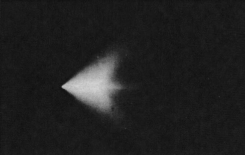
- Carefully scanning the entire celestial sphere takes 4 hours or less.
- Thruster burns of any drive with reasonable power can be detected all the way across the solar system (billions of km away).
- Even with engines cold, the heat from radiators attached to life support will be detectable at tens of millions of km away, which is still far too large to get any sort of surprise.
- Radiating heat in a single direction (away from the enemy) is easily defeated by fielding a number of tiny detector probes which idly coast about the system. Additionally, the narrower of a cone in which you radiate heat, the larger and larger of radiators you need to field. A 60 degree cone of radiation is roughly 10% as efficient, and it only gets worse the tighter of a cone you have.
- Making a huge burn and then trying to stealthily coast for months to the target is do-able, but as long as your enemy can track your first burn, they can very accurately predict where you’ll be as you coast across the solar system. And you still have to worry about radiating your heat for months.
- Decoys are only really viable on really short time scales, such as in combat. Over the long term, study of a decoy’s signature over time will reveal it’s true nature. It would need a power source and engine identical to the ship it’s trying to conceal, as well identical mass, otherwise the exhaust plume will behave differently. This means your decoy needs to be the same mass, same power, same engine as your real ship, so at that point, why not just build a real ship instead?
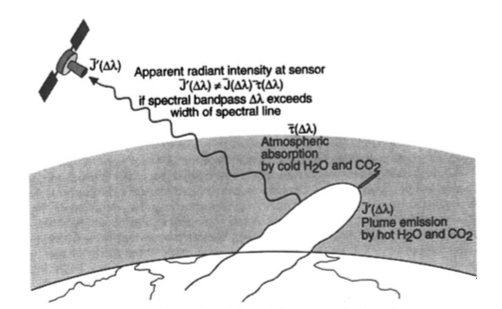
- Hiding behind a planet to make a burn is not really feasible. All it takes is two detectors at opposite sides of this planet to catch this. In reality, a web of tiny, cheap detectors spread across the solar system will catch almost all such cases.
- A combat-ready ship will require very hot radiators for its nuclear powerplant for use in combat. If these radiators are going to be completely cold for the journey, they will suffer enormous thermal expansion stress when activated. In order to avoid this, very exotic and expensive materials for your radiators will be needed to get from 10 K to 1000 K without shattering. Not only that, your radiator armor will need to be similarly exotic, which means it will likely not be very good at armoring your radiators anyways.
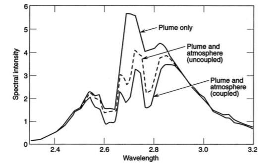
Ultimately, stealth in space is somewhat possible, but current proposed solutions are either ridiculously expensive, impractical, or require you to accept limitations that defeat the purpose of stealth in the first place. Indeed, rather than consider it a ‘yes-or-no’ question, it’s simply a matter of how close you can get to the enemy before they detect you.
In practice, ‘how close’ generally means halfway across the solar system, with expensive stealth solutions reducing that distance only partially. Given this, Children of a Dead Earth runs with the assumption that stealth is not a reasonable military tactic for near future space warfare.
But let’s look at an example of possible stealth: replacing your main engine (nuclear rocket or combustion rocket) with a solar sail. Your exhaust plume is now nonexistent, but now you have to take decades to centuries deliver a military payload anywhere (troops or weaponry). Your best bet is to keep your payload very small if you want to get anywhere in reasonable time. And you still have to worry about your radiators.
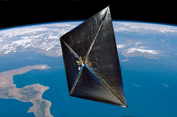
Ironically, this specification of tiny, ‘dumb’ stealth crafts is exactly what you need to build a web of detectors scattered about the solar system. This means the field of cheap detectors you want spanning the solar system can be created stealthily.
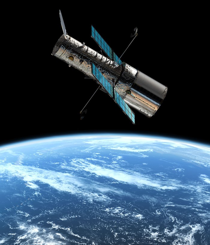
This idea plays a major role in Children of a Dead Earth, as when the enemy drops into orbit around your planet, one must always be wary that the enemy fleet is simply trying to draw out your forces to get a tally on what you actually have. This constantly requires balancing of launching just enough firepower to deal with the enemy without revealing too much about one’s own reserves.
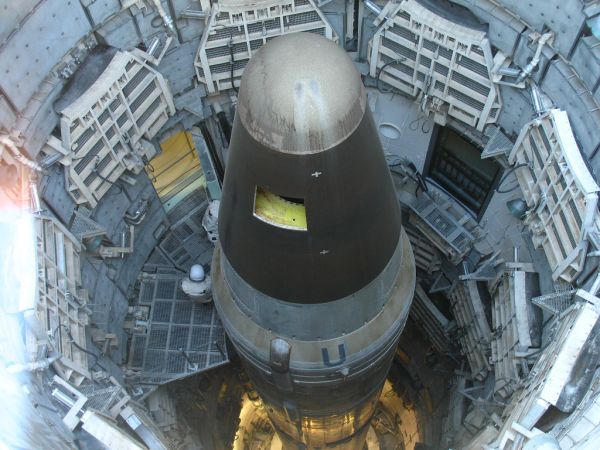
With that all in mind, I will admit that at the beginning of my project, I was dead set on getting stealth to work in space warfare. Ultimately, I came to the conclusion that while stealth in space is certainly possible, it is not feasible given mass, cost, and time constraints. If you want stealth, you need to pay the price of decades-long travel times, enormously massive ships, vastly reduced military effectiveness, or all of the above all at once.
At the beginning of the project, I did explore some more exotic solutions to stealth, but I ultimately wasn’t keen on implementing technologies that were not heavily reviewed and published in scientific articles. At some point though in future posts, I will go over all of the more ‘out there’ technologies I considered for all aspects of space warfare (like a hypothetical nuclear rocket which generates an exhaust plume at 30 K, for instance).
XXX . V000000000 Polymorphism and electronic structure of polyimine and its potential significance for prebiotic chemistry on Titan
Titan is the only place in the solar system, except Earth, where rainfall and seasonally flowing liquids erode the landscape. Whereas the surface pressure is similar to that of Earth, the temperature is extremely low and the dominant liquids are methane and ethane. This makes Titan a test case for exploring the environmental limits of prebiotic chemistry and addressing the question of whether life can develop without water. Experimental and observational data suggest that hydrogen cyanide, the most abundant hydrogen-bonding molecule in Titan’s atmosphere, may polymerize on the surface to polyimine. Using quantum mechanical calculations, we show that polyimine has interesting electronic and structural properties that could potentially facilitate prebiotic chemistry under cryogenic conditions akin to those on Titan.
The chemistry of hydrogen cyanide (HCN) is believed to be central to the origin of life question. Contradictions between Cassini–Huygens mission measurements of the atmosphere and the surface of Saturn’s moon Titan suggest that HCN-based polymers may have formed on the surface from products of atmospheric chemistry. This makes Titan a valuable “natural laboratory” for exploring potential nonterrestrial forms of prebiotic chemistry. We have used theoretical calculations to investigate the chain conformations of polyimine (pI), a polymer identified as one major component of polymerized HCN in laboratory experiments. Thanks to its flexible backbone, the polymer can exist in several different polymorphs, which are relatively close in energy. The electronic and structural variability among them is extraordinary. The band gap changes over a 3-eV range when moving from a planar sheet-like structure to increasingly coiled conformations. The primary photon absorption is predicted to occur in a window of relative transparency in Titan’s atmosphere, indicating that pI could be photochemically active and drive chemistry on the surface. The thermodynamics for adding and removing HCN from pI under Titan conditions suggests that such dynamics is plausible, provided that catalysis or photochemistry is available to sufficiently lower reaction barriers. We speculate that the directionality of pI’s intermolecular and intramolecular =N–H…N hydrogen bonds may drive the formation of partially ordered structures, some of which may synergize with photon absorption and act catalytically. Future detailed studies on proposed mechanisms and the solubility and density of the polymers will aid in the design of future missions to Titan.
Saturn’s moon Titan is a carbon-rich, oxygen-poor world with a wide range of organic compounds, atmospheric energy sources, and alkane liquid seas—all measured by the remarkably successful Cassini–Huygens mission (1). The extreme cold puts liquid water out of reach—buried 50–100 km below a frigid ice crust (2). The lack of liquid water and presence of liquid hydrocarbons makes Titan a unique “natural laboratory” for exploring potential nonterrestrial forms of prebiotic chemistry or, more speculatively, biochemistry, whose essential biopolymers would differ profoundly from terrestrial ones (3). Regardless of the specific chemistry involved, life requires polymorphic molecules that combine flexibility with the ability to form the organized metastable structures needed for function, adaptation, and evolution. This, almost certainly, requires extended molecules capable of intermolecular and intramolecular hydrogen bonding, but such bonds need not involve oxygen; nitrogen is a potential surrogate. Although =N–H…N bonds are weaker than those involving oxygen, their energies are large compared with thermal energy (kT ∼ 0.18 kcal/mol at Titan’s low temperature, 90–94 K) and intermolecular and intramolecular bonds need not compete with the strong –O–H…O hydrogen bonds in water, as on Earth. Thus, they might provide the needed balance between rigidity and polymorphism.
Chemistry in Titan’s atmosphere, which is primarily nitrogen with an admixture of methane, is driven by solar-UV photons and energetic particle radiation to produce hydrocarbons and nitrogen-bearing organics. Cassini–Huygens mission data show that the most abundant nitrogen-bearing product of the atmospheric chemistry is hydrogen cyanide (HCN) (4), which is expected to condense into aerosols that drift down to land and sea. However, HCN has not been observed to be present on Titan’s surface (5); instead, features tentatively identified as consistent with acetonitrile (CH3CN) and cyanoacetylene (HC3N) are observed with the Cassini visible and infrared mapping spectrometer (VIMS). The interpretations of the VIMS spectra in terms of specific non-HCN molecules are reported by Clark et al. (5) as “possible but not definitive,” because of the challenge of observing Titan’s surface through the dense atmosphere and the limited resolution of the instrument. The data do not contradict the view that some or all of the signature is coming from polymers formed from HCN and, more generally, that chemistry on the surface is transforming HCN into other molecules and polymers.
HCN is present in comets (6) and is believed to be a key precursor to the origin of life (7–11). Previous studies have focused on its capability for abiotic synthesis of oxygen-containing molecules (e.g., amino acids and polypeptides), but not on the types of prebiotic chemistry that might occur in oxygen-poor environments. This, combined with the possibility of experimental tests in future exploratory missions to Titan, motivates a deeper understanding of the structure and behavior of HCN polymers and their potential chemistry on Titan.
Using solution-state multidimensional NMR, He et al. (12) found that 75% of the HCN-based polymers formed in laboratory experiments were polyimine (pI) (Fig. 1). These have a flexible C–C bonded backbone and =NH groups that provide for interchain and intrachain hydrogen bonding. These polymers may be present on Titan and escaped detection thanks to observational conditions that make it difficult to identify them spectroscopically (5). Not much is known about them; the only theoretical studies, conducted decades ago, were of isolated polymers and dimers, and used methodologies whose accuracy is now greatly surpassed (13, 14). This contrasts with substituted polyimines/poly-isocyanides, whose synthesis and conformation have been extensively studied experimentally, in part because their helical structures gives them practical and potential importance in electronics, biosensing, and tailored catalysis (14–16).

Lewis structure representation of pI. A flexible single-bonded carbon backbone and complementary intrachain and interchain hydrogen bonding allow for multiple competing 1D conformations and 3D polymorphs.
Here, we use density functional theory (DFT) to computationally explore potential polymorphs (conformations) and the electronic structure of pI. A striking coupling between conformation and electronic band gap is identified, indicating that pI may be able to absorb a wide spectrum of photons, including those available at Titan’s surface. This source of energy could potentially be used to catalyze chemistry relevant to prebiotic evolution, even in the absence of water.
Results
The potential conformational space of pI is large. We have used a combination of plane-wave–based DFT and structure prediction algorithms and molecular calculations of isolated 20-mer models to explore a small but illustrative subset of polymorphs, differentiated primarily by their carbon backbone N=C–C=N dihedral angles. Starting from the extreme of a planar chain, we computationally scanned increasingly coiled conformations, thereby exploring the most important degree of freedom governing pI’s structural and electronic properties (Fig. 2). Infinite chains were studied, and energies per unit HCN were computed and found to be close in energy for all of the polymorphs (∼1–2 kcal/mol HCN; Table 1). We also calculated the packing of each chain in representative 3D lattices. The packed chains had lower energies due to the additional intermolecular =NH…N interactions, but the relative energies were still close. Moreover, the electronic structure was only marginally affected. Therefore, for clarity, we focus on the isolated chains.

Investigated polyimine single chains 3–8. Unit cell width and nearest N–N distances are shown in angstoms.
Calculated properties of HCN (1, 2) and 1D pI chains 3–8
Although the differences between the energies of the different polymorphs reach below the accuracy of the used DFT methodology, the results show that the thermodynamic and kinetic conformational flexibility allowed by the carbon–carbon single-bonded backbone (Fig. 1) ensures that only disordered amorphous materials will be observed at Earth-ambient temperatures (even if, hypothetically, the polymers were completely monodisperse). At Titan’s much lower surface temperature, however, specific polymorphs of the polymer might dominate and even crystallize. As we show below, the span of properties exhibited by these individual polymorphs are nothing short of remarkable—each having its own electronic, optical, and mechanical properties.
We can speculate that, in addition to relying on =N–H…N hydrogen bonding, any prebiotic processes on Titan might benefit, to some degree, from the dynamic making and breaking of covalent bonds. This would be advantageous for the assembly of primary structures (polymers) of reasonably low dispersity. Because of the low temperature, the first step in gauging the plausible existence of any such processes on Titan is finding a system with near-equilibrium thermodynamics for polymerization and depolymerization.
We have estimated the heat of reaction for pI polymerization, pI(∞) + 1 HCN → pI(∞), in the condensed phase, ΔHr,90K = −5.6 kcal/mol HCN, using a thermodynamic cycle detailed in SI Appendix. The cycle corrects accurate gas phase calculations with experimentally known heats of sublimation of HCN (ΔHsub0 = 9.0 kcal/mol) and calculated energies of sublimation/interaction of the infinite chains [ΔEpI(s)→pI(g) ∼ 1 kcal/mol HCN]. ΔHr,90K = −5.6 is not exact, but we believe it offers a reasonable approximation to pI chain propagation in the solid state, or on surfaces where HCN monomers are hydrogen bonded before reaction. The Gibbs energy, ΔGr,90K, will be closer to zero still, due to the negative entropy associated with polymerization. The relevant activation barrier is unknown; however, it may be significantly reduced by tunneling, catalysis, photoexcitation (Fig. 3), or a combination of all three. If the thermodynamics of polymerization, <5 kcal/mol, were to represent the kinetic barrier to depolymerization of pI, reactions that shuffled polymer connectivity could proceed within seconds on Titan, thereby allowing for a dynamic chemical environment. HCN is from this aspect markedly different from the formally isoelectronic, and thermodynamically irreversible [ΔHr = −40 kcal/mol (17)] polymerization of acetylene to polyacetylene, which might also occur on Titan.

Calculated band gaps of different polymer conformations provide a first approximation to their light absorption maximum (Right). The band gaps of pI polymorphs span a range of 3 eV and absorb across the entire visible spectrum and into the UV. The lowest ...
It is beyond the scope of the present work to undertake studies of explicit reaction mechanisms or processes that may allow for such dynamics. We would, however, like to point to a few possibilities. What is most striking about pI is the multitude of different hydrogen-bonded networks possible both within and in-between polymer chains. Fig. 4A highlights a triad of =NH groups capable of both donating and accepting hydrogen bonds, a structural unit not markedly different from an “oxyanion hole” situated in the active site of many enzymes (18). In enzymes, closely spaced oxyanion holes are known to work in tandem to stabilize transition states of different steps in a chemical transformation (19). Similar structural motifs are common in various man-made bioinspired catalysts (20, 21). The different polymorphs we have considered demonstrate that the alignment of =NH groups can generate large dielectric moments. This is intriguing for many reasons: electrostatic preorganization is known to occur in many enzymes and believed to be key to their catalytic function (22). Structures such as that shown in Fig. 4A might thus be catalytically active, and facilitate prebiotic reaction chemistry on Titan.

(A) Chain 6 illustrates that “oxyanion hole”-like catalytic centers, a common feature of many enzymes, is a structural feature of pI. The ability of some conformations to generate electric fields by the alignment of =NH groups may give ...
Quantum tunneling is another possibility. It can be important for cryogenic reactivity (23), including astrochemistry (24) and even biochemistry (25), and could play a role in allowing for chemistry on the surface of Titan.
Photon capture may provide activation energy for, and thereby synergize with, such catalytic mechanisms. A key question is whether pI can absorb photons at the wavelengths available on Titan, and analyzing the electronic structure of pI (Fig. 4 C–E) permits consideration of possible photon-induced low-temperature reactivity of the different polymorphs.
The electronic structure of polymorph 8 predicts it to have a band gap of 1.5 eV, which corresponds to a maximum light absorption in the 830 nm (infrared) range. From this minimum, increasing of the N=C–C=N dihedral angle widens the band gap, causing higher energy photons of visible and later UV wavelengths to be absorbed instead. The lowest energy structure, 7, is predicted to absorb yellow light in the 560 nm (2.2 eV) region. It is easy to realize how numerous other chain configurations may enable pI to access wavelengths across the entire 3-eV range laid out between the extremes 3 and 8. Fig. 3 compares the calculated range of possible pI photon absorption with wavelengths corresponding to regions of relative transparency in Titan’s atmosphere where more photons reach the surface.
How can we understand the remarkable structure–function relationship of pI? Fig. 4C displays how the lowest conduction band runs up (from Γ → X), not down as expected from a nitrogen-π* band at the zone center Γ. This is due to concurrent C–C π-bonding at Γ, which weakens as we move Γ → X. The density of states of chain 8 in Fig. 4D have been projected onto individual orbital contributions, namely the out-of-plane and along-chain directional 2p orbitals on nitrogen. The nitrogen 2p levels dominate the top of the valence band and most of the bottom of the conduction band, where carbon 2p also contributes slightly. This explains why changes in the N=C–C=N dihedral angle affect the overlap of adjacent p orbitals, which in turn modulate the band gap of pI (Fig. 3). Together with the projected crystal orbital Hamilton population (pCOHP) bonding analysis shown in Fig. 4E, it tells us two things: first, partial occupation of the lowest conduction band weakens C–N bonds and strengthens the C–C backbone. Occupation of the conduction band may occur both via chemical reduction or via photochemical excitation. Second, a small in-plane repulsion between adjacent nitrogen atoms does exists [in agreement with early predictions by Kollmar and Hoffmann (13)]; it is one reason for distortion from the planar geometry (e.g., 8 → 7).
Speculations on the Implications of These Results for Life Without Water.
A sine qua non of life is the formation of compartments allowing local entropy reduction. Although terrestrial biological compartmentalization is typically achieved using highly evolved protein shells (viruses) or bilamellar membranes (cells) that surround 3D volumes, localization of interacting molecules to (effectively) 2D compartments by polymer monolayers is a simpler possibility and could be important during the early stages of molecular evolution. The polarity and ability of pI polymers to form intermolecular hydrogen bonds suggests the possibility that they might form alkaphobic monolayers in Titan’s alkane-rich environment—mirroring the hydrophobic Langmuir films formed by hydrocarbon polymers on Earth. The interaction strength of ∼1 kcal/mol HCN between chains would be adequate to maintain such secondary structures once formed. At Titan’s low temperatures, these would be solid; however, because of comparable energies of different chains conformations (Table 1), they could contain a mixture of ordered and disordered regions with enough defects to permit lateral migration and interactions between inserted smaller molecules. Stacked lamellae, like those formed in crystal melts, is another possibility (Fig. 4B). Small pI crystals or chain-folded lamellae formed during the sedimentation of atmospheric polymers (i.e., in processes analogous to melt cooling) might nucleate and template lamellar extension on Titan’s surface. Possibilities like this, although consistent with the energetic and electronic calculations presented above, are very speculative and intended as a suggestion of the kinds of structures that might occur, rather than a specific prediction. Because they are impossible to form naturally in a warmer world containing water and oxygen, only future exploratory missions to Titan can test the hypothesis that natural chemical systems evolve chemical complexity in almost any circumstance .
The larger seas of Titan have been determined by radar sounding to be mostly methane with significant admixtures (∼10%) of ethane and nitrogen . Because HCN is mostly insoluble in such mixtures (29), it is unlikely that polymers will form there. Rather, it is more likely that the materials investigated herein may undergo reactions in tidal pools near the shores of seas and lakes, where geological activity, tidal effects associated with Titan’s noncircular orbit, and changes in the hemispherical distribution of sunlight caused by ∼105-y variations in Saturn’s orbit could provide a more dynamic environment . Seasonal emptying and refilling of the smaller liquid “lakes,” such as Ontario Lacus in the Southern Hemisphere, and longer-timescale variations in sea levels associated with Saturn’s orbital variations, may allow cycling of these materials between liquid and dry (shoreline) environments, where they would be well positioned to undergo further chemistry. Although the densities of the investigated crystals in our work are in the range of 1.2–1.4 g/cm3 (SI Appendix, Table S1), well above the expected density of Titan’s seas (0.4–0.7 g/cm3) , defects and lacunae might reduce the density enough to permit individual or stacked lamellae to float. Copolymerization with acetylene, or heterodispersion of polyacetylene, a somewhat related polymer [density of ∼0.4 g/cm3 ] in pI could further reduce the density.
Detection of the solid polymers on Titan will be difficult from remote sensing. Direct chemical analyses on the surface either in lakes and seas or on the adjacent shorelines by in situ techniques seems more promising, but will require sending an instrumented lander to Titan’s surface . Laboratory studies of the solubility and density of pI and other related polymers will aid in the decision of whether to send such a probe to the seas—where targeting and sampling is easier—or to the technically more challenging shoreline/dry environments.
Implications for Chemistry, Functional Materials, and Catalysis.
Whereas we have framed this study from a planetary chemist’s point of view, it is important to realize that different kinds of polyisocyanides (poly-RNC, substituents R different from H) are of interest also in a more general sense. It has been established that the most common conformation of these polymers are fourfold sized helices . This contrasts with our results, which suggests that a wave conformation and the possibility of sheet structures become competitive when R=H. The sixfold conformation is also predicted to be of lower energy than the fourfold conformation that has been experimentally inferred with larger R groups. Structural properties such as helical pitch and handedness are of obvious importance in biology where α-helices and β-sheets have profound influence on biological activity. Different main-chain conformations can display different optical properties, and non–HCN-based chiral polyisocyanides, with either right-handedness or left-handedness, have been synthesized . The conformation–band gap connection shown in Fig. 4 is an extreme example of a structure–function relationship, and our results carry with them a suggestion of utility: The conformations of pI, consisting formally of hydrogen isocyanide units, may be valuable models for functional materials design. The purposeful design of ferroelectric materials that respond to external electric fields is one example. Consider, for instance, the alignments of local dipoles arising from =NH groups and how polarization is generated along the chain axis in 6 (Fig. 2), whereas this is not possible in 7 or 8. Other examples include the design of nanowires for devices and, as we have speculated, chiral catalysts. This could be undertaken by chemically modifying (and rigidifying) a pI scaffold. Therefore, in addition to being of interest for prebiotic chemistry in the outer solar system, the pI polymer holds promise as an instructive model material for the study of emergent properties, including semiconduction, ferroelectricity, and catalysis.
Materials and Methods
Extended Calculations.
Extended DFT calculations were performed using the Vienna ab initio simulation package (VASP), version 5.3.5 . Geometries were optimized using the Predew–Burke–Ernzerhof (PBE) generalized gradient approximation functional. Standard projected augmented wave potentials , were used together with a plane-wave kinetic energy cutoff of 600 eV. Brillouin zone sampling was performed on Γ-centered k meshes with a reciprocal space resolution of at least 2π × 0.03 Å−1. Energies and forces were converged to <1 meV per atom. For 1D chains, each chain was separated by >10 Å in the periodic calculation, and the k-mesh density refers to the length dimension along the chain. We used the Heyd–Scuseria–Ernzerhof (HSE06) screened-hybrid functional for final estimates to relative energies and band gaps. HSE06 has a reported mean absolute error of 0.2 eV for band gaps .
Structure Searching.
Chain conformations and 3D lattices were surmised by a hybrid approach: chain conformations corresponding to structures 5 and 7 were identified by geometric optimization of manually constructed molecular 20-mer structures in vacuum. Molecular calculations were performed using the hybrid ωB97X-D density functional in conjunction with a 6-31+G(d,p) basis set, as implemented in Gaussian 09 revision D01 . ωB97X-D is a general-purpose DFT functional with demonstrated high accuracy for thermochemistry for main group elements. Optimized molecular structures were subsequently used to create input for periodic DFT calculations. Other chain conformations (3, 4, and 6) were identified by particle-swarm optimization (PSO) structure searches. The PSO searches were performed by coupling VASP with the CALYPSO code . Identification of representative 3D lattices of pI was possible following repeated PSO searches over the H1C1N1 stoichiometry, while allowing for 1–6 units of HCN per unit cell. The final structures [1D chains 3–8 (Fig. 2) and select 3D lattices thereof (SI Appendix)] span a wide and representative range of N=C–C=N dihedral angles. A very large number of other conformations are, of course, also possible. The exact 3D structures are unlikely to represent the thermodynamic global minimum of the corresponding 1D chains in the condensed phase, but they do represent reasonable approximations to the influence of a chemical environment (∼1 kcal/mol, HCN).
Thermal Corrections.
The combined HSE06/PBE approach reasonably reproduces the National Institute of Standards and Technology experimental heat of sublimation of crystalline HCN (ΔHsub,calc, 7.4 kcal/mol, and ΔHsub,exp, 9.0 kcal/mol, determined between 202 and 254 °C), when corrections for thermal motion and consideration of rotational and translational degrees of freedom are included (the thermally noncorrected ΔEsub,calc is 8.2 kcal/mol). Thermal corrections were obtained by phonon calculations, which proceeded following the calculation of tightly converged (1 × 10⁻⁸ eV/HCN) PBE geometries. Force constants were obtained through the direct method , i.e., from Hellmann–Feynman forces induced by small displacements introduced to a [5 × 5 × 5]-supercell of the HCN crystal unit cell, using the PHONOPY 1.9.7 code . Phonon calculations could not be performed on pI. Near free rotation around carbon–carbon bonds is implied by similar energies of many different conformers. This, in combination with the possibility of irrational helical pitches requires the use of large unit cells, which make such calculations prohibitively expensive. Analytical vibrational analyses on the molecular 20-mer models of 6, 5, and 7 did, however, identify those as true minima on the potential energy surface, which allowed for calculation of thermal and entropic (1 atm, 90 K) correction for the gas phase polymerization reaction.
Electronic Structure Analysis.
pCOHP bonding analyses and orbital projections of pI’s density of state were done using the LOBSTER program
on the electronic structure of pI, including frontier orbitals of select 20-mer models and band-decomposed charge densities of extended systems; summation of relative energies, structures and band gaps of 1D chains and corresponding 3D lattices, and xyz coordinates and unit cells of all structures considered; and description of the thermodynamic cycle used to approximate condensed-phase polymerization.
============ MA THE SPACE ELECTRONIC GOOD MATIC ============
Tidak ada komentar:
Posting Komentar