

LED display
An LED display is a flat panel display, which uses an array of light-emitting diodes as pixels for a video display. Their brightness allows them to be used outdoors where they are visible in the sun for store signs and billboards, and in recent years they have also become commonly used in destination signs on public transport vehicles, as well as variable-message signs on highways. LED displays are capable of providing general illumination in addition to visual display, as when used for stage lighting or other decorative (as opposed to informational) purposes.
The first true all-LED flat panel television screen was possibly developed, demonstrated and documented by James P. Mitchell in 1977. Initial public recognition came from the Westinghouse Educational Foundation Science Talent Search group, a Science Service organization.[1] The paper entry was named in the "Honors Group" publicized to universities on January 25, 1978.[2] The paper was subsequently invited and presented at the Iowa Academy of Science at the University of Northern Iowa.[3][4] The operational prototype was displayed at the Eastern Iowa SEF[5] on March 18 and obtained a top "Physical Sciences" award and IEEE recognition. The project was again displayed at the 29th International SEF at the Anaheim Ca. Convention Center on May 8–10.[6] The ¼-inch thin miniature flat panel modular prototype, scientific paper, and full screen (tiled LED matrix) schematic with video interface were displayed at this event.[7][8] It received awards by NASA[9] and General Motors Corporation.[10][11][12] This project marked some of the earliest progress towards the replacement of the 70+ year old high-voltage analog CRT system (cathode-ray tube technology) with a digital x-y scanned LED matrix driven with a NTSC television RF video format. Mitchell's paper projected the future replacement of CRTs and included foreseen application to battery operated devices due the advantages of low-power. Displacement of the electromagnetic scan systems included the removal of inductive deflection, electron beam and color convergence circuits and has been a significant achievement. The unique properties of the light emitting diode as an emissive device simplifies matrix scanning complexity and has helped the modern television adapt to digital communications and shrink into its current thin form factor.
The 1977 model was monochromatic by design. The efficient Blue LED completing the color triad, did not arrive for another decade. Large displays now use high-brightness diodes to generate a wide spectrum of colors. It took three decades and organic light-emitting diodes for Sony to introduce an OLED TV, the Sony XEL-1 OLED screen which was marketed in 2009. Later, at CES 2012, Sony presented Crystal LED, a TV with a true LED-display (in which LEDs are used to produce actual images rather than acting as backlighting for other types of display, as in LED-backlit LCDs which are commonly marketed as LED TVs).
The 2011 UEFA Champions League Final match between Manchester United and Barcelona was broadcast live in 3D format in Gothenburg (Sweden), on an EKTA screen. It had a refresh rate of 100 Hz, a diagonal of 7.11 m (23 ft 3.92 in) and a display area of 6.192×3.483 m, and was listed in the Guinness Book of Records as the largest LED 3D TV.

XO___XO TEXT ELECTRONIC LED PANELS
(Electronic information panels just for text)
Text LED panels are targeted for displaying text only. It can display letters, number and other characters, but no graphics which does not fit into one line. We offer several sizes of the panels.
Panels with small number of lines are suitable for departure time showing on the platform, from which the vehicle should leave, i. e. each platform can be equipped by one display, which shows departures from that platform. This concept simplifies passenger’s orientation on the station or whole terminal.
Panels with higher number of lines and high number of characters on a line should be located at the entrance of the terminal or the station. Can help people find the right platform for their connection. It also shows time of departure or delay.
Communication and control unit provides:
- Ethernet connection over optical fibres to dispatching office. Communication interface can be adjusted to local situation. (RS485).
- Interface for the receiver for the sightless people
- Cooling fan control for extended lifetime
- LED voltage control ability for low power consumption and independent illumination control on both sides of the panel.
The panel is commanded by SW based on requests from the central server.
The panels comply to the norm EN 60721 – 3 – 5 for rain resistance (6 mm/min) and sunshine intensity (1200 W/m2 for 8 hours).
There are textual signs to give meaning to displayed information on the border of the panel.
Electronic panels for platforms
Are intended to be placed on a platform, therefore it does not have to show the platform number. Their color is based on the customer’s wish (both case and LED color)
Basic parameters of panels ELP 401:
- Dimensions of 2 line panel: 130 x 33 x 23 (l x h x d) [cm].
- Double-sided display area with 20×120 point of high illumination LED diodes (spacing 8 mm).
- Front side including LEDs can be fold up. It is holded on pistons.
- Each side has independent brightness control by its own light sensor.
- Maximal power consumption 220VA.
- Actual power consumption when full sunshine is about 40W.
- Night power consumption – less than 12W (without LED light less than 8W).
- White LED panel 20 x 120 – type ELP 401WE.

- Red LED panel 20 x 120 – type ELP 401RE.

Overview text information panels
Unlike small platform displays these bigger alternatives can display supplementary information as platform number, departure time, current time. Digital announcer, amplifier 15W/4Ohm and receiver for sightless people is integrated as well. Everything is moisture resistant.
Basic parameters of big panels ELP 411 (single-sided) a ELP 421 (dual-sided):
- Dimensions of single-sided LED panel – 8 lines: 230 x 130 x 16 (l x h x d) [cm].
- Dimensions of double-sided LED panel – 8 lines: 230 x 130 x 23 (l x h x d) [cm].
- Active area 80×280 points with high brightness LED diodes (spacing 8 mm).
- The front panel can be fold up and holds on pistons.
- Each side illumination is independently controlled by a sensor.
- Maximal single-sided LED panel power consumption: 850VA – red, yellow; 1060VA – white.
- Maximal double-sided LED panel power consumption 1700VA – red, yellow, 2100VA – white
- Actual power consumption in direct sun – single-sided 250W; double-sided 500W.
- Night power consumption – less than 50W
Big text panel contains 23 200 LED on one side. Double sided thus contains 46 400 LED.

Big textual LED panel 80 x 280 - type ELP 411RE.
XO__XO XXX PRACTICAL LED INDICATOR AND FLASHER CIRCUITS
The most widely used of all optoelectronic devices is the simple LED (light emitting diode), which emits a fairly narrow bandwidth of visible (usually red, orange, yellow, or green) or invisible (infrared) light when its internal diode junction is stimulated by a forward electric current.
LEDs have typical power-to-light energy conversion efficiencies some 10 to 100 times greater than a simple tungsten filament lamp and have very fast response times (less than 0.1µS, compared to 10s or 100s of milliseconds for a tungsten lamp), and are thus widely used as visual indicators and as simple ‘flashing light’ units. A variety of such circuits are shown in this article.
LED BASICS
INTRODUCTION
Figure 1 shows the standard symbol that is used to represent an LED in this article, together with its basic anode (a) and cathode (k) terminal notations.
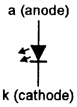
FIGURE 1. Standard LED symbol, together with its terminal notations.
LEDs are pn junction diodes, usually made from gallium arsenide (GaAs) or aluminum-gallium arsenide (AlGaAs) types of semiconductor materials, and emit light when stimulated by a forward current.
Roughly 2V are developed across them when passing a useful forward current; Figure 2 lists the typical forward volt drops (Vf) of different colored standard 5mm diameter LEDs at forward currents of 20mA.
| COLOR | Red | Orange | Yellow | Green | Blue |
|---|---|---|---|---|---|
| Vf (typical) | 2V | 2V | 2.1V | 2.2V | 3.3V |
FIGURE 2. Typical forward voltage values of standard LEDs at a current-limited value of 20mA.
If an LED is reverse-biased, it starts to pass significant current at a fairly low voltage value (typically 3V to 5V) and eventually avalanches (zeners) at higher voltages.
LEDs are available in a variety of styles, the most popular being the ‘round’ type that has the basic shape shown in Figure 3 and which is readily available in standard diameter sizes of 3mm, 5mm, 8mm, or 10mm. Round LEDs use a clear or colored plastic case with a lens molded into its dome, and are designed to be viewed end-on, looking towards the dome, as indicated in the diagram.
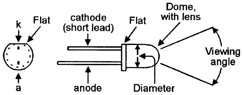
FIGURE 3. Typical physical details of ‘round’ LEDs and methods of recognizing their polarity.
The LED case has a polarity-identifying ‘flat’ molded into the side of its base adjacent to the cathode lead, which is usually shorter than the anode lead when untrimmed. Special fittings are readily available for fixing most sizes of LED to front panels, etc.
One important but confusingly-named LED parameter is its ‘viewing angle,’ at the extremes of which the LED’s optical output intensity falls to half of its maximum axial value. Some LEDs give a diffused output in which the light intensity falls off gradually beyond the viewing angle and is thus clearly discernable over a wide angular range; others (particularly ‘Hyperbright’ types) have a sharply focused output in which the light intensity falls off very sharply beyond the specified viewing angle.
LEDs are available in five different ‘brightness’ categories, which are usually known as Standard, High Brightness, Super Bright, Ultrabright, and Hyperbright. The brightness level is usually specified in milli-candelas (mcd), with the LED passing an operating current of 20mA. The table in Figure 4 presents typical optical output-power and viewing-angle figures for the five types of 5mm round LED. Note in the ‘red’ LED column that the Ultrabright and Hyperbright devices (which use water-clear lenses) are 143 and 500 times brighter, respectively, than a standard red LED.
| LED Type | Viewing Angle | Red | Green | Orange |
|---|---|---|---|---|
| Standard | 60° | 7mcd | 5.2mcd | 8mcd |
| High Brightness | 40° | 30mcd | 25mcd | 50mcd |
| Super Bright | 30° | 125mcd | 120mcd | 140mcd |
| Ultrabright | 25° | 1000mcd | — | — |
| Hyperbright | 25° | 3500mcd | — | — |
FIGURE 4. Typical optical output power figures — in millicandelas — of five basic types of 5mm round red, yellow, and green LEDs.
In use, an LED must be wired in series with a current-limiting device such as a resistor. Figure 5 shows how to work out the resistance (R) value needed to give a particular current from a particular DC supply voltage. Thus, if a red LED is required to operate at 20mA from a 10V supply, R needs a value of (10V - 2V)/0.02A = 400R. In practice, R can be connected to either the anode or the cathode of the LED.
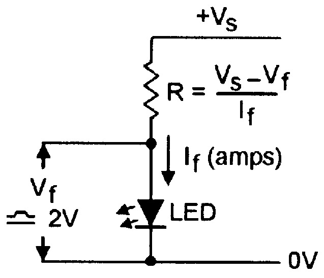
FIGURE 5. Method of finding the R value for a given VS and If.
A LED can be used as an indicator in an AC circuit by wiring it in inverse parallel with a IN4148 (or similar) silicon diode, as shown in Figure 6, to prevent the LED from being reverse-biased; the LED is fed with a half-wave current in this mode, so — for a given brightness — the ‘R’ value must be halved relative to that indicated in the Figure 5 DC circuit.
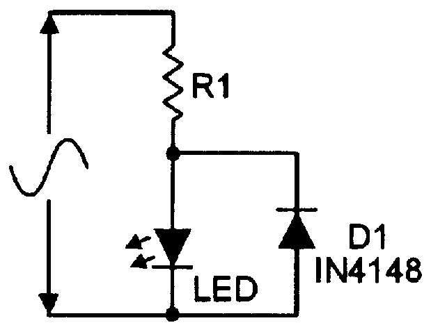
FIGURE 6. Using an LED as an indicator in an AC circuit.
SPECIAL-PURPOSE LEDS
LEDs are readily available in a variety of special-purpose forms, the best known of which are the ‘direct connection’ type, the ‘flasher’ type, and the multicolor types.
Direct connection LEDs are designed to be connected directly across a fixed-value DC or AC voltage source. DC voltage types take the basic form shown in Figure 7(a) and incorporate a current-limiting resistor that is housed in the LED body in 5V and 12V types, or in one of the LED leads in higher voltage types. AC voltage types (usually designed for use with 110V or 240V supplies) take the basic form shown in Figure 6, but are usually housed in an insulated panel-mounting assembly.
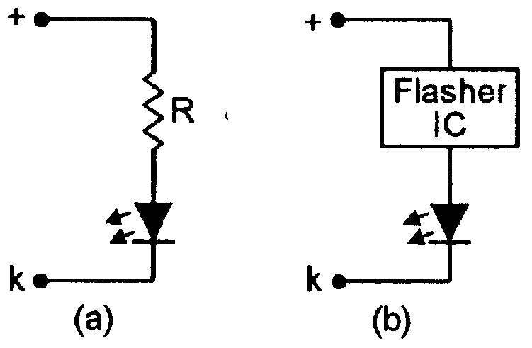
FIGURE 7. Basic form of a direct connection DC LED (a) and a flasher LED (b).
Flashing LEDs take the basic form shown in Figure 7(b) and have a built-in integrated circuit that gives the flashing effect. They are available in red, green, and yellow, have a typical flashing frequency of 2Hz, and can (typically) use 6V to 12V DC supplies.
Multicolor LEDs are actually two-LED devices. Figure 8 shows a ‘bi-color’ device that comprises a red and a green LED connected in inverse parallel, so that the color green is generated when the device is connected in one polarity, and red is generated when it is connected in the reverse polarity. This device is useful as a polarity or null indicator.
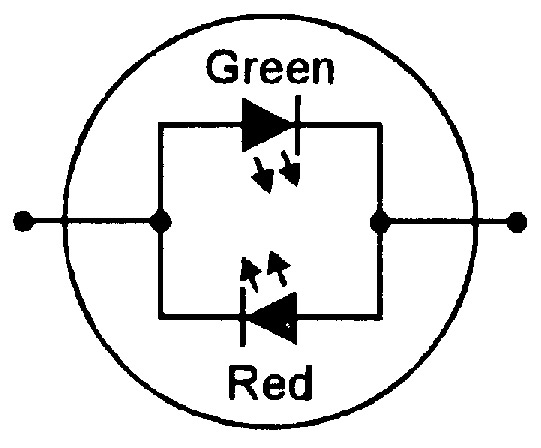
FIGURE 8. Bi-color LED actually houses two LEDs connected in inverse parallel.
Figure 9 shows another type of multicolor LED, which is sometimes known as a ‘tri-color’ type. This comprises a green and red LED mounted in a three-pin common-cathode package. This device can generate green or red colors by turning on only one LED at a time, yellow by turning both LEDs on by equal amounts, or any color between green and red by turning both LEDs on in the appropriate ratios.
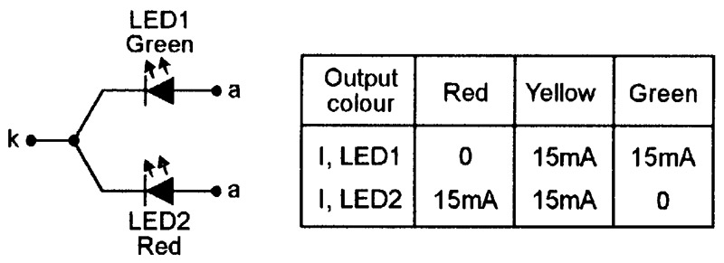
FIGURE 9. Multicolor LED, giving three colors from two junctions.
MULTI-LED CIRCUITS
If several LEDs need to be driven from a single power source, this can be done by wiring all LEDs in series, as shown in Figure 10, provided that the supply voltage is significantly greater than the sum of the individual LED forward voltages.
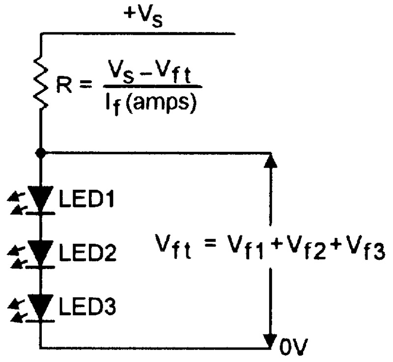
FIGURE 10. LEDs wired in series and driven via a single current-limiting resistor.
This circuit thus consumes a minimum total current, but is limited in the number of LEDs that it can drive. Any number of these basic circuits can, however, be wired in parallel, so that any number of LEDs can be driven from a single source, as shown in the six-LED circuit in Figure 11.
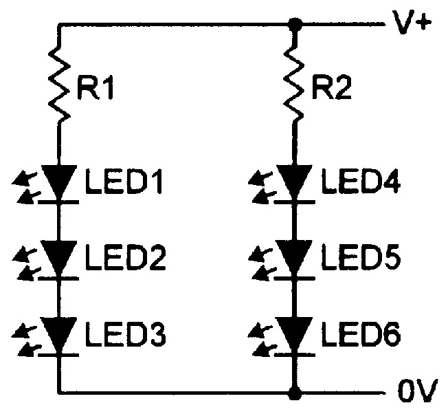
FIGURE 11. Any number of Figure 10 circuits can be wired in parallel, to drive any number of LEDs.
An alternative way of simultaneously powering several LEDs is to simply wire a number of the Figure 5 circuits in parallel, as shown in Figure 12. Note, however, that this circuit is very wasteful of supply current (which equals the sum of the individual LED currents).
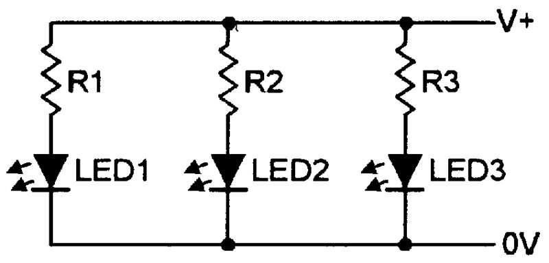
FIGURE 12. This circuit can drive any number of LEDs, but at the expense of high current.
Figure 13 shows a “what not to do” LED-driving circuit, in which all the LEDs are wired directly in parallel. Often, this circuit will not work correctly because inevitable differences in the forward characteristics of the LEDs cause one LED to hog most or all of the available current, leaving little or none for the remaining LEDs.
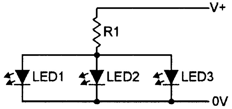
FIGURE 13. This LED-driving circuit may not work; one LED may hog most of the current.
LED FLASHER CIRCUITS
SIMPLE DESIGNS
One of the simplest types of LED display circuit is the LED flasher in which a single LED repeatedly switches on and off, usually at a rate of one or two flashes per second. A two-LED flasher is a simple modification of this circuit, but is arranged so that one LED switches on when the other switches off, or vice versa.
Figure 14 shows the practical circuit of a transistor two-LED flasher, which can be converted to single-LED operation by simply replacing the unwanted LED with a short circuit.
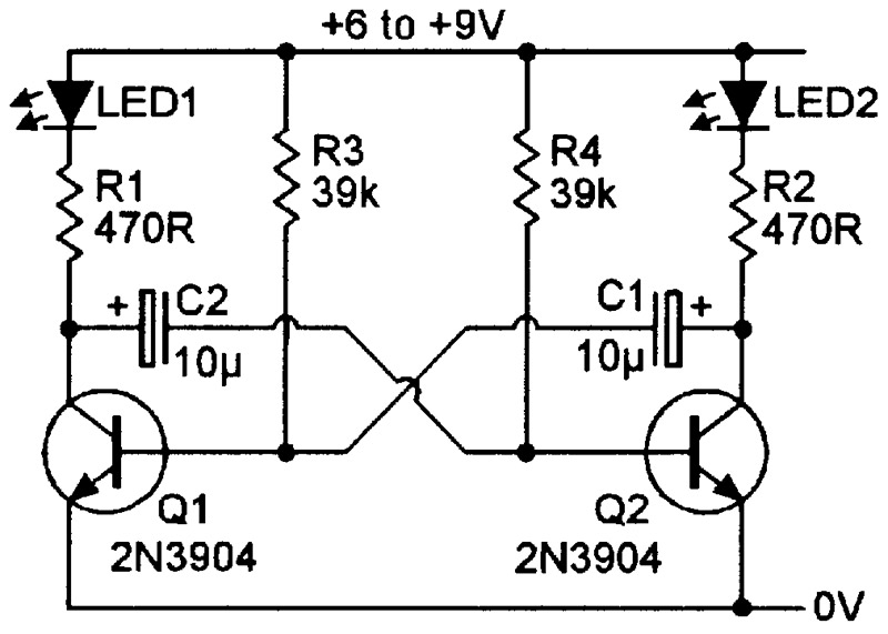
FIGURE 14. Transistor two-LED flasher circuit operates at about 1Hz.
Here, Q1 and Q2 are wired as a simple 1Hz astable multivibrator, in which Q1 and LED1 turn on as Q2 and LED2 turn off, and vice versa, and in which the astable switching rates are controlled by the values of C1-R3 and C2-R4.
Figure 15 shows an IC version of the two-LED flasher, based on a 555 or 7555 timer IC that is wired in the astable mode, with its main time constants determined by the C1 and R4 values and giving a cycling rate of about 1Hz (one flash per second). The circuit action is such that output pin 3 of the IC alternately switches between the ground and the positive supply voltage levels, alternately pulling LED1 on via R1 or driving LED2 on via R2. The circuit can be converted to single-LED operation by omitting LED2 and R2.
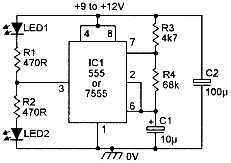
FIGURE 15. IC two-LED flasher circuit operates at about 1Hz.
Figure 16 shows a useful modification of the above circuit, in which the flashing rate is made variable via RV1, and two pairs of series-connected LEDs are connected in the form of a cross so that the visual display alternately switches between a horizontal bar (LED1 and LED2 ON) and a vertical bar (LED3 and LED4 ON), thus forming a visually interesting display. The cycling rate is variable from 0.3 to 3 flashes per second.
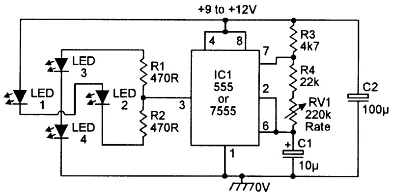
FIGURE 16. The rate of this four-LED double-bar flasher is variable from 3 to 0.3 flashes per second.
MICROPOWER LED FLASHERS
Simple LED flasher circuits of the types shown in Figures 14 to 16 consume mean operating currents of several milliamps. Micropower LED flashers, on the other hand, consume mean operating currents that are measured in microamps (typically ranging from 2µA to 150µA), and are intended mainly for use in battery-powered ‘emergency indicator,’ ‘battery state,’ and ‘burglar deterrent’ applications.
In emergency indicator applications, micropower LED flashers can be used to indicate the positions of emergency exits, lanterns, torches, alarm buttons, or safety equipment, etc., under dark conditions (perhaps caused by a failure of a main lighting system). When used as battery state indicators, they are often fitted in smoke alarms and other low-current long-life units that are powered by 4.5V to 12V batteries. When used as burglar deterrents, they are prominently fitted to real or dummy burglar alarm control or alarm/siren boxes or CCTV cameras, etc.
To understand the basic principles behind micropower LED flashers, you must first learn some basic facts concerning visual perception, as follows.
- The human eye/brain combination is sharply attracted by sudden changes in visual patterns or light levels; it is particularly sensitive to some types of flashing light. Figure 17 shows the typical ‘light flash’ response of the human eye/brain combination when presented with a bright LED-generated pulse of light.
- Note from Figure 17 that the flash must be present for at least 10mS to be seen (perceived) at full brilliance, and that — when the flash terminates — the ‘persistence of vision’ effect causes the perceived brilliance to decay fairly slowly, typically taking 20mS to fall to 50% of its maximum (pre-switch off) value. Consequently, the eye can only see flashing lights as individual flashes if they are separated by a period of at least 20mS; if they are separated by less than 20mS, they are seen (because of the ‘persistence of vision’ effect) as a continuous light.
- Also note from Figure 17 that — if the flashes are separated by at least 20mS — the brain ‘sees’ the individual flashes at full brilliance if they have a duration of 10mS or greater, but sees them at diminishing brilliance at durations below 10mS (a 2mS flash appears at roughly 1/5th of true brilliance; the perceived brilliance falls off rapidly at durations below 1mS). The perceived duration of a 20mS flash (30mS) is only 50% greater than that of a 10mS flash (20mS).
- The human eye/brain combination is very sharply attracted by flashing lights that have repetition periods in the approximate range 0.5 to 5 seconds, but is less attracted by flashing lights that have repetition periods above or below this range.
- Modern low-cost Super Bright LEDs, when generating a 10mS or longer light pulse, produce a brightness level that is adequately eye-catching for most practical purposes when pulsed by a 2mA current.
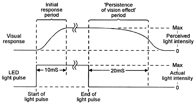
FIGURE 17. Typical ‘light flash’ response of the human eye/brain combination.
When the above sets of facts are put together, it transpires that the ‘ideal’ micropower LED flasher — when using a Super Bright LED — should produce a pulse with a duration (d) of 10mS at a current (I) of 2mA, at a repetition period (p) of 2 seconds (= 2000mS). Note that, under these conditions, the mean current (Imean) of the LED is given by
Imean = I x d/p
and is a mere 10µA in this particular example (at a 30 second repetition period, Imean is a minute 0.67µA).
In practice, the actual mean current consumed by a micropower LED flasher circuit is equal to the sum of the LED and the driver currents, and is inevitably higher than the minimum figure indicated above. Figures 18 and 19, for example, show two alternative micropower LED flasher circuits that — when powered from 6V supplies — consume total currents of 86µA and 12µA, respectively.
The Figure 18 circuit is designed around a CMOS 7555 ‘timer’ IC that is used in the astable mode and typically consumes an unloaded operating current of 75µA at 6V. In this mode, C1 alternately charges up via R1-R2 and discharges via R2 only, thus generating a highly asymmetrical output waveform on pin 3, which pulls the LED on via current-limiting resistor R3 during the brief ‘discharge’ part of each operating cycle.
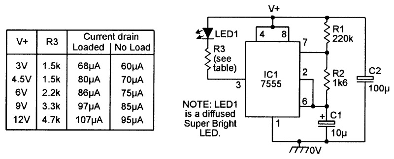
FIGURE 18. Circuit and performance details of a 7555-based micropower LED flasher unit.
The Figure 18 table summarizes the circuit’s performance details when optimized for operation at various spot voltages in the range 3V to 12V.
The Figure 19 circuit is designed around a CMOS 4007UB IC, which contains two complementary MOSFET transistor pairs plus one CMOS inverter, all housed in a 14-pin DIL package.
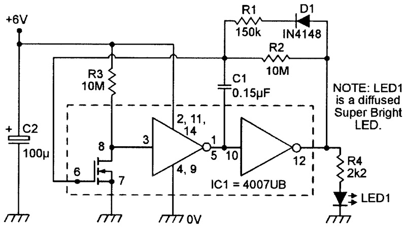
FIGURE 19. This 4007UB-based micropower LED flasher circuit consumes a mean current of 12µA at 6V.
In this application, the IC is wired as a micropower ring-of-three asymmetrical astable multivibrator which — when powered from a 6V supply — drives the LED on for 10mS at two-second repetition intervals; the ON time is controlled by C1-R1, the OFF time by C1-R2, and the LED current (2mA nominal) is controlled by R4. The circuit consumes an unloaded operating current of 2µA, and a loaded current (when driving the LED with 2mA pulses) of 12µA.
Note that the basic circuit of Figure 19 can be used at any supply voltages in the range 4.5V to 12V, but that the actual component values must be selected to suit the specific supply voltage used. Also note that — at supply voltages of 6V or greater — the circuit can drive two or more series-connected LEDs without increasing the total current consumption, provided that R4’s value is altered to set the LED ON currents at 2mA.
The table in Figure 20 shows the nominal life expectancies of various types of alkaline cell/battery when continuously driving various types of micropower LED flasher circuits.
| 12µA Load | 86µA Load | 320µA Load | |||||
| Alkaline cell/battery type | Capacity (per cell or battery) | Monthly capacity drain & predicted cell/battery life | |||||
| Drain | Life | Drain | Life | Drain | Life | ||
| AAA | 1 Ah | 0.88% | 3.3 Yrs | 6.28% | 1.0 Yrs | 23.4% | 0.3 Yrs |
| AA (1.5V) | 2 Ah | 0.44% | 4.0 Yrs | 3.14% | 1.7 Yrs | 11.7% | 0.6 Yrs |
| C (1.5V) | 6.5 Ah | 0.135% | 4.6 Yrs | 0.97% | 3.2 Yrs | 3.6% | 1.6 Yrs |
| D (1.5V) | 13 Ah | 0.07% | 4.8 Yrs | 0.48% | 3.9 Yrs | 1.8% | 2.4 Yrs |
| PP3 (9V) | 0.55 Ah | 1.59% | 2.6 Yrs | 11.4% | 0.6 Yrs | 42.5% | 0.2 Yrs |
FIGURE 20. Table showing the life expectancies of various types of alkaline cell/battery when driving micropower LED flasher circuits.
The data relates to the circuits in Figure 18 (drawing 86µA at 6V), and Figure 19 (drawing 12µA at 6V), and to the once-popular but now obsolete LM3909 ‘LED flasher’ IC (withdrawn from production by National Semiconductor), which draws a minimum operating current of 320µA.
Note in Figure 20 that the ‘predicted cell/battery life’ figures relate to cells/batteries that have initial (unused) life expectancies of five years, i.e., in which their charges leak away at a steady rate of 1.67% per month. The total in-use monthly capacity drain equals the sum of the leakage and the loading drain figures, and forms the basis of the life prediction figures shown in the table.
LOW-VOLTAGE MICROPOWER LED FLASHERS
The basic micropower LED flasher circuit in Figure 19 can — if its component values are suitably selected — be reliably used at an absolute minimum supply voltage of 4.5V. If you have an application where you need to drive this basic flasher circuit from a 3V battery, you can do so by using the 3V battery to directly drive a super-efficient voltage-doubler circuit based on the popular ICL7660 IC, and use the 6V output of the doubler (connected directly across C2 in Figure 19) to power the 6V version of the Figure 19 circuit which, in this case, will consume a mean current of 24µA from the 3V battery.
Alternatively, if you need to drive the basic flasher circuit from a 1.5V cell, you can do so by using the cell to drive a cascaded pair of ICL7660 voltage-doubler circuits, and use their 6V output (connected directly across C2 in Figure 19) to power the 6V version of the Figure 19 circuit which, in this case, will consume a mean current of 48µA from the 1.5V cell.
+++++++++++++++++++++++++++++++++++++++++++++++++++++++++++++++
e - Writing text on the LED

+++++++++++++++++++++++++++++++++++++++++++++++++++++++++++++++
Tidak ada komentar:
Posting Komentar