

Most gadgets have tiny electronic circuits that can control machines and process information. Simply put, electronic circuits are the lifelines of various electrical appliances. This guide explains in detail about common electronic components used in electronic circuits and how they work.
In this article I will provide an overview on electronic circuits. Then I will provide more information on 7 different types of components. For each type I'll discuss the composition, how it works, and the function & significance of the component.
Electronic Circuit Overview
An electronic circuit is a structure that directs and controls electric current to perform various functions including signal amplification, computation, and data transfer. It comprises several different components such as resistors, transistors, capacitors, inductors, and diodes. Conductive wires or traces are used to connect the components to each other. However, a circuit is complete only if it starts and ends at the same point, forming a loop.
The Elements of an Electronic Circuit
The complexity and the number of components in an electronic circuit may change depending on its application. However, the simplest circuit consists of three elements, including a conducting path, a voltage source, and a load.
Element 1: Conducting Path
The electric current flows through the conducting path. Though copper wires are used in simple circuits, they are rapidly being replaced by conductive traces. Conductive traces are nothing but copper sheets laminated onto a non-conductive substrate. They are often used in small and complex circuits such as Printed Circuit Boards (PCB).
Element 2: Voltage Source
The primary function of a circuit is to allow electric current to pass through it safely. So, the first key element is the voltage source. It is a two-terminal device such as a battery, generators or power systems that provide a potential difference (voltage) between two points in the circuit so that current can flow through it.
Element 3: Load
A load is an element in the circuit that consumes power to perform a particular function. A light bulb is the simplest load. Complex circuits, however, have different loads such as resistors, capacitors, transistors, and transistors.
Electronic Circuit Facts
Fact 1: Open Circuit
As mentioned before, a circuit must always form a loop to allow the current to flow through it. However, when it comes to an open circuit, the current can’t flow as one or more components are disconnected either intentionally (by using a switch) or accidentally (broken parts). In other words, any circuit that does not form a loop is an open circuit.
Fact 2: Closed Circuit
A closed circuit is one that forms a loop without any interruptions. Thus, it is the exact opposite of an open circuit. However, a complete circuit that doesn’t perform any function is still a closed circuit. For example, a circuit connected to a dead battery may not perform any work, but it is still a closed circuit.
Fact 3: Short Circuit
In the case of short-circuit, a low-resistance connection forms between two points in an electric circuit. As a result, the current tends to flow through this newly formed connection rather than along the intended path. For example, if there is a direct connection between the battery’s negative and positive terminal, the current will flow through it rather than passing through the circuit.
However, short circuits usually lead to serious accidents as the current can flow at dangerously high levels. Hence, a short circuit can damage electronic equipment, cause batteries to explode, and even start a fire in commercial and residential buildings.
Fact 4: Printed Circuit Boards (PCBs)
Most electronic appliances require complex electronic circuits. That’s why designers have to arrange tiny electronic components on a circuit board. It comprises a plastic board with connecting copper tracks on one side and lots of holes to affix the components. When the layout of a circuit board is printed chemically onto a plastic board, it is called a printed circuit board or PCB.

Fact 5: Integrated Circuits (ICs)
Though PCBs can offer a lot of advantages, most modern instruments such as computers and mobiles require complex circuits, having thousands and even millions of components. That’s where integrated circuits come in. They are the tiny electronic circuits that can fit inside a small silicon chip. Jack Kilby invented the first integrated circuit in 1958 at Texas Instruments. The sole purpose of ICs is to increase the efficiency of the electronic devices, while reducing their size and manufacturing cost. Over the years, integrated circuits have become increasingly sophisticated as technology continues to evolve. That’s why personal computers, laptops, mobiles phones, and other consumer electronics are getting cheaper and better by the day.

Electronic Components
Thanks to modern technology, electronic circuit building process has been completely automated, especially for building ICs and PCBs. The number and arrangement of components in a circuit may vary depending on its complexity. However, it is built using a small number of standard components.
The following components are used to construct electronic circuits.
Component 1: Capacitor
Capacitors are widely used to build different types of electronic circuits. A capacitor is a passive two-terminal electrical component that can store energy in an electric field electrostatically. In simple terms, it works as a small rechargeable battery that stores electricity. However, unlike a battery, it can charge and discharge in the split of a second.

A. Composition
Capacitors come in all shapes and sizes, but they usually have the same primary components. There are two electrical conductors or plates separated by a dielectric or insulator stacked between them. Plates are composed of conducting material such as thin films of metal or aluminum foil. A dielectric, on the other hand, is a non-conducting material such as glass, ceramic, plastic film, air, paper, or mica. You can insert the two electrical connections protruding from the plates to fix the capacitor in a circuit.
B. How Does It Work?
When you apply a voltage over the two plates or connect them to a source, an electric field develops across the insulator, causing one plate to accumulate positive charge while negative charge gets collected on the other. The capacitor continues to hold its charge even if you disconnect it from the source. The moment you connect it to a load, the stored energy will flow from the capacitor to the load.
Capacitance is the amount of energy stored in a capacitor. The higher the capacitance, the more energy it can store. You can increase the capacitance by moving the plates closer to each other or increasing their size. Alternatively, you can also enhance the insulation qualities to increase the capacitance.
C. Function and Significance
Though capacitors look like batteries, they can perform different types of functions in a circuit such as blocking direct current while allowing alternating current to pass or smooth the output from a power supply. They are also used in electric power transmission systems to stabilize voltage and power flow. One of the most significant functions of a capacitor in the AC systems is power factor correction, without which you can’t provide sufficient amount of starting torque to single phase motors.
Filters Capacitor Applications
If you are using a microcontroller in a circuit to run a specific program, you don’t want its voltage to drop as that will reset the controller. That’s why designers use a capacitor. It can supply the microcontroller with the necessary power for a split second to avoid a restart. In other words, it filters out the noise on the power line and stabilizes the power supply.
Hold-Up Capacitor Applications
Unlike a battery, a capacitor releases its charge rapidly. That’s why it is used to provide power to a circuit for a short while. Your camera batteries charge the capacitor attached to the flash gun. When you take a flash photograph, the capacitor releases its charge in a split second to generate a flash of light.
Timer Capacitor Applications
In a resonant or time-dependent circuit, capacitors are used along with a resistor or inductor as a timing element. The time required to charge and discharge a capacitor determines the operation of the circuit.
Component 2: Resistor
A resistor is a passive two-terminal electrical device that resists the flow of current. It is probably the simplest element in an electronic circuit. It is also one of the most common components as resistance is an inherent element of nearly all electronic circuits. They are usually color-coded.

A. Composition
A resistor is not a fancy device at all because resistance is a natural property possessed by almost all conductors. So, a capacitor consists of a copper wire wrapped around an insulating material such as a ceramic rod. The number of turns and the thinness of copper wire are directly proportional to the resistance. The higher the number of turns and thinner the wire, the higher the resistance.
You can also find resistors made of a spiral pattern of a carbon film. Hence, the name carbon film resistors. They are designed for lower-power circuits because carbon film resistors are not as precise as their wire-wound counterparts. However, they are cheaper than wired resistors. Wire terminals are attached to the both ends. As resistors are blind to the polarity in a circuit, the current can flow through in either direction. So, there is no need to worry about attaching them in a forward or a backward direction.
B. How Does It Work?
A resistor may not look like much. One may think it doesn’t do anything except consume power. However, it performs a vital function: controlling the voltage and the current in your circuit. In other words, resistors give you control over the design of your circuit.
When electric current starts flowing through a wire, all the electrons start moving in the same direction. It’s just like water flowing through a pipe. Less amount of water will flow through a thin pipe because there is less room for its movement.
Similarly, when the current passes through a thin wire in a resistor, it becomes progressively harder for the electrons to wiggle through it. In short, the number of electrons flowing through a resistor goes down as the length and thinness of the wire increases.
C. Function and Significance
Resistors have plenty of applications, but the three most common ones are managing current flow, dividing voltage, and resistor-capacitor networks.
Limiting the Flow of Current
If you don’t add resistors to a circuit, the current will flow at dangerously high levels. It can overheat other components and possibly damage them. For example, if you connect an LED directly to a battery, it would still work. However, after some time the LED will heat up like a fireball. It will eventually burn as LEDs are less tolerant to heat.
But, if you introduce a resistor in the circuit, it will reduce the flow of current to an optimal level. Thus, you can keep the LED on longer without overheating it.
Dividing Voltage
Resistors are also used to reduce the voltage to the desired level. Sometimes, a particular part of a circuit such as a microcontroller may need a lower voltage than the circuit itself. This is where a resistor comes in.
Let’s say your circuit runs off of a 12V battery. However, the microcontroller needs only a 6V supply. So, to divide the voltage in half, all you have to do is place two resistors of equal resistance value in series. The wire in between the two resistors will have halved the voltage of your circuit where the microcontroller can be attached. Using appropriate resistors, you can lower the voltage within the circuit to any level.
Resistor-Capacitor Networks
Resistors are also used in combination with capacitors to build ICs that contain resistor-capacitor arrays in a single chip. They are also known as RC filters or RC networks. They are often used to suppress electromagnetic Interference (EMI) or Radio Frequency Interference (RFI) in various instruments, including input/output ports of computers and laptops, Local Area Networks (LANs), and Wide Area Networks (WANs), among others. They are also used in machine tools, switchgears, motor controllers, automated equipment, industrial appliances, elevators, and escalators.
Component 3: Diode
A diode is a two-terminal device that allows electric current to flow in only one direction. Thus, it is the electronic equivalent of a check valve or a one-way street. It is commonly used to convert an Alternating Current (AC) into a Direct Current (DC). It is made either of a semiconductor material (semiconductor diode) or vacuum tube (vacuum tube diode). Today, however, most diodes are made from semiconductor material, particularly silicon.

A. Composition
As mentioned earlier, there are two types of diodes: vacuum diodes and semiconductor diodes. A vacuum diode consists of two electrodes (cathode and anode) placed inside a sealed vacuum glass tube. A semiconductor diode comprises p-type and n-type semiconductors. It is, therefore, known as a p-n junction diode. It is usually made of silicon, but you can also use germanium or selenium.
B. How Does It Work?
Vacuum Diode
When the cathode is heated by a filament, an invisible cloud of electrons, called space charge, forms in the vacuum. Though electrons are emitted from the cathode, the negative space charge repels them. As electrons can’t reach the anode, no current flows through the circuit. However, when the anode is made positive, the space charge vanishes. As a result, current starts flowing from the cathode to the anode. Thus, electric current within the diode flows only from the cathode to the anode and never from the anode to the cathode.
P-N Junction Diode
A p-n junction diode comprises p-type and n-type semiconductors of silicon. The p-type semiconductor is usually doped with boron, leaving holes (positive charge) in it. The n-type semiconductor, on the other hand, is doped with antimony, adding a few extra electrons (negative charge) in it. So, electric current can flow through both semiconductors.
When you put p-type and n-type blocks together, the extra electrons from the n-type combine with the holes in the p-type, creating a depletion zone without any free electrons or holes. In short, current can no longer pass through the diode.
When you connect the battery’s negative terminal to the n-type silicon and the positive terminal to p-type (forward-bias), current starts to flow as electrons and holes can now move across the junction. However, if you reverse the terminals (reverse-bias), no current flows through the diode because holes and electrons are pushed away from each other, widening the depletion zone. So, just like a vacuum diode, a junction diode can also allow current to pass in one direction only.
C. Function and Significance
Though diodes are one of the simplest components in an electronic circuit, they have unique applications across industries.
AC to DC Conversion
The most common and important application of a diode is the rectification of AC power to DC power. Usually, a half-wave (single diode) or a full-wave (four diodes) rectifier is used to convert AC power into DC power, particularly in household power supply. When you pass AC power supply through a diode, only half the AC waveform passes through it. As this voltage pulse is used to charge the capacitor, it produces steady and continuous DC currents without any ripples. Different combinations of diodes and capacitors are also used to build various types of voltage multipliers to multiply a small AC voltage into high DC outputs.
Bypass Diodes
Bypass diodes are often used to protect solar panels. When the current from the rest of the cells passes through a damaged or dusty solar cell, it causes overheating. As a result, the overall output power decreases, creating hot spots. The diodes are connected parallel to the solar cells to protect them against this overheating problem. This simple arrangement limits the voltage across the bad solar cell while allowing the current to pass through undamaged cells to the external circuit.
Voltage Spike Protection
When the power supply is suddenly interrupted, it produces a high voltage in most inductive loads. This unexpected voltage spike can damage the loads. However, you can protect expensive equipment by connecting a diode across the inductive loads. Depending on the type of security, these diodes are known by many names including snubber diode, flyback diode, suppression diode, and freewheeling diode, among others.
Signal Demodulation
They are also used in the process of signal modulation because diodes can remove the negative element of an AC signal efficiently. The diode rectifies the carrier wave, turning it into DC. The audio signal is retrieved from the carrier wave, a process called audio-frequency modulation. You can hear the audio after some filtering and amplification. Hence, diodes are commonly found in radios to extract the signal from the carrier wave.
Reverse Current Protection
Reversing polarities of a DC supply or incorrectly connecting the battery can cause a substantial current to flow through a circuit. Such a reverse connection can damage the connected load. That’s why a protective diode is connected in series with the positive side of the battery terminal. The diode becomes forward-biased in the case of correct polarity and the current flows through the circuit. However, in the event of a wrong connection, it becomes reverse-biased, blocking the current. Thus, it can protect your equipment from potential damage.
Component 4: Transistor
One of the most crucial components of an electronic circuit, transistors have revolutionized the field of electronics. These tiny semiconductor devices with three terminals have been around for more than five decades now. They are often used as amplifiers and switching devices. You can think of them as relays without any moving parts because they can turn something ‘on’ or ‘off’ without any movement.
A. Composition
In the beginning, Germanium was used to build transistors which were extremely temperature-sensitive. Today, however, they are made from Silicon, a semiconductor material found in the sand because Silicon transistors are much more temperature-tolerant and cheaper to manufacture. There are two different types of Bipolar Junction Transistors (BJT), NPN and PNP. Each transistor has three pins called Base (b), collector (c), and emitter (e). NPN and PNP refer to the layers of semiconductor material used to make the transistor.
B. How Does It Work?
When you sandwich a p-type silicon slab between two n-type bars, you get an NPN transistor. The emitter is attached to one n-type, while the collector is attached to the other. The base is attached to the p-type. The surplus holes in the p-type silicon act as barriers, blocking the flow of the current. However, if you apply a positive voltage to the base and the collector and negatively charge the emitter, electrons start flowing from the emitter to the collector.
The arrangement and number of p-type and n-type blocks remain inverted in a PNP transistor. In this type of transistor, one n-type is sandwiched between two p-type blocks. As voltage allocation is different, a PNP transistor works differently. An NPN transistor requires a positive voltage to the base, while a PNP requires a negative voltage. In short, the current must flow away from the base to turn a PNP transistor on.
C. Function and Significance
Transistors function as both, switches and amplifiers in most electronic circuits. Designers often use a transistor as a switch because unlike a simple switch, it can turn a small current into a much larger one. Though you can use a simple switch in an ordinary circuit, an advanced circuit may need varying amounts of currents at different stages.
Transistors in Hearing Aids
One of the most well-known applications of transistors is the hearing aid. Usually, a small microphone in the hearing aid picks up the sound waves, converting them into fluctuating electrical pulses or currents. When these currents pass through a transistor, they are amplified. The amplified pulses then pass through a speaker, converting them into sound waves once again. Thus, you can hear a substantially louder version of the surrounding noise.
Transistors in Computers and Calculators
We all know that computers store and process information using the binary language of “zero” and “one.” However, most people don’t know that transistors play a critical role in making something called logic gates, which are the backbones of computer programs. Transistors are often hooked up with logic gates to build a unique piece of an arrangement called a flip-flop. In this system, the transistor remains ‘on’ even if you remove the base current. It now flips on or off whenever new current passes through it. Thus, a transistor can store a zero when it’s off or a one when it’s on, which is the working principle of computers.
Darlington Transistors
A Darlington transistor is made of two PNP or NPN polar junction transistors placed together. It is named after its inventor Sidney Darlington. The sole purpose of a Darlington transistor is to deliver a high current gain from a low base current. You can find these transistors in instruments that require a high current gain at a low frequency such as power regulators, display drivers, motor controllers, light and touch sensors, alarm systems, and audio amplifiers.
IGBT and MOSFET Transistors
The Insulated-Gate Bipolar Transistor (IGBT) transistors are often used as amplifiers and switches in various instruments including electric cars, trains, refrigerators, air-conditioners, and even stereo systems. On the other hand, Metal-Oxide-Semiconductor Field-Effect Transistors (MOSFET) are commonly used in integrated circuits to control a device’s power levels or for storing data.
Component 5: Inductor
An inductor, also known as a reactor, is a passive component of a circuit having two terminals. This device stores energy in its magnetic field, returning it to the circuit whenever required. It was discovered that when two inductors are placed side by side without touching, the magnetic field created by the first inductor affects the second inductor. It was a crucial breakthrough that led to the invention of the first transformers.

A. Composition
It is probably the simplest component, comprising just a coil of copper wire. The inductance is directly proportional to the number of turns in the coil. Sometimes, however, the coil is wound around a ferromagnetic material such as iron, laminated iron, and powdered iron to increase the inductance. The shape of this core can also increase the inductance. Toroidal (donut-shaped) cores provide better inductance compared to solenoidal (rod-shaped) cores for the same number of turns. Unfortunately, it is difficult to join inductors in an integrated circuit, so they are usually replaced by resistors.
B. How Does It Work?
Whenever the current passes through a wire, it creates a magnetic field. However, the unique shape of the inductor leads to the creation of a much stronger magnetic field. This powerful magnetic field, in turn, resists alternating current, but it lets direct current flow through it. This magnetic field also stores energy.
Take a simple circuit comprising a battery, a switch, and a bulb. The bulb will glow brightly the moment you turn the switch on. Add an inductor to this circuit. As soon you turn the switch on, the bulb changes from bright to dim. On the other hand, when the switch is turned off, it becomes very bright, just for a fraction of a second before turning off completely.
As you turn the switch on, the inductor starts using the electricity to create a magnetic field, temporarily blocking the current flow. But, only DC current passes through the inductor as soon as the magnetic field is complete. That’s why the bulb changes from bright to dim. All this time, the inductor stores some electrical energy in the form of magnetic field. So, when you turn the switch off, the magnetic field keeps the current in the coil steady. Thus, the bulb burns brightly for a while before turning off.
C. Function and Significance
Though inductors are useful, it is difficult to incorporate them into electronic circuits due to their size. As they are bulkier compared to other components, they add a lot of weight and occupy plenty of space. Hence they are usually replaced by resistors in integrated circuits (ICs). Still, inductors have a wide range of industrial applications.
Filters in Tuned Circuits
One of the most common applications of inductors is to select the desired frequency in tuned circuits. They are used extensively with capacitors and resistors, either in parallel or series, to create filters. The impedance of an inductor increases as the frequency of signal increases. Thus, a stand-alone inductor can only act as a low-pass filter. However, when you combine it with a capacitor, you can create a notched filter because the impedance of a capacitor decreases as the frequency of signal increase. So, you can use different combinations of capacitors, inductors, and resistors to create various types of filters. They are found in most electronics including televisions, desktop computers, and radios.
Inductors as Chokes
If an alternate current flows through an inductor, it creates an opposite current flow. Thus, it can convert an AC supply into a DC. In other words, it chokes the AC supply but allows the DC to pass through it, hence the name ‘choke.’ Usually, they are found in power supply circuits that need to convert AC supply to DC supply.
Ferrite Beads
A ferrite bead or ferrite choke is used to suppress high-frequency noise in electronic circuits. Some of the common uses of ferrite beads include computer cables, television cables, and mobile charge cables. These cables can, sometimes, act as antennas, interloping with audio and video output of your television and computer. So, inductors are used in ferrite beads to reduce such radio frequency interference.
Inductors in Proximity Sensors
Most proximity sensors work on the principle of inductance. An inductive proximity sensor comprises four parts including an inductor or coil, an oscillator, a detection circuit and an output circuit. The oscillator generates a fluctuating magnetic field. Whenever an object comes into the proximity of this magnetic field, eddy currents start to build up, reducing the sensor’s magnetic field.
The detection circuit determines the strength of the sensor, while output circuit triggers the appropriate response. Inductive proximity sensors, also called contactless sensors, are cherished for their reliability. They are used at traffic lights to detect the traffic density and also as parking sensors in cars and trucks.
Induction Motors
An induction motor is probably the most common example of the application of inductors. Usually, in an induction motor, inductors are placed in a fixed position. In other words, they are not allowed to align with the nearby magnetic field. An AC power supply is used to create a rotating magnetic field which then rotates the shaft. The power input controls the speed of rotation. Hence, inductions motors are often used in fixed speed applications. The induction motors are very reliable and robust because there is no direct contact between the motor and the rotor.
Transformers
As mentioned earlier, the discovery of inductors led to the invention of transformers, one of the fundamental components of power transmission systems. You can create a transformer by combining the inductors of a shared magnetic field. They are usually used to increase or decrease voltages of the power lines to the desired level.
Energy Storage
Just like a capacitor, an inductor can also store energy. However, unlike a capacitor, it can store energy for a limited time. As the energy is stored in a magnetic field, it collapses as soon as the power supply is removed. Still, inductors function as reliable energy storage device in switch mode power supply such as desktop computers.
Component 6: Relay
A relay is an electromagnetic switch that can open and close circuits electromechanically or electronically. You need a relatively small current to operate a relay. Usually, they are used to regulate low currents in a control circuit. However, you can also use relays to control high electric currents. A relay is the electrical equivalent of a lever. You can switch it on with a small current to turn on (or leverage) another circuit using large current. Relays are either electromechanical relays or solid-state relays.

A. Composition
An Electromechanical Relay (EMR) comprises a frame, coil, armature, spring, and contacts. The frame supports various parts of the relay. The armature is the moving part of a relay switch. A coil (mostly copper wire), wound around a metal rod generates a magnetic field that moves the armature. Contacts are the conducting parts that open and close the circuit.
A Solid-State Relay (SSR) consists of an input circuit, a control circuit, and an output circuit. The input circuit is the equivalent of a coil in an electromechanical relay. The control circuit acts as a coupling device between input and output circuits, while the output circuit performs the same function as the contacts in an EMR. Solid-state relays are becoming increasingly popular as they are cheaper, faster, and reliable compared to electromechanical relays.
B. How Does It Work?
Whether you are using an electromechanical relay or a solid-state relay, it is either a Normally Closed (NC) or a Normally Opened (NO) relay. In case of an NC relay, the contacts remain closed when there is no power supply. However, in a NO relay, the contacts remain open when there is no power supply. In short, whenever current flows through a relay, the contacts will either open or close shut.
In an EMR, power supply energizes the relay coil, creating a magnetic field. The magnetic coil attracts a ferrous plate mounted on the armature. When the current stops, the armature is released into its resting position by spring action. An EMR can also have single or multiple contacts within a single package. If a circuit uses only one contact, it is called a Single Break (SB) circuit. A Double Break Circuit (DB), on the other hand, comes with tow contacts. Usually, single break relays are used to control low power devices such as indicator lamps, while double break contacts are used to regulate high-power devices such as solenoids.
When it comes to operating an SSR, you need to apply a voltage higher than the specified pickup voltage of the relay to activate the input circuit. You have to apply a voltage less than the stipulated minimum dropout voltage of the relay to deactivate the input circuit. Control circuit transfers the signal from the input circuit to the output circuit. The output circuit switches on the load or performs the desired action.
C. Function and Significance
As they can control a high current circuit by a low current signal, most control processes use relays as the primary protection and switching devices. They can also detect fault and irregularities occurring in the power distribution systems. Typical applications include telecommunication, automobiles, traffic control systems, home appliances, and computers among others.
Protective Relays
Protective relays are used to trip or isolate a circuit if any irregularities are detected. Sometimes, they can also set off alarms when a fault is detected. Types of protection relays depend on their function. For example, an overcurrent relay is designed to identify the current exceeding a predetermined value. When such current is detected, the relay operates tripping a circuit breaker to protect the equipment from potential damage.
A distance relay or impedance relay, on the other hand, can detect abnormalities in the ratio of current and voltage rather than monitoring their magnitude independently. It swarms into action when the V/I ratio falls below a predetermined value. Usually, protective relays are used to protect equipment such as motors, generators, and transformers, and so on.
Automatic Reclosing Relay
An automatic reclosing relay is designed to cause multiple reclosures of a circuit breaker that is already tripped by a protective relaying. For example, when there is a sudden voltage drop, the electrical circuit in your home may experience several brief power outages. These outages occur because a reclosing relay is trying to switch on the protective relay automatically. If it succeeds the power supply will be restored. If not, there will be a complete blackout.
Thermal Relays
The thermal effect of electrical energy is the working principle of a thermal relay. In short, it can detect the rise the ambient temperature and switch on or off a circuit accordingly. It consists of a bimetallic strip which heats up if an overcurrent passes through it. The heated strip bends and closes the No contact, tripping the circuit breaker. The most common application of thermal relay is overload protection of electric motor.
Component 7. Quartz Crystal
Quartz crystals have several applications in the electronics industry. However, they are mostly used as resonators in electronic circuits. Quartz is a naturally occurring form of silicon. However, it is now produced synthetically to meet the growing demand. It exhibits the piezoelectric effect. If you apply physical pressure on one side, the resulting vibrations generate an AC voltage across the crystal. Quartz crystal resonators are available in many sizes according to the required applications.

A. Composition
As mentioned earlier, quartz crystals are either synthetically manufactured or occur naturally. They are often used to make crystal oscillators to create an electrical signal with a precise frequency. Usually, the shape of quartz crystals is hexagonal with pyramids at ends. However, for practical purposes, they are cut into rectangular slabs. The most common types of cutting formats include X cut, Y cut, and AT cut. This slab is placed between two metal plates called holding plates. The outer shape of a quartz crystal or crystal oscillator can be cylindrical, rectangular or square.
B. How Does It Work?
If you apply an alternating voltage to a crystal, it causes mechanical vibrations. The cut and the size of the quartz crystal determine the resonant frequency of these vibrations or oscillations. Thus, it generates a constant signal. Quartz oscillators are cheap and easy to manufacture synthetically. They are available in the range from a few KHz to a few MHz. As they have a higher quality factor or Q factor, crystal oscillators are remarkably stable with respect to time and temperature.
C. Function and Significance
The exceptionally high Q factor enables you to use quartz crystals and the resonant element in oscillators as well as filters in electronic circuits. You can find this highly reliable component in radio frequency applications, as oscillator clock circuits in microprocessor boards, and as a timing element in digital watches as well.
Quartz Watches
The problem with traditional coil spring watches is that you have to keep winding the coil periodically. Pendulum watches, on the other hand, depend on the force of gravity. Thus, they tell time differently at different sea levels and altitudes due to changes in the gravitational force. The performance of quartz watches, however, is not affected by any of these factors. Quartz watches are battery-powered. Usually, a tiny crystal of quartz regulates the gears that control the second, the minute, and the hour hands. As quartz watches use very little energy, the battery can often last longer.
Filters
You can also use quartz crystals in an electronic circuit as filters. They are often used to filter out unwanted signals in radios and microcontrollers. Most basic filters consist of a single quartz crystal. However, advanced filters may comprise more than one crystal to match the performance requirements. These quartz crystal filters are far superior to the ones manufactured using LC components.
Conclusion
From communicating with your loved ones living across continents to making a hot cup of coffee, electronic gadgets touch almost every aspect of our lives. However, what makes these electronic gadgets finish seemingly time-consuming tasks in just a few minutes? Tiny electronic circuits are the foundation of all electronic equipment.
XO___XO An Introduction to Filters
What Is a Filter?
A filter is a circuit capable of passing (or amplifying) certain frequencies while attenuating other frequencies. Thus, a filter can extract important frequencies from signals that also contain undesirable or irrelevant frequencies.
In the field of electronics, there are many practical applications for filters. Examples include:
- Radio communications: Filters enable radio receivers to only "see" the desired signal while rejecting all other signals (assuming that the other signals have different frequency content).
- DC power supplies: Filters are used to eliminate undesired high frequencies (i.e., noise) that are present on AC input lines. Additionally, filters are used on a power supply's output to reduce ripple.
- Audio electronics: A crossover network is a network of filters used to channel low-frequency audio to woofers, mid-range frequencies to midrange speakers, and high-frequency sounds to tweeters.
- Analog-to-digital conversion: Filters are placed in front of an ADC input to minimize aliasing.
Four Major Types of Filters
The four primary types of filters include the low-pass filter, the high-pass filter, the band-pass filter, and the notch filter (or the band-reject or band-stop filter). Take note, however, that the terms "low" and "high" do not refer to any absolute values of frequency, but rather they are relative values with respect to the cutoff frequency.
Figure 1 below gives a general idea of how each of these four filters works:
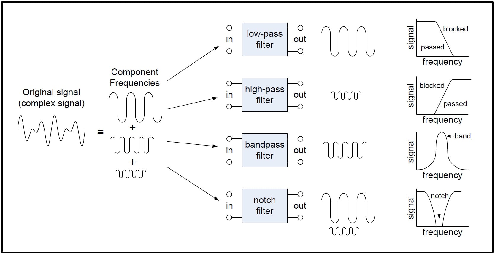
Figure 1. A basic depiction of the four major filter types.
There is also such a thing as an all-pass filter but I'm not considering it to be one of the four basic filter types for the purposes of this article.
Passive and Active Filters
Filters can be placed in one of two categories: passive or active.
Passive filters include only passive components—resistors, capacitors, and inductors. In contrast, active filters use active components, such as op-amps, in addition to resistors and capacitors, but not inductors.
Passive filters are most responsive to a frequency range from roughly 100 Hz to 300 MHz. The limitation on the lower end is a result of the fact that at low frequencies the inductance or capacitance would have to be quite large. The upper-frequency limit is due to the effect of parasitic capacitances and inductances. Careful design practices can extend the use of passive circuits well into the gigahertz range.
Active filters are capable of dealing with very low frequencies (approaching 0 Hz), and they can provide voltage gain (passive filters cannot). Active filters can be used to design high-order filters without the use of inductors; this is important because inductors are problematic in the context of integrated-circuit manufacturing techniques. However, active filters are less suitable for very-high-frequency applications because of amplifier bandwidth limitations. Radio-frequency circuits must often utilize passive filters.
Some Key Points and Terms
Response curves are used to describe how a filter behaves. A response curve is simply a graph showing an attenuation ratio (VOUT / VIN) versus frequency (see Figure 2 below). Attenuation is commonly expressed in units of decibels (dB). Frequency can be expressed in two forms: either the angular form ω (units are rad/s) or the more common form of f (units of Hz, i.e., cycles per second). These two forms are related by ω = 2πf. Finally, filter response curves may be plotted in linear-linear, log-linear, or log-log form. The most common approach is to have decibels on the y-axis and logarithmic frequency on the x-axis.
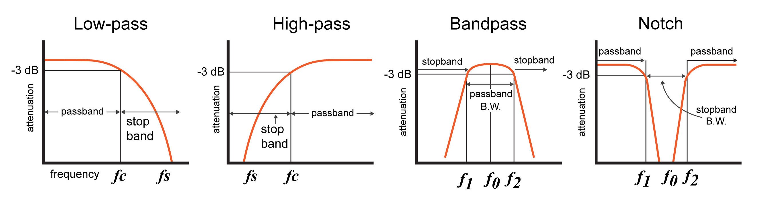
Figure 2. Response curves for the four major filter types.
Note: A notch filter is a bandstop filter with a narrow bandstop bandwidth. Notch filters are used to attenuate a narrow range of frequencies.
Below are some technical terms that are commonly used when describing filter response curves:
- -3dB Frequency (f3dB). This term, pronounced "minus 3dB frequency", corresponds to the input frequency that causes the output signal to drop by -3dB relative to the input signal. The -3dB frequency is also referred to as the cutoff frequency, and it is the frequency at which the output power is reduced by one-half (which is why this frequency is also called the "half-power frequency"), or at which the output voltage is the input voltage multiplied by 1/√2 . For low-pass and high-pass filters there is only one -3dB frequency. However, there are two -3dB frequencies for band-pass and notch filters—these are normally referred to as f1 and f2.
- Center frequency (f0). The center frequency, a term used for band-pass and notch filters, is a central frequency that lies between the upper and lower cutoff frequencies. The center frequency is commonly defined as either the arithmetic mean (see equation below) or the geometric mean of the lower cutoff frequency and the upper cutoff frequency.
- Bandwidth (β or B.W.). The bandwidth is the width of the passband, and the passband is the band of frequencies that do not experience significant attenuation when moving from the input of the filter to the output of the filter.
- Stopband frequency (fs). This is a particular frequency at which the attenuation reaches a specified value.
- For low-pass and high-pass filters, frequencies beyond the stopband frequency are referred to as the stopband.
- For band-pass and notch filters, two stopband frequencies exist. The frequencies between these two stopband frequencies are referred to as the stopband.
- Quality factor (Q): The quality factor of a filter conveys its damping characteristics. In the time domain, damping corresponds to the amount of oscillation in the system’s step response. In the frequency domain, higher Q corresponds to more (positive or negative) peaking in the system’s magnitude response. For a bandpass or notch filter, Q represents the ratio between the center frequency and the -3dB bandwidth (i.e., the distance between f1 and f2).
- For both band-pass and notch filters:
Q = f0 /(f2 - f1)
Conclusion
Filters serve a critical role in many common applications. Such applications include power supplies, audio electronics, and radio communications. Filters can be active or passive, and the four main types of filters are low-pass, high-pass, band-pass, and notch/band-reject (though there are also all-pass filters).
Resonant Filters
the filter designs we’ve concentrated on have employed either capacitors or inductors, but never both at the same time. We should know by now that combinations of L and C will tend to resonate, and this property can be exploited in designing band-pass and band-stop filter circuits.
Series LC circuits give minimum impedance at resonance, while parallel LC (“tank”) circuits give maximum impedance at their resonant frequency. Knowing this, we have two basic strategies for designing either band-pass or band-stop filters.
For band-pass filters, the two basic resonant strategies are this: series LC to pass a signal (Figure below),
or parallel LC (Figure below) to short a signal. The two schemes will be contrasted and simulated here:
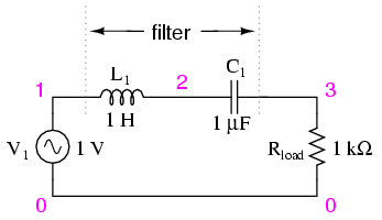
Series LC components pass signal at resonance, and block signals of any other frequencies from getting to the load. (Figure below)
series resonant bandpass filter
v1 1 0 ac 1 sin
l1 1 2 1
c1 2 3 1u
rload 3 0 1k
.ac lin 20 50 250
.plot ac v(3)
.end

A couple of points to note: see how there is virtually no signal attenuation within the “pass band” (the range of frequencies near the load voltage peak), unlike the band-pass filters made from capacitors or inductors alone. Also, since this filter works on the principle of series LC resonance, the resonant frequency of which is unaffected by circuit resistance, the value of the load resistor will not skew the peak frequency. However, different values for the load resistor will change the “steepness” of the Bode plot (the “selectivity” of the filter).
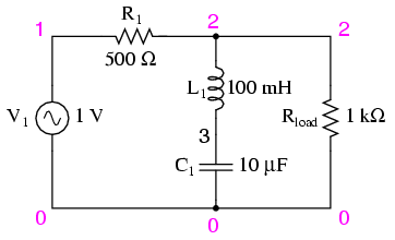
The other basic style of resonant band-pass filters employs a tank circuit (parallel LC combination) to short out signals too high or too low in frequency from getting to the load: (Figure below)

The tank circuit will have a lot of impedance at resonance, allowing the signal to get to the load with minimal attenuation. Under or over resonant frequency, however, the tank circuit will have a low impedance, shorting out the signal and dropping most of it across series resistor R1. (Figure below)
parallel resonant bandpass filter
v1 1 0 ac 1 sin
r1 1 2 500
l1 2 0 100m
c1 2 0 10u
rload 2 0 1k
.ac lin 20 50 250
.plot ac v(2)
.end

Just like the low-pass and high-pass filter designs relying on a series resistance and a parallel “shorting” component to attenuate unwanted frequencies, this resonant circuit can never provide full input (source) voltage to the load. That series resistance will always be dropping some amount of voltage so long as there is a load resistance connected to the output of the filter.
It should be noted that this form of band-pass filter circuit is very popular in analog radio tuning circuitry, for selecting a particular radio frequency from the multitudes of frequencies available from the antenna. In most analog radio tuner circuits, the rotating dial for station selection moves a variable capacitor in a tank circuit.

The variable capacitor and air-core inductor shown in Figure above photograph of a simple radio comprise the main elements in the tank circuit filter used to discriminate one radio station’s signal from another.
Just as we can use series and parallel LC resonant circuits to pass only those frequencies within a certain range, we can also use them to block frequencies within a certain range, creating a band-stop filter. Again, we have two major strategies to follow in doing this, to use either series or parallel resonance. First, we’ll look at the series variety: (Figure below)
When the series LC combination reaches resonance, its very low impedance shorts out the signal, dropping it across resistor R1 and preventing its passage on to the load. (Figure below)
series resonant bandstop filter
v1 1 0 ac 1 sin
r1 1 2 500
l1 2 3 100m
c1 3 0 10u
rload 2 0 1k
.ac lin 20 70 230
.plot ac v(2)
.end

Next, we will examine the parallel resonant band-stop filter: (Figure below)

The parallel LC components present a high impedance at resonant frequency, thereby blocking the signal from the load at that frequency. Conversely, it passes signals to the load at any other frequencies. (Figure below)
parallel resonant bandstop filter
v1 1 0 ac 1 sin
l1 1 2 100m
c1 1 2 10u
rload 2 0 1k
.ac lin 20 100 200
.plot ac v(2)
.end

Once again, notice how the absence of a series resistor makes for minimum attenuation for all the desired (passed) signals. The amplitude at the notch frequency, on the other hand, is very low. In other words, this is a very “selective” filter.
In all these resonant filter designs, the selectivity depends greatly upon the “purity” of the inductance and capacitance used. If there is any stray resistance (especially likely in the inductor), this will diminish the filter’s ability to finely discriminate frequencies, as well as introduce antiresonant effects that will skew the peak/notch frequency.
A word of caution to those designing low-pass and high-pass filters is in order at this point. After assessing the standard RC and LR low-pass and high-pass filter designs, it might occur to a student that a better, more effective design of low-pass or high-pass filter might be realized by combining capacitive and inductive elements together like Figure below.

The inductors should block any high frequencies, while the capacitor should short out any high frequencies as well, both working together to allow only low frequency signals to reach the load.
At first, this seems to be a good strategy, and eliminates the need for a series resistance. However, the more insightful student will recognize that any combination of capacitors and inductors together in a circuit is likely to cause resonant effects to happen at a certain frequency. Resonance, as we have seen before, can cause strange things to happen. Let’s plot a SPICE analysis and see what happens over a wide frequency range: (Figure below)
lc lowpass filter
v1 1 0 ac 1 sin
l1 1 2 100m
c1 2 0 1u
l2 2 3 100m
rload 3 0 1k
.ac lin 20 100 1k
.plot ac v(3)
.end

What was supposed to be a low-pass filter turns out to be a band-pass filter with a peak somewhere around 526 Hz! The capacitance and inductance in this filter circuit are attaining resonance at that point, creating a large voltage drop around C1, which is seen at the load, regardless of L2‘s attenuating influence. The output voltage to the load at this point actually exceeds the input (source) voltage! A little more reflection reveals that if L1 and C2 are at resonance, they will impose a very heavy (very low impedance) load on the AC source, which might not be good either. We’ll run the same analysis again, only this time plotting C1‘s voltage, vm(2) in Figure below, and the source current, I(v1), along with load voltage, vm(3):

Sure enough, we see the voltage across C1 and the source current spiking to a high point at the same frequency where the load voltage is maximum. If we were expecting this filter to provide a simple low-pass function, we might be disappointed by the results.
The problem is that an L-C filter has an input impedance and an output impedance which must be matched. The voltage source impedance must match the input impedance of the filter, and the filter output impedance must be matched by “rload” for a flat response. The input and output impedance is given by the square root of (L/C).
Z = (L/C)1/2
Taking the component values from (Figure below), we can find the impedance of the filter, and the required , Rg and Rload to match it.
For L= 100 mH, C= 1µF Z = (L/C)1/2=((100 mH)/(1 µF))1/2 = 316 Ω
In Figure below we have added Rg = 316 Ω to the generator, and changed the load Rload from 1000 Ω to 316 Ω. Note that if we needed to drive a 1000 Ω load, the L/C ratio could have been adjusted to match that resistance.
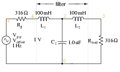
LC matched lowpass filter
V1 1 0 ac 1 SIN
Rg 1 4 316
L1 4 2 100m
C1 2 0 1.0u
L2 2 3 100m
Rload 3 0 316
.ac lin 20 100 1k
.plot ac v(3)
.end
Figure below shows the “flat” response of the L-C low pass filter when the source and load impedance match the filter input and output impedances.

The point to make in comparing the response of the unmatched filter (Figure above) to the matched filter (Figure above) is that variable load on the filter produces a considerable change in voltage. This property is directly applicable to L-C filtered power supplies– the regulation is poor. The power supply voltage changes with a change in load. This is undesirable.
This poor load regulation can be mitigated by a swinging choke. This is a choke, inductor, designed to saturate when a large DC current passes through it. By saturate, we mean that the DC current creates a “too” high level of flux in the magnetic core, so that the AC component of current cannot vary the flux. Since induction is proportional to dΦ/dt, the inductance is decreased by the heavy DC current. The decrease in inductance decreases reactance XL. Decreasing reactance, reduces the voltage drop across the inductor; thus, increasing the voltage at the filter output. This improves the voltage regulation with respect to variable loads.
Despite the unintended resonance, low-pass filters made up of capacitors and inductors are frequently used as final stages in AC/DC power supplies to filter the unwanted AC “ripple” voltage out of the DC converted from AC. Why is this, if this particular filter design possesses a potentially troublesome resonant point?
The answer lies in the selection of filter component sizes and the frequencies encountered from an AC/DC converter (rectifier). What we’re trying to do in an AC/DC power supply filter is separate DC voltage from a small amount of relatively high-frequency AC voltage. The filter inductors and capacitors are generally quite large (several Henrys for the inductors and thousands of µF for the capacitors is typical), making the filter’s resonant frequency very, very low. DC of course, has a “frequency” of zero, so there’s no way it can make an LC circuit resonate. The ripple voltage, on the other hand, is a non-sinusoidal AC voltage consisting of a fundamental frequency at least twice the frequency of the converted AC voltage, with harmonics many times that in addition. For plug-in-the-wall power supplies running on 60 Hz AC power (60 Hz United States; 50 Hz in Europe), the lowest frequency the filter will ever see is 120 Hz (100 Hz in Europe), which is well above its resonant point. Therefore, the potentially troublesome resonant point in a such a filter is completely avoided.
The following SPICE analysis calculates the voltage output (AC and DC) for such a filter, with series DC and AC (120 Hz) voltage sources providing a rough approximation of the mixed-frequency output of an AC/DC converter.
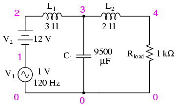
ac/dc power supply filter
v1 1 0 ac 1 sin
v2 2 1 dc
l1 2 3 3
c1 3 0 9500u
l2 3 4 2
rload 4 0 1k
.dc v2 12 12 1
.ac lin 1 120 120
.print dc v(4)
.print ac v(4)
.end
v2            v(4)
1.200E+01     1.200E+01   DC voltage at load = 12 volts

freq          v(4)
1.200E+02     3.412E-05   AC voltage at load = 34.12 microvolts
With a full 12 volts DC at the load and only 34.12 µV of AC left from the 1 volt AC source imposed across the load, this circuit design proves itself to be a very effective power supply filter.
The lesson learned here about resonant effects also applies to the design of high-pass filters using both capacitors and inductors. So long as the desired and undesired frequencies are well to either side of the resonant point, the filter will work OK. But if any signal of significant magnitude close to the resonant frequency is applied to the input of the filter, strange things will happen!
- REVIEW:
- Resonant combinations of capacitance and inductance can be employed to create very effective band-pass and band-stop filters without the need for added resistance in a circuit that would diminish the passage of desired frequencies.

the formula above to search for frequency signals on radio and TV receivers .
As lengthy as this chapter has been up to this point, it only begins to scratch the surface of filter design. A quick perusal of any advanced filter design textbook is sufficient to prove my point. The mathematics involved with component selection and frequency response prediction is daunting to say the least—well beyond the scope of the beginning electronics student. It has been my intent here to present the basic principles of filter design with as little math as possible, leaning on the power of the SPICE circuit analysis program to explore filter performance. The benefit of such computer simulation software cannot be understated, for the beginning student or for the working engineer.
Circuit simulation software empowers the student to explore circuit designs far beyond the reach of their math skills. With the ability to generate Bode plots and precise figures, an intuitive understanding of circuit concepts can be attained, which is something often lost when a student is burdened with the task of solving lengthy equations by hand. If you are not familiar with the use of SPICE or other circuit simulation programs, take the time to become so! It will be of great benefit to your study. To see SPICE analyses presented in this book is an aid to understanding circuits, but to actually set up and analyze your own circuit simulations is a much more engaging and worthwhile endeavor as a student.
Electronic filter
Electronic filters are circuits which perform signal processing functions, specifically to remove unwanted frequency components from the signal, to enhance wanted ones, or both. Electronic filters can be:
- passive or active
- analog or digital
- high-pass, low-pass, band-pass, band-stop (band-rejection; notch), or all-pass.
- discrete-time (sampled) or continuous-time
- linear or non-linear
- infinite impulse response (IIR type) or finite impulse response (FIR type)
The most common types of electronic filters are linear filters, regardless of other aspects of their design.
The oldest forms of electronic filters are passive analog linear filters, constructed using only resistors and capacitors or resistors and inductors. These are known as RC and RL single-pole filters respectively. However, these simple filters have very limited uses. Multipole LC filters provide greater control of response form, bandwidth and transition bands. The first of these filters was the constant k filter, invented by George Campbell in 1910. Campbell's filter was a ladder network based on transmission line theory. Together with improved filters by Otto Zobel and others, these filters are known as image parameter filters. A major step forward was taken by Wilhelm Cauer who founded the field of network synthesis around the time of World War II. Cauer's theory allowed filters to be constructed that precisely followed some prescribed frequency function.
Classification by technology
Passive filters
Passive implementations of linear filters are based on combinations of resistors (R), inductors (L) and capacitors (C). These types are collectively known as passive filters, because they do not depend upon an external power supply and/or they do not contain active components such as transistors.
Inductors block high-frequency signals and conduct low-frequency signals, while capacitors do the reverse. A filter in which the signal passes through an inductor, or in which a capacitor provides a path to ground, presents less attenuation to low-frequency signals than high-frequency signals and is therefore a low-pass filter. If the signal passes through a capacitor, or has a path to ground through an inductor, then the filter presents less attenuation to high-frequency signals than low-frequency signals and therefore is a high-pass filter. Resistors on their own have no frequency-selective properties, but are added to inductors and capacitors to determine the time-constants of the circuit, and therefore the frequencies to which it responds.
The inductors and capacitors are the reactive elements of the filter. The number of elements determines the order of the filter. In this context, an LC tuned circuit being used in a band-pass or band-stop filter is considered a single element even though it consists of two components.
At high frequencies (above about 100 megahertz), sometimes the inductors consist of single loops or strips of sheet metal, and the capacitors consist of adjacent strips of metal. These inductive or capacitive pieces of metal are called stubs.
Single element types

The simplest passive filters, RC and RL filters, include only one reactive element, except hybrid LC filter which is characterized by inductance and capacitance integrated in one element.
L filter
An L filter consists of two reactive elements, one in series and one in parallel.
T and π filters


Three-element filters can have a 'T' or 'π' topology and in either geometries, a low-pass, high-pass, band-pass, or band-stop characteristic is possible. The components can be chosen symmetric or not, depending on the required frequency characteristics. The high-pass T filter in the illustration, has a very low impedance at high frequencies, and a very high impedance at low frequencies. That means that it can be inserted in a transmission line, resulting in the high frequencies being passed and low frequencies being reflected. Likewise, for the illustrated low-pass π filter, the circuit can be connected to a transmission line, transmitting low frequencies and reflecting high frequencies. Using m-derived filter sections with correct termination impedances, the input impedance can be reasonably constant in the pass band.
Multiple element types
Multiple element filters are usually constructed as a ladder network. These can be seen as a continuation of the L,T and π designs of filters. More elements are needed when it is desired to improve some parameter of the filter such as stop-band rejection or slope of transition from pass-band to stop-band.
Active filters
Active filters are implemented using a combination of passive and active (amplifying) components, and require an outside power source. Operational amplifiers are frequently used in active filter designs. These can have high Q factor, and can achieve resonancewithout the use of inductors. However, their upper frequency limit is limited by the bandwidth of the amplifiers.
Other filter technologies
There are many filter technologies other than lumped component electronics. These include digital filters, crystal filters, mechanical filters, surface acoustic wave (SAW) filters, bulk acoustic wave (BAW) filters, garnet filters, and atomic filters (used in atomic clocks).
The transfer function
The transfer function of a filter is the ratio of the output signal to that of the input signal as a function of the complex frequency :


with .

The transfer function of all linear time-invariant filters, when constructed of discrete components, will be the ratio of two polynomials in , i.e. a rational function of . The order of the transfer function will be the highest power of encountered in either the numerator or the denominator.
Classification by topology
Electronic filters can be classified by the technology used to implement them. Filters using passive filter and active filter technology can be further classified by the particular electronic filter topology used to implement them.
Any given filter transfer function may be implemented in any electronic filter topology.
Some common circuit topologies are:
- Cauer topology – passive
- Sallen–Key topology – active
- Multiple feedback topology – active
- State variable topology – active
- Biquadratic topology – active
Classification by design methodology
| Linear analog electronic filters |
|---|
Historically, linear analog filter design has evolved through three major approaches. The oldest designs are simple circuits where the main design criterion was the Q factor of the circuit. This reflected the radio receiver application of filtering as Q was a measure of the frequency selectivity of a tuning circuit. From the 1920s filters began to be designed from the image point of view, mostly being driven by the requirements of telecommunications. After World War II the dominant methodology was network synthesis. The higher mathematics used originally required extensive tables of polynomial coefficient values to be published but modern computer resources have made that unnecessary.[3]
Direct circuit analysis
Low order filters can be designed by directly applying basic circuit laws such as Kirchhoff's laws to obtain the transfer function. This kind of analysis is usually only carried out for simple filters of 1st or 2nd order.

Image impedance analysis
This approach analyses the filter sections from the point of view of the filter being in an infinite chain of identical sections. It has the advantages of simplicity of approach and the ability to easily extend to higher orders. It has the disadvantage that accuracy of predicted responses relies on filter terminations in the image impedance, which is usually not the case.


Network synthesis
The network synthesis approach starts with a required transfer function and then expresses that as a polynomial equation of the input impedance of the filter. The actual element values of the filter are obtained by continued-fraction or partial-fraction expansions of this polynomial. Unlike the image method, there is no need for impedance matching networks at the terminations as the effects of the terminating resistors are included in the analysis from the start.
Here is an image comparing Butterworth, Chebyshev, and elliptic filters. The filters in this illustration are all fifth-order low-pass filters. The particular implementation – analog or digital, passive or active – makes no difference; their output would be the same.
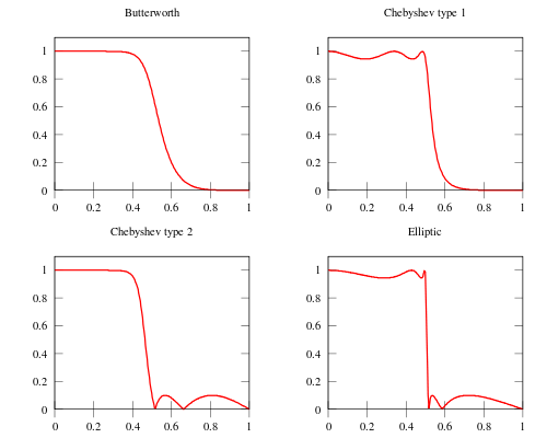

As is clear from the image, elliptic filters are sharper than all the others, but they show ripples on the whole bandwidth.
An Introduction to Audio Electronics: Sound, Microphones, Speakers, and Amplifiers
The Basics of Sound
Before discussing the specific components of audio-related circuits and electronics, let's first take a crash course on the basic concepts of sound.
Sound is simply a type of energy vibrating through a medium (such as air or water); this energy, within a specific range of frequencies, is interpreted by the human ear as sound.
Sound is made up of three basic elements:
- Frequency: how fast the vibrations are occurring
- Intensity: how loud the sound is
- Timbre: the sound's quality
The human ear can detect sound frequencies ranging from 20 to 20,000 Hz. However, the human ear is more sensitive to (i.e. able to discern at lowest intensity) frequencies ranging between 2,000 and 5,000 Hz (see Hearing Range - Wikipedia). Recall that Hertz (Hz) is a unit defined as cycles per second.
A sound's intensity corresponds to the amount of energy associated with that sound. The decibel (dB) is used for measuring the sound's energy in a way that is relevant to how humans perceive loudness.
In the context of audio, the decibel is defined as follows:
dB = 10 log10 (I/I0)
where
- I = the measured intensity (W/m2)
- I0 = 10-12 W/m2, which represents the lowest sound intensity detectable by the human ear
The figure below shows a variety of sounds and their dB intensity measurement.

Examples of sounds and their intensity (in dB). Image courtesy of ODYO Hearing Care.
Timbre is the complex wave pattern that occurs when overtones (also referred to as harmonics) are present along with the fundamental frequency. For instance, a tuning fork is designed to produce exactly one specific frequency, called the fundamental frequency. Let's say we have a tuning fork that produces a middle C note (261.62 Hz)—click here to hear middle C tuning fork. Since a tuning fork generates only one frequency, no other frequencies (overtones) exist.
However, if you were to hear a middle C played on a violin—click here to hear middle C on violin, you would hear both the fundamental frequency (261.62 Hz) and a variety of other, albeit less intense, frequencies (overtones). The specific intensity of each overtone is largely credited for giving an instrument (or a person's voice) its unique timbre (also called tonal quality).
Microphones: Dynamic, Condenser, and Electret
The microphone is responsible for converting changes in sound pressure to changes in electric current. The intensity of the changes in sound pressure corresponds to the AC voltage amplitude generated by the microphone. Likewise, the frequency of the changes in sound pressure corresponds to the frequency of the AC voltage. Obviously, if any overtones are present, they too are present in the electrical signal generated by the microphone.
Three common types of microphones are the following:
- dynamic
- condenser
- electret
The Dynamic Microphone
The dynamic microphone consists of a plastic diaphragm, a voice coil, and a permanent magnet. See figure below.
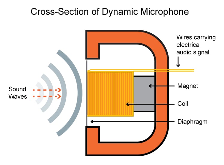
A dynamic microphone cross-section. Image adapted from MediaCollege.com
When varying sound pressure is applied to the diaphragm, the voice coil moves back and forth through the magnet's magnetic field, resulting in a voltage across the leads of the voice coil. Hence, the sound pressure is converted to a voltage signal.
Dynamic microphones are known for being very rugged, for being able to operate over a wide temperature range, for providing smooth and extended frequency response, and for not needing an external power source. They are widely used in applications such as public address and high-quality recording.
The Condenser Microphone
The condenser microphone (see figure below) uses a pair of charged plates that can be brought closer together or forced farther apart by changes in air pressure (i.e., sound). In doing so, the charged plates act like a sound-sensitive capacitor. This type of microphone works in conjunction with a low-noise, high-impedance amplifier.
Condenser microphones are known for providing crisp, low-noise sound and are used for producing high-quality sound recordings.

A condenser microphone's basic components. Image adapted from ProSoundWeb
The Electret Microphone
An electret microphone is actually a microphone and a JFET in a single package. The gate of the JFET provides a very high impedance and thus ensures that the charge on the electret element remains fixed. The charge must remain fixed to ensure that changes in capacitance (caused by sound waves) result in voltage changes. The JFET also converts the varying (gate) voltage into varying (drain-source) current. While the electret element itself does not require power (because its permanently charged) the overall electret microphone device requires a power supply because the integrated JFET needs bias current.
Older electret microphones were known to deliver poor performance, but modern devices can compete with condenser microphones.
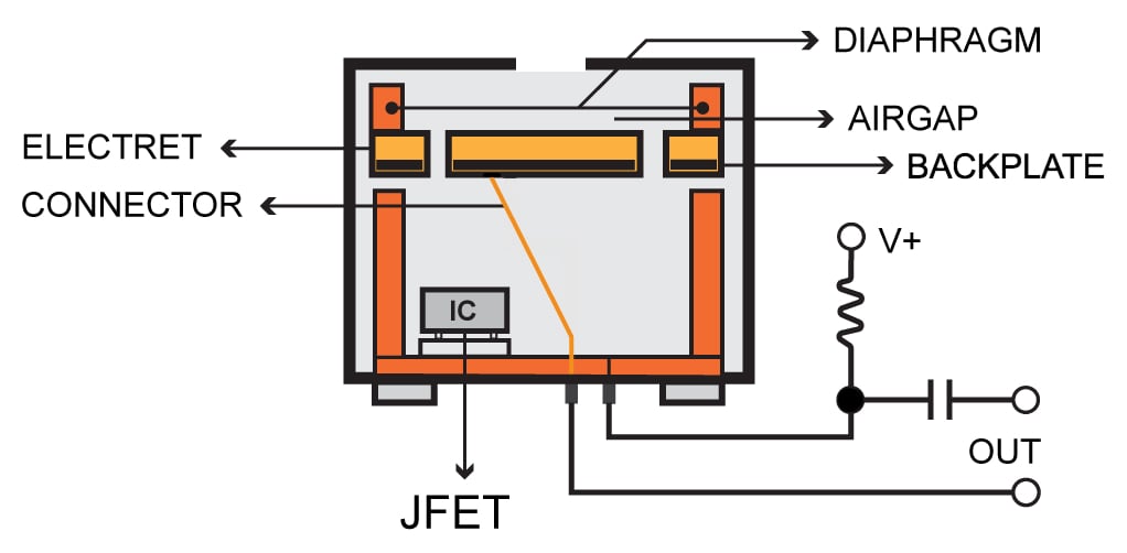
An electret microphone, Image adapted from Northwestern University.
Types of Speakers
Microphones convert sound signals into electrical signals. Speakers do the exact opposite: they convert electrical signals into audible (sound) signals.
The dynamic speaker, which uses the same operating principles as the dynamic microphone, is the most popular speaker used today. When a varying electrical signal (current) is channeled through a moveable coil (voice coil) surrounded by a magnet, the coil moves back and forth. Cones (often made of paper) attached to the moving coil then produce variations in air pressure (i.e., sound waves) that correspond to the electrical signal driven through the speaker coil.

Parts of a dynamic speaker. Image courtesy of the Virtual Institute of Applied Science
Every speaker has a nominal resistance—or, more accurately, an impedance—that represents the average resistance between the speaker leads. Thus, speakers behave similarly to resistors when placed in series and in parallel. See the figure below.
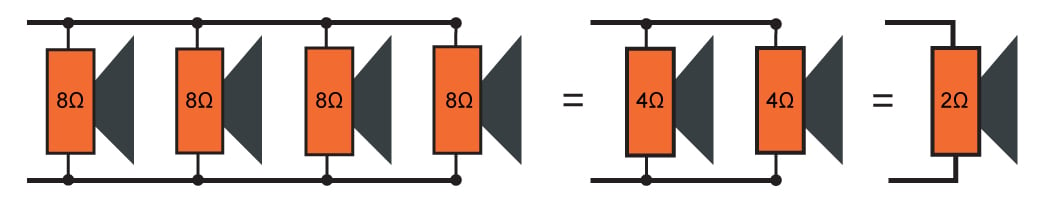
Speakers in parallel behave the same as resistors in parallel.
Frequency response, an important speaker characteristic, represents the frequency range over which a speaker can successfully propagate sound waves.
Speakers can be categorized according to the frequency range that they are designed for:
- Woofers: speakers designed specifically for low frequencies (less than 200 Hz)
- Midrange: speakers designed to accommodate frequencies ranging from 500 Hz to 3000 Hz
- Tweeter: a dedicated speaker type specifically designed to handle frequencies above those of midrange speakers
- Full-range speakers: capable of handling frequencies ranging from 100 Hz to 15,000 Hz
Full-range speakers have inferior sound qualities when compared to a sound system consisting of woofers, midrange speakers, and tweeters. Such a three-way speaker system is illustrated below.

A typical three-way speaker system consisting of a tweeter, a midrange speaker, and a woofer. Image adapted from Georgia State University
Amplifiers 101
Audio amplifier have three types of classification:
- Preamplifier
- Low-power amplifier
- Power amplifier
An audio preamplifier (often shortened to "pre-amp") is an electronic device that amplifies a very weak signal from a microphone, as an example, into signals strong enough to manipulate. Pre-amps are often simple, fixed-gain amplifiers designed specifically for low-noise performance.
A low-power amplifier is often used to manipulate signals including such aspects as volume and frequency equalization. This type of amplifier generally focuses on changing the character of the signal in desired ways while introducing as little unwanted distortion as possible and may provide little to no actual power amplification.
An audio power amplifier ("power amp") is used to increase the signal power so as to drive a load, such as output speakers. Similar to pre-amps, power amps are often fixed gain (in terms of signal amplitude) so that designers can focus on high-power gain and the power handling challenges that typically result. In simple audio systems where high power and high fidelity are not critical factors, a single-amplifier circuit may perform all of these functions, and, in fact, specially designed operational amplifiers, such as the LM-386 Low Voltage Audio Power Amplifier, are often used this way. A Class D audio amplifier is a switching or PWM amplifier where the switches are either fully ON or fully OFF, which significantly reduces the power losses. Class D amplifiers take on many different forms, including some that have digital inputs while others have analog inputs.
Conclusion
Audio electronics can be summarized as converting sound to electrical signals, processing the electrical signals, and turning these processed signals back into sound. This is a straightforward objective; nevertheless, this particular discipline of electrical engineering covers many areas of the EE world. In fact, many practicing engineers spend their entire careers researching, developing, and designing audio electronics and related equipment.

XO___XO XOXi Ping Communication And Signal Processing
Research in the Communications and Signal Processing area focuses on issues regarding the efficient processing and transmission of data. Some examples of sources of data include sound, images, and sensor output signals. Signal processing algorithms deal with efficiently transforming the signals resulting from these sources into digital data streams. Communications research focuses on efficiently transmitting streams of data from one location to another. One important example of communications research is the investigation of techniques that transmit ever increasing data rates with multiple users while consuming less radio frequency spectrum and transmitted signal power.
Digital Communications
The subject of digital communications (DCOMM) involves the transmission of information in digital form from a source that generates the information to one or more destinations. Of particular importance in the analysis and design of communication systems are the characteristics of the physical channels though which the information is transmitted.
In DCOMM, the characteristics of a channel greatly affect the design of the basic building blocks of the communication system. As such, digital communications research strives to come to a understanding about all physical elements of a communication system and its functions.
Digital Communications makes use of functions and methods such as statistical channel modeling, modulation and demodulation techniques, optimal receiver design, performance analysis techniques, source coding, quantization, and fundamentals of information theory.
Digital Signal Processing
Digital signal processing (DSP) is the study of signals in a digital representation and the processing methods of these signals. DSP and analog signal processing are subfields of signal processing. DSP has at least three major subfields: audio signal processing, digital image processing and speech processing.
Since the goal of DSP is usually to measure or filter continuous real-world analog signals, the first step is usually to convert the signal from an analog to a digital form, by using an analog to digital converter. Often, the required output signal is another analog output signal, which requires a digital to analog converter.
The algorithms required for DSP are sometimes performed using specialized computers, which make use of specialized microprocessors called digital signal processors (also abbreviated DSP). These process signals in real time and are generally purpose-designed ASICs.
Image Analysis and Computer Vision
Computer image analysis largely contains the fields of computer or machine vision, and medical imaging, and makes heavy use of pattern recognition, digital geometry, and signal processing. This field of computer science developed in the 1950s at academic institutions such as the MIT A.I. Lab, originally as a branch of artificial intelligence and robotics.
Computers are indispensable for the analysis of large amounts of data, for tasks that require complex computation, or for the extraction of quantitative information. On the other hand, the human visual cortex is an excellent image analysis apparatus, especially for extracting higher-level information, and for many applications – including medicine, security, and remote sensing – human analysts still cannot be replaced by computers. For this reason, many important image analysis tools such as edge detectors and neural networks are inspired by human visual perception models.
Computer vision is the science and technology of machines that see. As a scientific discipline, computer vision is concerned with the theory and technology for building artificial systems that obtain information from images or multi-dimensional data. Information is that which enables a decision. Since perception can be seen as the extraction of information from sensory signals, computer vision can be seen as the scientific investigation of artificial systems for perception from images or multi-dimensional data.
Computer vision can also be described as a complement (but not necessarily the opposite) of biological vision. In biological vision, the visual perception of humans and various animals are studied, resulting in models of how these systems operate in terms of physiological processes. Computer vision, on the other hand, studies and describes artificial vision systems that are implemented in software and/or hardware. Interdisciplinary exchange between biological and computer vision has proven increasingly fruitful for both fields. Applications of computer vision systems include robots and autonomous vehicles, detection, organizing information, and modeling objects.
the example e- filtering sound processing :
The vocal communication of cetaceans has been the subject of wide ranging research over recent decades, and automated mathematical analysis of vocalizations has long been a desired tool in the research repertoire. The ability to record calls in the wild and then to computerize their processing (either in real time or retrospectively in the laboratory) would greatly reduce time and budgetary burdens as well as reduce potential human observer bias and fatigue. However, existing automatic algorithms have been only partially successful in achieving these aims. Dolphins and whales produce a wide range of tonal and broadband calls; this complicates the challenge of developing automated techniques. In addition, the goals of the automated analysis of cetacean vocalizations need to be clearly specified, as a number of distinct aims exist, and each requires rather different characteristics for a successful algorithm. Automatic analysis of recordings of cetacean vocalizations can be intended to assess wild population parameters such as species identity .
++++++++++++++++++++++++++++++++++++++++++++++++++++++++++++++++++++++++
e- Filtering for e- Purification Performance Subject and Object
+++++++++++++++++++++++++++++++++++++++++++++++++++++++++++++++++++++++++
Tidak ada komentar:
Posting Komentar