:max_bytes(150000):strip_icc():format(webp)/GettyImages-548557389-57b6fe605f9b58cdfd7bca3f.jpg)


The electronics industry for mobile phone equipment is currently very developed especially in the component and applied fields in mobile phones, namely components that have been reduced or SMD components (surface mount devices) as well as SMT (surface mount Technology). the working system of a cellphone although small and dynamic but can cover a variety of menus can be an interactive tool or smart television as well as video calls and information from the internet besides its main function as a mobile telephone and two-way communication device. Next we will discuss how a modern mobile phone works, especially we can see the function of the signal system and block diagram in the development towards e-Super Block Function. Features of mobile phones at this time have been very dynamic with so many automatic sensor sensors as well as power systems that can be charged and controlled discharges of computers both wirelessly and e-Gold and Chopper cables.
There are many styles and brands of mobile phones and other handheld devices available, from simple two-way voice-enabled phones to extravagant handheld computers that also can serve as a phone. Because of the variety in designs and functions in these devices, a comprehensive list of every one of their capabilities might be longer and more extensive than would be practical, but a basic summary of the most common functions of mobile phones includes voice communication, data and some other common applications.
Voice and Traditional Phone Functions
The primary function of a mobile phone is voice communication. Like traditional landline phones, mobile phones allow one user to call another and talk from afar. Functions related to voice communications include automatic redial, last number recall, caller ID, logging of incoming and outgoing calls, speakerphone or hands-free capabilities, and speed dialing. Some phones also are equipped with voice-activated dialing and features like a silent mode, which disables ringing or indicates incoming calls and alerts by vibration. Many mobile phones also feature the ability to block calls from unwanted numbers or customize ringtones to send an audible indication of the source of an incoming call.
Data Functions
In addition to voice functions, most modern mobile phones offer some degree of text or data transfer as well. Users can send brief, typed messages to other mobile phones, share files such as pictures and video or access the internet through the use of integrated Web browsers and other Internet applications optimized to function with a small screen.
The Computer Revolution/Networks/Digital and Analog Cell Phones
Digital Cellphones
"Digital cell phones are the second generation (2G) of cellular technology. They use the same radio technology as analog phones, but they use it in a different way. Analog systems do not fully utilize the signal between the phone and the cellular network -- analog signals cannot be compressed and manipulated as easily as a true digital signal. This is the reason why many cable companies are switching to digital -- so they can fit more channels within a given bandwidth. It is amazing how much more efficient digital systems can be. Digital phones convert your voice into binary information (1s and 0s) and then compress it (see How Analog-Digital Recording Works for details on the conversion process). This compression allows between three and 10 digital cell-phone calls to occupy the space of a single analog call.
Many digital cellular systems rely on frequency-shift keying (FSK) to send data back and forth over AMPS. FSK uses two frequencies, one for 1s and the other for 0s, alternating rapidly between the two to send digital information between the cell tower and the phone. Clever modulation and encoding schemes are required to convert the analog information to digital, compress it and convert it back again while maintaining an acceptable level of voice quality. All of this means that digital cell phones have to contain a lot of processing power."
retrieved from http://electronics.howstuffworks.com/cell-phone5.htm on Feb 27, 2007
Digital cellphones can run on 4 different networks and they are: TDMA, FDMA, GSM, CDMA and how they work can be found from this link http://electronics.howstuffworks.com/cell-phone7.htm.
The digital phone has revolutionized from second generation (2G) to (2.5) and to what is now the third generation (3G) of digital technology. These 3G digital phones possess greater capabilities and increased speed to handle new features such as video, gaming and internet connection.
Advantages of Digital Cell Phones
- better quality of sound and service
- more security, eavesdropping protection
- ability to support next generation services
- stronger battery life
- more resistant to noise
- increased capacity
Analog Cellphones
Analog was the first technology used in cell phones and uses a range of frequencies, 832; two frequencies made up a channel. 30kHz was determined to be the width of the analog voice channel because it provided the closest quality to that of a landline. Each carrier has 395 voice channels and 21 data channels. While innovative at the time they are accompanied by numerous disadvantages. The battery life and talk time is short, they are more susceptible to dropped calls and interference due to outside noise, analog is unable to provide much of the multimedia characteristics of digital phones and they require larger sources of power and therefore have a high frequency of interacting and disrupting medical devices. One of the positives of analog technology is that the coverage is superior to that of digital, in the US 95% of the country is compatible with analog. As digital cell phone technology increases, analog will become extinct due to every disadvantage of analog being solved through digital with few new draw backs .
Cell phone electronics basics
The mobile phone or cell phone as it is often called is equally important to the network in the operation of the complete cellular telecommunications network. Despite the huge numbers that are made, they still cost a significant amount to manufacture, discounts being offered to users as incentives to use a particular network. Their cost is a reflection of the complexity of the mobile phone electronics. They comprise several different areas of electronics, from radio frequency (RF) to signal processing, and general processing.
The design of a cell phone is particularly challenging. They need to offer high levels of performance, while being able to fit into a very small space, and in addition tot his the electronics circuitry needs to consume very little power so that the life between charges can be maintained.
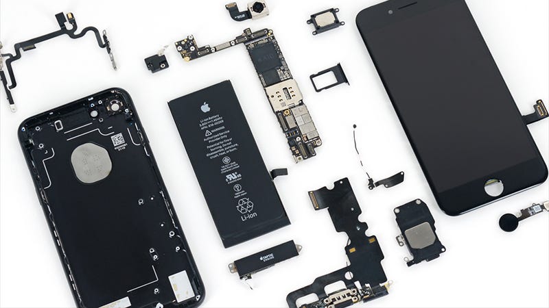
Mobile phone contents
Mobile phones contain a large amount of circuitry, each of which is carefully designed to optimise its performance. The cell phone comprises analogue electronics as well as digital circuits ranging from processors to display and keypad electronics. A mobile phone typically consists of a single board, but within this there are a number of distinct functional areas, but designed to integrate to become a complete mobile phone:
- Radio frequency - receiver and transmitter
- Digital signal processing
- Analogue / digital conversion
- Control processor
- SIM or USIM card
- Power control and battery
Radio frequency elements
The radio frequency section of the mobile phone is one of the crucial areas of the cell phone design. This area of the mobile phone contains all the transmitter and receiver circuits. Normally direct conversion techniques are generally used in the design for the mobile phone receiver.
The signal output from the receiver is applied to what is termed an IQ demodulator. Here the data in the form of "In-phase" and "Quadrature" components is applied to the IQ demodulator and the raw data extracted for further processing by the phone.
On the transmit side one of the key elements of the circuit design is to keep the battery consumption to a minimum. For GSM this is not too much of a problem. The modulation used is Gaussian Minimum Shift Keying. This form of signal does not incorporate amplitude variations and accordingly it does not need linear amplifiers. This is a distinct advantage because non linear RF amplifiers are more efficient than linear RF amplifiers.
Unfortunately EDGE uses eight point phase shift keying (8PSK) and this requires a linear RF amplifier. As linear amplifiers consume considerably more current this is a distinct disadvantage. To overcome this problem the design for the mobile phone is organised so that phase information is added to the signal at an early stage of the transmitter chain, and the amplitude information is added at the final amplifier.
Analogue to Digital Conversion
Another crucial area of any mobile phone design is the circuitry that converts the signals between analogue and digital formats that are used in different areas. The radio frequency sections of the design use analogue techniques, whereas the processing is all digital.
The digital / analogue conversion circuitry enables the voice to be converted either from analogue or to digital a digital format for the send path, but also between digital and analogue for the receive path. It also provides functions such as providing analogue voltages to steer the VCO in the synthesizer as well as monitoring of the battery voltage, especially during charging. It also provides the conversion for the audio signals to and from the microphone and earpiece so that they can interface with the digital signal processing functions.
Another function that may sometimes be included in this area of the mobile phone design or within the DSP is that of the voice codecs. As the voice data needs to be compressed to enable it to be contained within the maximum allowable data rate, the signal needs to be digitally compressed. This is undertaken using what is termed a codec.
There are a number of codec schemes that can be used, all of which are generally supported by the base stations. The first one to be used in GSM was known as LPC-RPE (Linear Prediction Coding - Regular Pulse Excitation). However another scheme known as AMR (Adaptive Multi-Rate) is now widely used as it enables the data rate to be further reduced when conditions permit without impairing the speech quality too much. By reducing the speech data rate, further capacity is freed up on the network.
Digital Signal Processing
The DSP components of the mobile phone design undertake all the signal processing. Processes such as the radio frequency filtering and signal conditioning at the lower frequencies are undertaken by this circuitry. In addition to this, equalisation and correction for multipath effects is undertaken in this area of the design.
Although these processors are traditionally current hungry, the current processors enable the signal processing to be undertaken in a far more power effective manner than if analogue circuits are used.
Control processor
The control processor is at the heart of the design of the phone. It controls all the processes occurring in the phone from the MMI (Man machine interface) which monitors the keypad presses and arranging for the information to be displayed on the screen. It also looks after all the other elements of the MMI including all the menus that can be found on the phone.
Another function of the control processor is to manage the interface with the mobile network base station. The software required for this is known as the protocol stack and it enables the phone to register, make and receive calls, terminate them and also handle the handovers that are needed when the phone moves from one cell to the next. Additionally the software formats the data to be transmitted into the correct format with error correction codes included. Accordingly the load on this processor can be quite high, especially when there are interactions with the network.
The protocols used to interact with the network are becoming increasingly complicated with the progression from 2G to 3G. Along with the increasing number of handset applications the load on the processor is increasing. To combat this, the design for this area of the phone circuitry often uses ARM processors. This enables high levels of processing to be achieved for relatively low levels of current drain.
A further application handled by this area of the design of the mobile phone is the monitoring the state pf the battery and control of the charging. In view of the sophisticated monitoring and control required to ensure that the battery is properly charged and the user can be informed about the level of charge left, this is an important area of the design.
Battery
Battery design and technology has moved on considerably in the last few years. This has enabled mobile phones to operate for much longer. Initially nickel cadmium cells were used, but these migrated to nickel-metal-hydride cells and then to lithium ion cells. With phones becoming smaller and requiring to operate for longer from a single charge, the capacity of the battery is very important, and all the time the performance of these cells is being improved.
Although mobile phones are one of the most commonplace pieces of electronics equipment these days, they are nevertheless complicated inside. An understanding of the mobile phone basics can often be useful when looking at the way a cellular network and cellular technology in general works.
Cellular network basics
The network forms the heart of any cellular telephone system. The cellular network fulfils many requirements. Not only does the cellular network enable calls to be routed to and from the mobile phones as well as enabling calls to be maintained as the cell phone moves from one cell to another, but it also enables other essential operations such as access to the network, billing, security and much more. To fulfil all these requirements the cellular network comprises many elements, each having its own function to complete.
The most obvious part of the cellular network is the base station. The antennas and the associated equipment often located in a container below are seen dotted around the country, and especially at the side of highways and motorways. However there is more to the network behind this, as the system needs to have elements of central control and it also needs to link in with the PSTN landline system to enable calls to be made to and from the wire based phones, or between networks.
Different cellular standards often take slightly different approaches for the cellular network required. Despite the differences between the different cellular systems, the basic concepts are very similar. Additionally cellular systems such as GSM have a well defined structure, and this means that manufacturers products can be standardised.
Basic cellular network structure
An overall cellular network contains a number of different elements from the base transceiver station (BTS) itself with its antenna back through a base station controller (BSC), and a mobile switching centre (MSC) to the location registers (HLR and VLR) and the link to the public switched telephone network (PSTN).
Of the units within the cellular network, the BTS provides the direct communication with the mobile phones. There may be a small number of base stations then linked to a base station controller. This unit acts as a small centre to route calls to the required base station, and it also makes some decisions about which of the base station is best suited to a particular call. The links between the BTS and the BSC may use either land lines of even microwave links. Often the BTS antenna towers also support a small microwave dish antenna used for the link to the BSC. The BSC is often co-located with a BTS.
The BSC interfaces with the mobile switching centre. This makes more widespread choices about the routing of calls and interfaces to the land line based PSTN as well as the HLR and VLR.
Base transceiver station, BTS
The base transceiver station or system, BTS consists of a number of different elements. The first is the electronics section normally located in a container at the base of the antenna tower. This contains the electronics for communicating with the mobile handsets and includes radio frequency amplifiers, radio transceivers, radio frequency combiners, control, communication links to the BSC, and power supplies with back up.
The second part of the BTS is the antenna and the feeder to connect the antenna to the base transceiver station itself. These antennas are visible on top of masts and tall buildings enabling them to cover the required area. Finally there is the interface between the base station and its controller further up the network. This consists of control logic and software as well as the cable link to the controller.
BTSs are set up in a variety of places. In towns and cities the characteristic antennas are often seen on the top of buildings, whereas in the country separate masts are used. It is important that the location, height, and orientation are all correct to ensure the required coverage is achieved. If the antenna is too low or in a poor location, there will be insufficient coverage and there will be a coverage "hole". Conversely if the antenna is too high and directed incorrectly, then the signal will be heard well beyond the boundaries of the cell. This may result in interference with another cell using the same frequencies.
The antennas systems used with base stations often have two sets of receive antennas. These provide what is often termed diversity reception, enabling the best signal to be chosen to minimise the effects of multipath propagation. The receiver antennas are connected to low loss cable that routes the signals down to a multicoupler in the base station container. Here a multicoupler splits the signals out to feed the various receivers required for all the RF channels. Similarly the transmitted signal from the combiner is routed up to the transmitting antenna using low loss cable to ensure the optimum transmitted signal.
Mobile switching centre (MSC)
The MSC is the control centre for the cellular system, coordinating the actions of the BSCs, providing overall control, and acting as the switch and connection into the public telephone network. As such it has a variety of communication links into it which will include fibre optic links as well as some microwave links and some copper wire cables. These enable it to communicate with the BSCs, routing calls to them and controlling them as required. It also contains the Home and Visitor Location Registers, the databases detailing the last known locations of the mobiles. It also contains the facilities for the Authentication Centre, allowing mobiles onto the network. In addition to this it will also contain the facilities to generate the billing information for the individual accounts.
In view of the importance of the MSC, it contains many backup and duplicate circuits to ensure that it does not fail. Obviously backup power systems are an essential element of this to guard against the possibility of a major power failure, because if the MSC became inoperative then the whole network would collapse.
While the cellular network is not seen by the outside world and its operation is a mystery to many, the cellular network is at the very centre of the overall cellular system and the success of the whole end to end system is dependent largely on its performance.
Mobile phone network registration
On any cellular telecommunications system the way in which registration and call set-up occur needs to be carefully managed. Not only does the cellular telecommunications network need to provide quick and efficient service for its rightful customers, but it also needs to be able to offer high levels of security for the user and the network.
There are many different cellular telecommunications systems in use around the globe. Older ones are being phased out, and newer cellular systems are being introduced. Accordingly there is no single way in which registration and call set up are managed. However there are some general principles that are used, and these are illustrated here.
Basic requirements
When the mobile phone is turned on it needs to be able to communicate with the cellular telecommunications network. However the phone does not have an allocated channel, time slot or chip code (dependent upon the type of access method used). It is therefore necessary for there to be some methods or allocated means within the cellular telecommunications network, whereby a newly switched on mobile can communicate with the network and set up the standard communication.
Even if a call is not to be made instantly, the network needs to be able to communicate with the mobile to know where it is. In this way the network can route any calls through the relevant base station as the network would be soon overloaded if the notification of an incoming call had to be sent via several base stations.
Cellular registration
There are a variety of tasks that need to be undertaken when a phone is turned on. This can eb seen by the fact that it takes a few seconds from switching the phone on before it is ready for use. Part of this process is the software start-up for the phone, but the majority comes from the registration process with the cellular network. There are several aspects to the regristration. The first is to make contact with the base station, and next the mobile has to register to allow it to have access to and use the network.
In order to make contact with the base station the mobile uses a paging or control channel. The name of this channel, and the exact way in which it works will vary from one cellular standard to the next, but it is a channel that is used that the mobile can access to indicate its presence. The message sent is often called the "attach" message. Once this has been achieved it is necessary for the mobile to register with the cellular network, and to be accepted onto it.
Network elements
It is necessary to have a register or database of users allowed to register with a given network. With mobiles often being able to access the all the channels available in a country, methods of ensuring the mobile registers with the correct network, and to ensure the account is valid are required. Additionally it is required for billing purposes. To achieve this, an entity on the network often known as the Authentication Centre (AuC) is used. The network and the mobile communicate and numbers giving the identity of the subscriber. Here the user information is checked to provide authentication and encryption parameters that verify the user's identity and ensure the confidentiality of each call protecting users and network operators from fraud.
Once accepted onto the network two further registers are normally required. These are the Home Location Register (HLR) and the Visitors Location Register (VLR). These two registers are required to keep track of the mobile so that the network knows where it is at any time so that calls can be routed to the correct base station or general area of the network. These registers are used to store the last known location of the mobile. Thus at registration the register is updated and then periodically the mobile updates its position. Even when the mobile is in what is termed its idle mode it will periodically communicate with the network to update its position and status.
When the mobile is switched off it sends a detach message. This informs the network that it is switching off, and enables the network to update the last known position for the mobile.
Cellular roaming
The two registers are required, one for mobiles for which the network is the home network, i.e. the one with whom the contract exists, and the other for visitors. If there was only one register then every time the mobile sent any message to the foreign network, this would need to be relayed back to the home network and this would require international signalling. The approach which is adopted is to send a message back to the HLR when the mobile first enters the new country saying that the mobile is in a different network and that any calls for that mobile should be forwarded to the foreign visited network.
By undergoing a registration procedure when the mobile is turned on, the cellular network is able to communicate correctly with it, provide access for outgoing calls, and also route any incoming calls to it in the most efficient manner. Registration also only allows those mobiles that have permission to access the network to communicate with it.
Cellular Handover and handoff
The concept of a cellular phone system is that it has a large number base stations covering a small area (cells), and as a result frequencies are able to be re-used. Cell phone systems also provide mobility. As a result it is a very basic requirement of the system that as the mobile handset moves out of one cell to the next, it must be possible to hand the call over from the base station of the first cell, to that of the next with no discernable disruption to the call. There are two terms for this process: cellular handover is used within Europe, whereas cellular handoff is the term used in North America.
The handover or handoff process is of major importance within any cellular telecommunications network. It is necessary to ensure it can be performed reliably and without disruption to any calls. Failure for it to perform reliably can result in dropped calls, and this is one of the key factors that can lead to customer dissatisfaction, which in turn may lead to them changing to another cellular network provider. Accordingly handover or handoff is one of the key performance indicators monitored so that a robust cellular handover / handoff regime is maintained on the cellular network.
Handover basics
Although the concept of cellular handover or cellular handoff is relatively straightforward, it is not an easy process to implement in reality. The cellular network needs to decide when handover or handoff is necessary, and to which cell. Also when the handover occurs it is necessary to re-route the call to the relevant base station along with changing the communication between the mobile and the base station to a new channel. All of this needs to be undertaken without any noticeable interruption to the call. The process is quite complicated, and in early systems calls were often lost if the process did not work correctly.
Different cellular standards handle hand over / handoff in slightly different ways. Therefore for the sake of an explanation the example of the way that GSM handles handover is given.
There are a number of parameters that need to be known to determine whether a handover is required. The signal strength of the base station with which communication is being made, along with the signal strengths of the surrounding stations. Additionally the availability of channels also needs to be known. The mobile is obviously best suited to monitor the strength of the base stations, but only the cellular network knows the status of channel availability and the network makes the decision about when the handover is to take place and to which channel of which cell.
Accordingly the mobile continually monitors the signal strengths of the base stations it can hear, including the one it is currently using, and it feeds this information back. When the strength of the signal from the base station that the mobile is using starts to fall to a level where action needs to be taken the cellular network looks at the reported strength of the signals from other cells reported by the mobile. It then checks for channel availability, and if one is available it informs this new cell to reserve a channel for the incoming mobile. When ready, the current base station passes the information for the new channel to the mobile, which then makes the change. Once there the mobile sends a message on the new channel to inform the network it has arrived. If this message is successfully sent and received then the network shuts down communication with the mobile on the old channel, freeing it up for other users, and all communication takes place on the new channel.
Under some circumstances such as when one base transceiver station is nearing its capacity, the network may decide to hand some mobiles over to another base transceiver station they are receiving that has more capacity, and in this way reduce the load on the base transceiver station that is nearly running to capacity. In this way access can be opened to the maximum number of users. In fact channel usage and capacity are very important factors in the design of a cellular network.
Types of handover / handoff
With the advent of CDMA systems where the same channels can be used by several mobiles, and where it is possible to adjacent cells or cell sectors to use the same frequency channel there are a number of different types of handover that can be performed:
- Hard handover (hard handoff)
- Soft handover (soft handoff)
- Softer handover (softer handoff)
Although all of these forms of handover or handoff enable the cellular phone to be connected to a different cell or different cell sector, they are performed in slightly different ways and are available under different conditions.
Hard handover
The definition of a hard handover or handoff is one where an existing connection must be broken before the new one is established. One example of hard handover is when frequencies are changed. As the mobile will normally only be able to transmit on one frequency at a time, the connection must be broken before it can move to the new channel where the connection is re-established. This is often termed and inter-frequency hard handover. While this is the most common form of hard handoff, it is not the only one. It is also possible to have intra-frequency hard handovers where the frequency channel remains the same.
Although there is generally a short break in transmission, this is normally short enough not to be noticed by the user.
Soft handover
The new 3G technologies use CDMA where it is possible to have neighbouring cells on the same frequency and this opens the possibility of having a form of handover or handoff where it is not necessary to break the connection. This is called soft handover or soft handoff, and it is defined as a handover where a new connection is established before the old one is released. In UMTS most of the handovers that are performed are intra-frequency soft handovers.
Softer handover
The third type of hand over is termed a softer handover, or handoff. In this instance a new signal is either added to or deleted from the active set of signals. It may also occur when a signal is replaced by a stronger signal from a different sector under the same base station. This type of handover or handoff is available within UMTS as well as CDMA2000.
Cellular handover or cellular handoff are performed by all cellular telecommunications networks, and they are a core element of the whole concept of cellular telecommunications. There are a number of requirements for the process. The first is that it occurs reliably and if it does not, users soon become dissatisfied and choose another network provider in a process known as "churn". However it needs to be accomplished in the most efficient manner. Although softer handoff is the most reliable, it also uses more network capacity. The reason for this is that it is communicating with more than one sector or base station at any given instance. Soft handover is also less efficient than hard handover, but again more reliable as the connection is never lost.
It is therefore necessary for the cellular telecommunications network provider to arrange the network to operate in the most efficient manner, while still providing the most reliable service.
Cellular Telecommunications & Cell Phone Technology
information on the basics of cellular telecommunications and cell phone or mobile phone technology
Key details and essential information about mobile phone or cellular telecommunications technology ranging from the most ercent developments in 5G mobile technology to some of the older established systems including the 2G GSM system that is still widely used.
Most popular cellular telecommunications tutorials
Cellular telecommunications technologies
- 3GPP, 3rd Generation Partnership Project
- 3G HSPA, High Speed Packet Access
- 3G LTE - Long Term Evolution
- 4G LTE Advanced
- 5G cellular system ideas and proposals
- Assisted GPS
- Basic cellular concepts
- IS-95 / cdmaOne technology
- CDMA2000 1X
- CDMA2000 1X EV-DO
- CDMA450
- Cellular conformance testing
- Cellular repeater
- Femtocells basics
- GPRS, General Packet Radio Service
- GSM EDGE
- GSM tutorial and technical overview
- Heterogeneous networks, Hetnet
- i-mode
- Major Mobile Phone Systems
- Mobile phone or cell phone history
- Mobile video
- Network optimisation
- Pacific or Personal Digital Cellular (PDC)
- Self Organising Networks, SON
- UMA - unlicensed mobile access
- UMB, Ultra Mobile Broadband
- UMTS / W-CDMA Tutorial
- Mobile backhaul
Latest news
- Anritsu Software Release Enables 5G NR Test
- Rohde & Schwarz investigates mobile infrastructure on the A9
- MBNL extends managed services deal with Ericsson
- Colombia’s first 100 per cent digital financial service launched
- App turns phone camera into a real-time 104-language translator
- Infineon and Alibaba Cloud sign MoU on Internet of Things
- More...
Private mobile radio
Analysis and case studies from industry experts
- End-to-End Assessment of Mobile Video Services
- Smart data – giving operators the edge
- Mobile World Congress 2018: trends, news, announcements
- Cellular Base Station Installation & Maintenance Challenges
- Data Driven Networks: managing mobile’s digital transformation
- Realizing the Promise of 5G: utilizing the technologies
- Dirty fibre and poor QoS – are operators about to trip on the first 5G hurdle?
- Mobile Network Metrics - what they mean
- Service assurance in virtualised networks
- 4G, 5G & IoT Predictions for 2016
The Sensors in Smartphone, and How They Work
smartphone is a remarkable feat of engineering. It’s half a dozen or more gadgets packed into a single slab. Much of it’s coolest feats are accomplished with a wide range of sensors — but what are they and what do they all actually do?
How does your phone count your steps and replace your fitness tracker? Does GPS use up your data? Which sensors should you make sure are in your next handset?
We need to know :
Accelerometer

Accelerometers handle axis-based motion sensing and can be found in fitness trackers as well as phones—they’re the reason why your smartphone can track your steps even if you haven’t bought a separate wearable.
They also tell the phone’s software which way the handset is pointing, something that’s becoming increasingly important with the arrival of augmented reality apps.
As the name kind of gives away, accelerometers measure acceleration, so the map inside Snapchat can put a cute toy car around your bitmoji when you’re driving, plus a host of other actually useful applications.
The sensor is itself made up of other sensors, including microscopic crystal structures that become stressed due to accelerative forces. The accelerometer then interprets the voltage coming from the crystals to figure out how fast your phone is moving and which direction it’s pointing in.
From switching apps from portrait to landscape, to showing your current speed in a driving app, the accelerometer is one of your phone’s most important sensors.
Gyroscope

The gyroscope helps the accelerometer out with understanding which way your phone is orientated— it adds another level of precision so those 360-degree photo spheres really look as impressive as possible.
Whenever you play a racing game on your phone and tilt the screen to steer, the gyroscope rather than the accelerometer is sensing what you’re doing, because you’re only applying small turns to the phone and not actually moving through space.
Gyroscopes aren’t exclusive to phones. They’re used in altimeters inside aircraft to determine altitude and position, for example, and to keep cameras steady on the move.
The gyroscopes inside phones don’t use wheels and gimbals like the traditional mechanical ones you might find in an old plane—instead they’re MEMS (Micro-Electro-Mechanical Systems) gyroscopes, a smaller version of the concept embedded on an electronics board so it can fit inside a phone.
The first time MEMS gyroscopes really hit it big was with the iPhone 4 in 2010. Back then, it was incredibly novel to have a phone that could detect orientation with such accuracy—nowadays, we take it for granted.
Magnetometer

Completing the triumvirate of sensors responsible for working out where a phone is in physical space is the magnetometer. Again the name gives it away—it measures magnetic fields and can thus tell you which way is north by varying its voltage output to the phone.
When you go in and out of compass mode in Apple Maps or Google Maps, that’s the magnetometer kicking in to work out which way up the map should be. It also powers standalone compass apps.
Magnetometers are found in metal detectors as well, as they can detect magnetic metals, which is why you can get metal detector apps for your smartphone.
However, the sensor doesn’t work alone for its primary purpose, which is inside mapping apps—it operates in tandem with the data coming from the phone’s accelerometer and GPS unit to figure out whereabouts you are in the world, and which way you’re pointing (very handy for those detailed navigation routes).
GPS

Ah, GPS—Global Positioning System technology—where would we be without you? Probably in a remote, muddy field, cursing the day we ditched our paper maps for the electronic equivalents.
GPS units inside phones gets a ping from a satellite up in space to figure out which part of the planet you’re standing on (or driving through). They don’t actually use any of your phone’s data, which is why you can still see your location when your phone has lost signal, even if the map tiles themselves are a blurry, low-res mess.
In fact, it connects with multiple satellites then calculates where you are based on the angles of intersection. If no satellites can be found—you’re indoors or the cloud cover is heavy—then you won’t be able to get a lock.
And while GPS doesn’t use up data, all this communicating and calculating can be a drain on your battery, which is why most battery-saving guides recommend switching GPS off. Smaller gadgets like most smartwatches don’t include it for the same reason.
GPS isn’t the only way your phone can work out where it is—distance to cell towers can also be used as a rough approximation, as Serial taught us—but if you’ve got some serious navigating to do then it’s essential. Modern-day GPS units inside smartphones actually combine GPS signals with other data, like cell signal strength, to get more accurate location readings.
The best of the rest

You’ve got plenty more sensors in your handset, though they’re perhaps not all as important as the four we’ve just mentioned. Many phones, including the iPhone, have a barometer that measures air pressure: it’s useful for everything from detecting weather changes to calculating the altitude you’re at.
The proximity sensor usually sits up near the top speaker and combines an infrared LED and light detector to work out when you have the phone up to your ear, so that screen can be switched off. The sensor emits a beam of light that gets bounced back, though it’s invisible to the human eye.
Meanwhile the ambient light sensor does exactly what you would expect, taking a measuring of the light in the room and adjusting your screen’s brightness accordingly (if indeed it’s set to auto-adjust).
Like the rest of the tech packed inside your handset, these sensors are getting smaller, smarter, and less power-hungry all the time, so just because phones five years apart both have GPS doesn’t mean they’re both going to be as accurate. Add in software tweaks and optimizations too and it’s more reason to upgrade your handset on a regular basis .
sensor sensors that work on smart phones :
1. Proximity Sensor

A proximity sensor is a sensor able to detect the presence of nearby objects without any physical is comprised of an infrared LED and an IR light detector. It is placed near the earpiece of a phone, and for a good reason – when you place the handset up to your ear, the sensor lets the system know that you're most probably in a call and that the screen has to be turned off. The sensor works by shining a beam of invisible to humans infrared light which is reflected from a nearby object and picked up by the IR detector.
2. Light sensor

A phone's light sensor is what measures how bright the ambient light is. The phone's software uses this data to adjust the display's brightness automatically – when ambient light is plentiful, the screen's brightness is pumped up, and when it is dark, the display is dimmed down. An interesting fact is that high-end Samsung Galaxy phones use an advanced light sensor that can measure white, red, green, and blue light independently. And that's not overkill. In fact, the Adapt Display feature uses this data to fine tune image representation.
3. Barometer

Higher-end phones have a built-in barometer – a sensor that can measure atmospheric pressure. Data measured by it is used to determine how high the device is above sea level, which in turn results in improved GPS accuracy.This sensor is really cool
4. Magnetometer

The digital compass that's usually based on a sensor called magnetometer provides mobile phones with a simple orientation in relation to the Earth's magnetic field. As a result, your phone always knows which way is North so it can auto rotate your digital maps depending on your physical orientation.
5.Hall Sensor:

A Hall effect sensor is a transducer that varies its output voltage in response to a magnetic field. Hall effect sensors are used for proximity switching, positioning, speed detection, and current sensing applications.
The main function of this proximity sensor is to detect how close your smartphone's screen is to your body. When you use your smartphone, it detects the position of ear with respect to screen and turns off the light of screen and saves battery. Also proximity sensor stops the accidental touch, unwanted input during talk. This sensor also detects the signal strength, interference sources and amplify or filter by use of Beam Forming Technique. Thus, in a nutshell, proximity sensor detect the presence of body like cheek, face or ear and stops the web surfing, music or video during talk/calling and save the battery. After the conversation, it resumes the same function which was stopped earlier during talk.
Animated Hall effect

6.Accelerometers:
Accelerometers (Gravity Sensors)are devices that can measure acceleration (the rate of change in velocity), but in smartphones, they're able to detect changes in orientation and tell the screen to rotate. Basically, it helps the phone know up from down.
All accelerometers have two fundamental parts:
1. A housing attachment to the object whose acceleration we want to measure.
2. A mass that, while tethered to the housing, can still move.
For example assume a spring and a heavy ball. If you move the housing up, the ball lags behind stretching the spring. If we measure how much that spring stretches, we can calculate the force of gravity.

Inside the smartphone accelerometer chip, engineers have created a tiny accelerometer out of silicon. It has, of course, a housing that's fixed to the phone, and a comb-like section that can move back and forth. That's the seismic mass equivalent to the ball. The spring in this case is the flexibility of the thin silicon tethering to the housing. Now clearly, if we can measure the motion of this central section we can detect changes in orientation.
The motion of the springs causes a change in value of capacitance which is sensed by a sensor which scales it to current signals to communicate with the brain of the smartphone.
And all of this happens in a matter of a microseconds !!
7.Gyroscope:

The gyroscope is a sensor that can provide orientation information as well, but with greater precision. Thanks to this particular sensor, Android's Photo Sphere camera feature can tell how much a phone has been rotated and in which direction. It is also used by Google's Sky Map for telling what constellation you're pointing a phone at.
8.Thermometer:

Some folks might remember that the Samsung Galaxy S4 bragged with a thermometer for measuring ambient temperature. However, there's a thermometer in pretty much any smartphone, and some handsets might have more than one of them. The difference is that they're used to monitor the temperature inside the device and its battery. If a component is detected to be overheating, the system shuts itself down to prevent damage. And speaking of the Galaxy S4, it pioneered the use of an air humidity sensor in a smartphone. Data provided by it was used in the S Health application to tell whether or not the user was in their "Comfort Zone" – one with optimal air temperature and humidity.
Sensor Availability
While sensor availability varies from device to device, it can also vary between Android versions. This is because the Android sensors have been introduced over the course of several platform releases. For example, many sensors were introduced in Android 1.5 (API Level 3), but some were not implemented and were not available for use until Android 2.3 (API Level 9). Likewise, several sensors were introduced in Android 2.3 (API Level 9) and Android 4.0 (API Level 14). Two sensors have been deprecated and replaced by newer, better sensors.
below Table summarizes the availability of each sensor on a platform-by-platform basis. Only four platforms are listed because those are the platforms that involved sensor changes. Sensors that are listed as deprecated are still available on subsequent platforms (provided the sensor is present on a device), which is in line with Android's forward compatibility policy.

Today's smartphones are incredible little machines – ones that would have been regarded as witchcraft several decades ago. But we've grown so used to our iPhones and Android handsets that take them for granted even though there's so much cool technology packed into them. Take their sensors for example. Do you know how many different kinds go inside a smartphone?
Let's start with one of the most commonly used sensors – the accelerometer. As its name implies, it measures the acceleration that the handset is experiencing relative to freefall. Move it in any direction and data from this sensor will spike, but leave it still and it will go flat. The same sensor is also used to determine a device's orientation along its three axes. Apps use this data to tell if a phone is in portrait or landscape orientation, if its screen is facing up- or downward.
The accelerometer/gyroscope sensor inside the Samsung Galaxy S5, marked in blue
The gyroscope is a sensor that can provide orientation information as well, but with greater precision. Thanks to this particular sensor, Android's Photo Sphere camera feature can tell how much a phone has been rotated and in which direction. It is also used by Google's Sky Map for telling what constellation you're pointing a phone at.
The most commonly used sensors
Accelerometer, measures the acceleration that the handset is experiencing relative to freefall, also used to determine a device's orientation along its three axes
Gyroscope is a sensor that provide orientation information with greater precision.
Magnetometer, to detect magnetic fields. (compass applications use this to point at the planet's north pole)
Proximity sensor, It is placed near the earpiece of a phone. During a call, this sensor lets the system know that you're most probably in a call and that the screen has to be turned off.
Light sensor, measures how bright the ambient light is. The phone's software uses this data to adjust the display's brightness automatically.
Barometer measures atmospheric pressure. Data measured by it is used to determine how high the device is above sea level, which in turn results in improved GPS accuracy.
Thermometer measures ambient temperature. Some handsets might have more than one of them(to monitor the temperature inside the device and its battery)
Air humidity sensor to measure the "Comfort Zone" – one with optimal air temperature and humidity.
Pedometer is a sensor used for counting the number of steps that the user has taken.
Heart rate monitor, measure one's pulse, and it does that by detecting the minute pulsations of the blood vessels inside one's finger.
Not so popular ones
Fingerprint sensors, the sensor is most convenient to use, as it does not require swiping in order to read fingerprint data.
Detecting harmful radiation: used to measure the current radiation level in the area
and then Touch screen, GPS, Cameras and Microphones can be considered as sensors as well .
A smartphone sensor is any one of a number of different types of sensing devices installed on a user's phone to gather data for various user purposes, often in conjunction with a mobile app.
Here are a few examples of smartphone sensors and their uses:
- An accelerometer detects acceleration, tilt and vibration to determine movement and orientation.
- A gyroscope identifies up/down, left/right and rotation around three axes for more complex orientation details.
- A light sensor detects data about lighting levels in the environment to adapt the display accordingly.
- A proximity sensor detects when the the phone is held to the face to make or take a call, so the touch screen display can be disabled to avoid unintended input.
- A fingerprint sensor can enable biometric verification for secure device and website authentication as well as mobile payment.
- A magnetometer detects the direction of magnetic north and, in conjunction with GPS, determines the user's location.
- An infrared sensor can be used to identify user movements for gesture recognition.
Smartphone sensors: What, Why, How
There’s an array of sensors working in tandem to make that slab of glass and metal in your hand a smartphone.
")
Apps on your phone need a lot of telemetry data from the real world to make a lot of apps work properly. (Representational image: iPhone 7)
You might have often considered why the touch screen phones of today are called smartphones. Surely, they are capable of doing tasks that were only possible on computers before their advent and have made our lives a lot easier. But, apart from that, they also manage to collect and process a lot of data in the background; the data that makes it possible for the all the other apps to work in peace.
We are not discussing the data that the OS collects and initializes to adapt to your computing habits. Apps on your phone need a lot of telemetry data from the real world to make a lot of apps work properly. Therefore, manufacturers have to embed a lot of sensors in a smartphone to help them make your life a lot easier, some of which are very important for some of the necessary services from the phone.
First of all, there’s the Accelerometer sensor which is responsible for letting the smart algorithms understand how fast you are moving towards a particular direction. The sensor consists of microscopic crystal elements that get stressed during a movement, which is then used to tell the onboard processor that how fast you are going in the real world. Thank this sensor the next time for switching the screen from portrait to landscape mode or calculating your speed on the move.
Up next is the Magnetometer sensor which detects the way you are pointing on the globe. This sensor deals with magnetic fields and alters the voltage accordingly to let Google Maps know the direction you are standing. This sensor is also the reason behind those cool compass apps that come to help while you scaling uncharted territories.
360-degree videos/photos are the fads these days and your phone’s Gyroscope sensor plays a primary role is letting you scroll through the world surrounding your VR headset. Smartphones use a Micro Electro Mechanical System (MEMS) gyroscope to help you turn your car in Asphalt 8 by simply tilting the device.
 This is how you control your souped-up racecars in smartphone games.
Your smartphone is smart enough to know your position on the globe – thanks to Global Positioning System (GPS). Without this sensor, your OLA or UBER cabs cannot figure out your location in a busy metropolitan city. GPS utilises satellites hovering a few kilometres above the earth to pinpoint your exact location on the globe. Of course, if you are inside a building or it’s raining, GPS puts it hands up as it needs clear line-of-sight communication. These days, smartphones are embedding chips that support the Russian GLONASS and Chinese Beidou apart from the American GPS.

Data security on smartphones has become a prime concern, to which a Fingerprint sensor comes to the rescue. We generally find capacitive sensors to read fingerprints, which utilises the ridges on your fingertip to alter the charge in a tiny capacitor embedded in the sensor to detect unique patterns. These days, ultrasonic sensors are also in use – they utilise ultrasonic waves to read fingerprints. Vivo has recently shown-off a concept with the ultrasonic scanner placed underneath the display.
 Vivo's ultrasonic fingerprint scanner.
You also have the Proximity sensor beside the earphones to switch off the display while you are talking to someone. This sensor utilises an infrared LED to emit infrared light which is detected by a light detector, thus collecting data for the phone to put the display to sleep.
There’s the Auto Brightness sensor that has the sole task of measuring ambient light and telling the phone to adjust the brightness accordingly so that it doesn’t feel awkward to have your face brightly lit in a dark theatre while you are checking messages.
Selected smartphones, like the iPhones and the Samsung flagships, also have the luxury of a Barometer which, as the name suggests, measures atmospheric pressure and is helpful in detecting altitude or weather changes.
Some recent smartphones from Samsung – the deceased Galaxy Note 7 and the popular Galaxy S8, have been flaunting iris scanners too. These read the iris of your eye, which is unique to an individual, for verification purposes.
 Samsung's iris scanner on the Galaxy S8.
One important fact to know is that all of the above-mentioned sensors work in tandem to keep the system working. For example, Google Maps requires all of these to help you navigate through the concrete labyrinths of today. However, with technology always gliding higher than before, we can expect more sensors to become a part of the latest smartphones. All we need to do is thank the people behind these sensors the next time we are utilizing our smart apps.

Sensors have been around since long before the smartphone. But not only did they make their way to the digital age, they are also getting smaller and smaller: The picture above shows a close-up of the intricate tech of an iPhone’s pinhead sized gyroscope.
Meanwhile, sensors are also significantly improving their accuracy. This enables your smartphone to see light and hear sound in great detail as well as picking up signals that we cannot.
And we are getting more and more creative in putting this increased perception to use. It helps to make our everyday use of technology more intuitive and opens the door to new applications. By now, your smartphone is probably also your navigation device, your camera, a gaming console and your digital wallet.
All these functions would not be possible without the microscopic sensor tech inside.
Let’s go through some of your phone’s powerful micro-sensors and see what they can do.

Motion: Accelerometer & Gyroscope
An accelerometer can detect orientation relative to gravity as well as translational motion.
Put that in your phone and you can measure tilts and translation in a linear direction to some extent. That’s how your phone knows if you are using a landscape or portrait view and can automatically adjust the screen.
To help the accelerometer out with accurate orientation, even when the phone is moving through space, its data is combined with a gyroscope. It measures changes in angular velocity.
The gyroscope is used to detect more complex orientation changes, you need for Augmented Reality apps, watching 360 degree videos or using your phone as steering wheel in a racing game.
To measure mechanical signals with digital sensors your phone uses Micro Electric Mechanical Systems (MEMS). They offer a smaller version of the concept of mechanical sensor tools embedded on an electronics board.
Here’s how it works:
Combined motion sensing with accelerometer and gyroscopes can be put to use in more complex applications. Sport and fitness apps use these sensors to track the user’s steps and combine it with GPS to show your route and pace.

Location: GPS, barometer, magnetometer
When it comes to location, the first thing that comes to mind is most likely GPS, the global positioning system. Your phone’s receiver picks up signals from a satellite network to triangulate its relative position. But since GPS signals aren’t available everywhere, more accurate positioning systems fill in the gaps with motion sensing or other sensors.
Many phones have a barometer that measures air pressure. This is useful for detecting weather changes, but in combination with other tools, like GPS, Wi-Fi and beacons, barometers can contribute altitude data to a positioning signal.
As the name indicates, a magnetometer measures magnetic fields. With the earth’s magnetic field, a magnetometer can provide your phone with a simple orientation. Digital compass apps make use of this and so do digital maps that rotate depending on your physical orientation.
But the usage of magnetometers can go beyond this: The ability to detect a magnet’s position is already working in great detail and its accuracy is improving. This paves the way for other functions like wireless gesture control.

Light & Sound: Microphones, ambient light and proximity
Microphones are not particularly new, but with Alexa, Siri and Cortana, the trend is clearly going towards voice command, giving them an increasing role in future tech.
MEMS microphones are taking over the market for smartphones since they are far smaller than any other competitor. They provide an increasingly high-definition audio quality for recordings and are standard in smart devices like smart watches or smart glasses.
Ambient light sensors can measure the light around the device. Your smartphone typically uses it to adjust the brightness level according to its environment.
The proximity sensor works in a similar way, but detects infrared light, invisible to the human eye. It is usually placed near the top speaker of your phone and combines a LED that emits an IR beam eye with a light detector. If the light gets bounced back the proximity sensor detects the reflected light.
This way it can work out whether you have the phone up to your ear or in your pocket. The screen can be switched off to save energy or disables the touch screen. Other use cases include using it as a motion detector and turn your phone into a security camera.
 Fingerprint sensors
There are multiple ways fingerprint sensors at work: optical, capacitive or ultrasonic. These scanners use light, an electrical current or an ultrasonic pulse is and transmit it against the finger.
From the information that is pinged back they can generate an image of the ridges and valleys that make up a unique fingerprint. This technology enables features like secure login to a device or authentication for mobile payment.
The picture above shows Vivo’s first in-screen fingerprint sensor, which was demonstrated at CES 2018. It uses an optical sensor, that’s peering through the gaps between the pixels of the OLED display and allows the sensor to be put on the screen and not on the back of the device, as many other competitor products.

More to come…
Mobile sensors keep getting more accurate, more compact, and more energy-efficient. And as MEMS are becoming even smaller and more sophisticated, new types of sensors will be standard features of your phone very soon.
As new and better sensors make your phone more perceptive than ever, opportunities for their potential application are unfolding: Immersive gaming experiences, indoor navigation and new security standards might be just a micrometre sensor away.
for charging problem troubleshooting for knowing which parts or components has being used to make a charging circuit. Many mobile phone technicians had been asking me, how does mobile phone charging circuit works? How does a battery charger can charge a mobile phone battery?
To tell the truth many of them has never heard of this even they already fix thousands of mobile phones in their years of cellphone repair careers.
Well, that all mobile phones are all battery operated handsets that needs to charge the battery so that it will continue working, failure to charge it will result to unable to power up the mobile phone handsets.
Here's a brief explanation of how charging circuit works,
I prepare this simple idea and diminished some electronics technical terms so that everyone without adequate knowledge on electronics technical terms might can catch up with this.

A charging circuit is composed of the following stages or sections.
1. Battery Charger Circuits - Although this is not found on mobile phones PC board circuit and have separate circuit but definitely this is also part of charging circuit; without this, the charging circuit is not complete and will not work completely.
This circuit is all parts and components that being mounted on any mobile phone charger, this is the one that converts AC (Alternating Current)voltage to DC (Direct Current)voltage.
What is AC Voltage? This voltage is a power source that we used in our household appliances to work and operate, this voltage can cause risk of electric shock and very dangerous to humans when being touch.This kind of voltage has an alternate polarity.
What is DC voltage? This voltage is a low level voltage which typically found on any kind of batteries.
This kind of voltage have two polarities, the negative and the positive.
Here's how the battery charger works, the 110 or 220 AC volts coming from the electrical outlet at home or etc. will be converted to a desired DC voltage like 4.5 to 6 volt DC because the phone only accepts and can be operated into small amount of DC voltage.

A DC voltage output of a charger is only an artificial DC voltage, why is that? because only a battery cell can produce a 100% pure DC voltage.
2. Protection Circuit- this circuit is composed of a Fuse, Inductor coil Diode and Capacitors, before the DC voltage reach to the charging voltage control circuits the protection circuit is the one that control and check if that voltage is in exact amount. Let say the desired amount of DC voltage is only 5.6 volts above that point the fuse will be blown out to stop the voltage to flow so that it prevents damaging to another corresponding circuits.
In a protection circuit below of Nokia BB5 mobile phones a diode is the one that measure the amount of voltage from the battery charger, this diode has a reaching point of desired voltage to measure of how much amount of voltage will be allowed to flow within that line, when exceed to that desired point of voltage the diode will then cut it off.

like for example if that diode is being designed that only allows only 7 volts from the battery charger to flow on that line. Now, above that desired voltage let say that the voltage becomes 8 or higher the diode will then be reacts and destruct itself, this is what then so-called shorted component; so that the current will flow directly to ground and will not reach to the following or corresponding circuit. If the diode will cut off or shorted the fuse will tends to blow and totally cut the voltage line. The inductor coil's role is to filter unwanted voltage saturation, it rejects abnormal voltage modulation caused by electrostatic interference.
3. Charger Voltage Control Circuit - This is the stage where the charger voltage and current is being stabilized, amplified, rectified, regulated and other voltage purification process is being held in this area before it feeds to the battery. This kind of circuit commonly being pack in a chips together with another circuits.
A failure of this certain area will result on charging problem status. This area mostly called by most technician as a Charging IC it is because this circuit is inside in a particular IC chips, but eventually this circuit also accompanied by many other circuit types and not exclusive to a certain charging area.

This pictures shows is the next corresponding circuit from the protection circuit area. The voltage from charger is now then feeds into three terminal inputs of the charger voltage control circuits.

in this figure shows after the voltage stabilization and purification process the voltage is now then feeds to the battery terminal.
4. Charging Control Circuit - this is the area where the charging process is being monitored, this is the one that sends information to the application processor to start or stop the charging process. This area is part of Power management circuit, so-called POWER IC by many technicians.
4. Charging Control Circuit - this is the area where the charging process is being monitored, this is the one that sends information to the application processor to start or stop the charging process. This area is part of Power management circuit, so-called POWER IC by many technicians.

In this picture that there are two terminal signal from the voltage control that sends data to the Charging control circuit, this two data signals will inform to the charging control circuit that a charger voltage is being entered or plug-in. After this charging control circuits receives the data it will then analyze and convert that data into digital signal then sends it to the Application processor.

The application processor which is the brain of all the circuits now then decide if all the data's are in correct or in right information to begin the process,
It always relies on the data that sends by the charging control circuit, then decide all data and completely process it.
Okay now lets take an example and apply this particular method on a mobile phone circuitry component layout, I have here a Nokia N95 board, which is a good way to start with, while we still working on advance training. Now, try to analyze and compare all of those previous picture above and combined them into each corresponding stages or section, in this manner you can build an step by step tracing procedure on how to deal charging problem issues.

In the picture above shows, how and where the voltage flow from a charger voltage source through the entire PC board circuit. This is the the method where you can start and manage how to locate and trace each and every component to find possible problems regarding charging problem issues.
Cell Phone Detector circuit
Cell Phone Detector is a circuit that can sense the presence of any activated cell-phone nearby and gives an indication of activated cell-phone near around of it. Basically Cell-phone detector is a Frequency Detector or a Current to Voltage Converter Circuit which catches frequencies about 0.8 - 3.0GHz (Mobile band frequencies). RL tuned circuit (Resistor–Inductor circuit) is not suitable for detecting the RF signals in GigaHertz range.
This Mobile Detector Circuit can detect incoming/outgoing calls, messaging, video transmission and any SMS or GPRS uses within the range of 1 meter. This circuit is very useful to detect Cell-phones at Cell-phone restricted places like Exam halls, meeting rooms, hospitals etc. It is also useful in detecting the unauthorised use or spying using hidden Cell Phone. It can detect the RF Transmission from the Mobile Phone and triggers Buzzer to produce beep sound, even if the phone is kept on Silent mode and this alarm continues beeping till the presence of RF signals.
Required Components:
- Op-Amp CA3130
- 2.2M resistor (2)
- 100K resistor (1)
- 1K resistor (3)
- 100nF capacitor (4)
- 22pF capacitor (2)
- 100uF capacitor
- Bread board
- 9 Volt Battery
- Battery Connector
- LED
- Transistor BC547
- Transistor BC557
- Connecting wires
- Buzzer
- Antenna
Circuit Explanation:
In this circuit we have used a CA3130 OP-Amp IC for detecting incoming or outgoing signal around it. Op-amp non-inverting end is connected to Vcc through 2.2M resistor and it is also connected to the ground through 100K resistor and 100uF Capacitor. Its inverting terminal is feedback from its output through a 2.2M resistor for amplify the signal. Two 100nF capacitors are connected between inverting and non-inverting terminal, working as loop antenna for the system. Two 100nF capacitors are connected in series between Pin 1 and 8 of op-amp to boost the gain of the current to voltage converter at its output pin.
Output of this op-amp is connected at the base of NPN transistor namely BC547 through a 1k resistor and a LED is connected at its emitter for indication. A buzzer is also used for sound indication by using a PNP transistor namely BC557. And a 9 volt battery is used for powering the circuit. Rests of connections are shown in the Circuit Diagram below.

Working Explanation:
This circuit consist an op-amp with some active passive components. A LED and buzzer are used for indication of presence of cellphone. Op-amp is configured as Frequency Detector or Current to Voltage Converter and its output is connected to a LED and buzzer using NPN and PNP transistors.
Working of Mobile Detector is simple. Two 100nF capacitors (C2 and C3), in parallel, are used for detecting RF signal from Mobile Phone. These capacitors are working as loop antenna for the system. When there is any call or SMS then capacitors in parallel detect the data transmission frequencies or RF signal and output of op-amp goes high or low (fluctuating) due to generated current at the input side of op-amp. Due to these fluctuations, LED turns on and off through NPN transistor according to the signal’s frequency. Now PNP transistor is also triggered with the same frequency and buzzer starts beeping until data transmission gets finished.
HOW ARE ANALOG AND DIGITAL PHONE SYSTEMS DIFFERENT?
First, let’s look at the basic differences between analog and digital telephone systems. Analog systems have supported businesses for decades. Built on standard copper wire and POTS (plain old telephone service) phones, they are reliable, boast good voice quality, and have the basic features you might find in a typical home phone such as hold, mute, redial, and speed dial. They may also be able to transfer calls between extensions. But their features end there. Because of their simplicity and limited potential for expansion, they are relatively inexpensive to purchase. However, analog systems, because they use less-modular hardware can be expensive to support, configure, and upgrade. For example, changing the location of an extension requires rewiring a punchboard by a professional. Buying analog is cheaper in the short-term but will lock you into a closed system that requires adapters to integrate with common applications such as VoIP and customer relationship management (CRM) systems.
Digital telephone systems are more modern. Digital PBXs are designed with a proprietary bus structure for adding features and capabilities. Boards are added to the cabinets for analog, digital, or IP phones. Features such as music on hold, VoIP integration, and alarm systems can be supported with modular add-on boards.
Today, most digital systems, even if they use proprietary hardware or protocol, offer an IP interface on the controller. The IP interface might allow unified messaging features such as voicemail delivery to email, fax delivery to email, voicemail transcription to SMS, click to dial, and a desktop client. These systems are considered “hybrid PBXs” because they use a combination of proprietary digital hardware and standards-based IP networking.
A fully modern digital PBX is 100% IP and software-based.
Since digital PBX’s do not rely on simple copper wire circuits, you gain more flexibility for adds, moves, and changes. Often those changes can be configured via point-and-click software. Voice clarity is the same or better than analog, and in addition to basic features such as extensions and transfers, digital PBXs offer advanced virtual auto attendants, voicemail and call forwarding options. Digital PBX systems may also provide an interface to integrate with your call center and sales software as well.
Michels said that the advantages of software-based telecommunications solutions are the most important difference between analog and digital systems.
“The most significant change in communications isn’t as much analog/digital/VoIP, but a shift from hardware to software-based solutions,” he said. “Software controlled solutions offer a superior upgrade path and more advanced features for integration with existing and future business systems such as CRM, messaging, and social networking.”
ANALOG VERSUS DIGITAL IN A SMALL BUSINESS
Small businesses want to control costs while enjoying the features used by large businesses. While the low initial cost of an analog system can be tempting, consider ongoing costs and limitations. Pricing has become much more competitive over the last ten years, and both analog and digital systems likely require professional installation. However, an on-premise system requires far more installation and configuration than a cloud-based phone system that uses your existing computer network.
Research is an essential step in purchasing a new phone system. Anticipate how the system features will support your operating needs. The administration of the system will likely be the responsibility of an office manager or IT professional, and a software-based digital PBX will offer an interface that is familiar and flexible.
Research is an essential step in purchasing a new phone system. Anticipate how the system features will support your operating needs. The administration of the system will likely be the responsibility of an office manager or IT professional, and a software-based digital PBX will offer an interface that is familiar and flexible.
CAN YOU INTEGRATE ANALOG AND DIGITAL?
There are many established ways to integrate analog and digital devices. An analog fax or alarm system, for example, can connect to a digital system via an analog gateway. Analog phone systems can connect to VoIP trunks via multi-port ATA adapters. Selecting the right adapter can be a challenge, as the number and types of ports are dependent on the requirements of your VoIP provider and a professional will likely be needed to install it.
Ultimately, the telephone system you choose should reflect your organization’s vision and unique needs. If you have very simple needs that a home phone system could support and anticipate your needs remaining unchanged, then an analog system may be right for you. If you want a system that will grow and evolve with your business, then go digital. A phone system for small business hosted in the cloud frees up resources to focus on the core business.
Ultimately, the telephone system you choose should reflect your organization’s vision and unique needs. If you have very simple needs that a home phone system could support and anticipate your needs remaining unchanged, then an analog system may be right for you. If you want a system that will grow and evolve with your business, then go digital. A phone system for small business hosted in the cloud frees up resources to focus on the core business.
XO__XO XI PING Is the signal from a phone analog or digital, and why?
Phones use both analog and digital signals.
Mobile phones use analog signals to send and receive a communication signal; however, the information inside that communication signal (text or speech) is actually digital.
Similarly, land phones may use analog carriers, but again, all conversations are digital.
It'll be analog until it gets converted somewhere in the network, nobody wants to handle analog signals anymore.
Is it a cell phone? The phone encodes your analog voice into a digital signal, then it is mixed with various other digital information and modulated into an “analog” waveform for radio transmission.
Ultimately all electrical signals are analog. Digital signals go from one analog voltage value to another and are then interpreted as digital 1s and 0s.
Cellphones Different From Smartphones?
A smartphone is a cellphone with advanced features, so the two terms aren't interchangeable, even if people sometimes use them that way. Technically, a smartphone is a cellphone, but a cellphone is not smart.
Smartphones Are Tiny Computers
Think of a smartphone as a miniature computer that can place and receive calls. Most smartphones connect to a virtual store with thousands of apps that turn the phone into something much smarter than a regular cellphone.
Smartphone apps include games, image editors, navigation maps, budgeting apps, word processors, and multiple web browser options. Some phones provide you with a built-in virtual assistant, such as Apple iPhone's Siri, that responds to your verbal instructions.
Cellphones place and receive voice calls and send text messages. Smartphones do those things and much, much more. How much more depends on the smartphone's operating system.
Mobile Operating Systems
A mobile operating system is much like the software that powers your personal computer at home or work, except that it's built for mobile devices. Both cellphones and smartphones have mobile operating systems.
Your computer is most likely running a Windows, macOS, or Linux operating system, but your smartphone's mobile operating system might be iOS, Android, Windows Mobile, BlackBerry OS, or WebOS, among others.
Mobile platforms work entirely differently from desktop ones because they are built with the intention that the menus and buttons be touched instead of clicked. They're also built for speed and ease of use.
A cellphone's operating system is usually bland and straightforward with minimum menus and few if any ways to customize things like the virtual keyboard. Smartphone operating systems are much more sophisticated. With the addition of apps, there is almost no limit to what you can do with a smartphone including check your email, get turn-by-turn navigation instructions, make reservations at a nearby restaurant, do your Christmas shopping on the internet and many, more things. Smartphones are easy to customize and include accessibility features so even people with physical limitations can use the phones.
Why the Differences Matter
If you only want to make and receive calls, either cellphones or smartphones can handle that function. The price on cellphones is much lower than for smartphones, which have vanquished most of the nonsmart cellphones on the market. The introduction of the first commercial smartphone—the Apple iPhone—in 2007 changed the way people communicate, and the public has embraced those changes.
XO__XO XI PING XCO Wireless Charging
Wireless charging is a technology that allows charging over (very) short distances without cables.
The advantage of wireless charging is that it’s quicker and easier, as you don’t have to plug and unplug each time – you just place your device on top of your wireless charging pad. It also looks neater.
There are various competing standards for wireless charging.
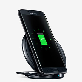
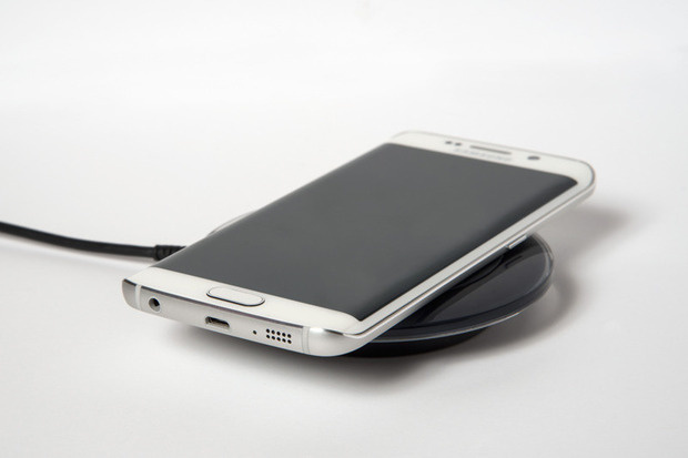
Do We need an adapter?
If your phone appears here, you need the accessory linked and a wireless charging pad.
- Apple: iPhone 7, iPhone 7 Plus, iPhone SE, iPhone 6S, iPhone 6S Plus, iPhone 5S
- Samsung: Galaxy S5, Galaxy S4, Galaxy S3, Galaxy Note 3, Galaxy Note 2
- Microsoft: Lumia 930, Lumia 925, Lumia 830
- Sony: Xperia Z3, Xperia Z2, Xperia Z
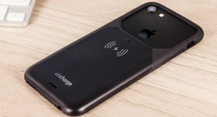
Universal wireless charging adapters
If your phone isn’t listed above, then you’ll need a universal adapter and a wireless charger. You can get these for phones with Micro USB ports (e.g. Android) and Lightning ports (e.g. iPhone).
You have a choice of an internal adapter, which slides into the back of a case, and an external adapter, which hangs outside. In most cases, we recommend internal adapters.
| Internal adapter | External adapter | |
| Micro USB (Android) | KSIX | aircharge |
| Lightning (iPhone) | Choetech | aircharge |
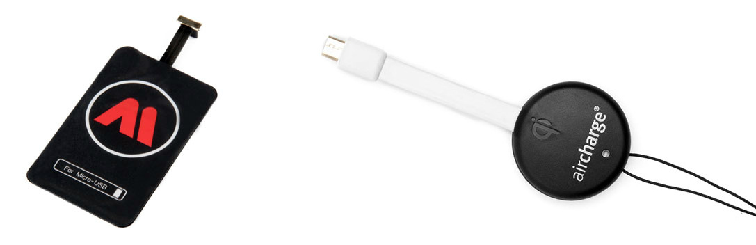
Wireless chargers
Once you’ve determined your phone has wireless charging built in or you’ve added it with an accessory, you just need a wireless charger.
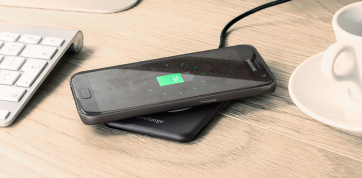
Inductive charging (also known as wireless charging or cordless charging) uses an electromagnetic field to transfer energy between two objects through electromagnetic induction. This is usually done with a charging station. Energy is sent through an inductive coupling to an electrical device, which can then use that energy to charge batteries or run the device.
Induction chargers use an induction coil to create an alternating electromagnetic field from within a charging base, and a second induction coil in the portable device takes power from the electromagnetic field and converts it back into electric current to charge the battery. The two induction coils in proximity combine to form an electrical transformer.[1][2] Greater distances between sender and receiver coils can be achieved when the inductive charging system uses resonant inductive coupling.
Recent improvements to this resonant system include using a movable transmission coil (i.e., mounted on an elevating platform or arm) and the use of other materials for the receiver coil made of silver plated copper or sometimes aluminium to minimize weight and decrease resistance due to the skin effect.

The transfer of power was the very first attempt using radio waves as a medium. Radio waves were first predicted in 1864 by James C. Maxwell. In 1888, Heinrich Hertz showed evidence of radiowaves using his spark-gap radio transmitter. a bus was produced which was powered by inductive charging, and similar work was being done in France and Germany around this time.
In 2006, MIT began using resonant coupling. They were able to transmit a large amount of power without radiation over a few meters. This proved to be better for commercial need, and it was a major step for inductive charging.
Applications of inductive charging can be divided into two broad categories: Low power and high power:
- Low power applications are generally supportive of small consumer electronic devices such as cell phones, handheld devices, some computers, and similar devices which normally charge at power levels below 100 watts.
- High power inductive charging generally refers to inductive charging of batteries at power levels above 1 kilowatt. The most prominent application area for high power inductive charging is in support of electric vehicles, where inductive charging provides an automated and cordless alternative to plug-in charging. Power levels of these devices can range from approximately 1 kilowatt to 300 kilowatts or higher. All high power inductive charging systems use resonated primary and secondary coils.
Advantages
- Protected connections – No corrosion when the electronics are enclosed, away from water or oxygen in the atmosphere. Less risk of electrical faults such as short circuit due to insulation failure, especially where connections are made or broken frequently.
- Low infection risk – For embedded medical devices, transmission of power via a magnetic field passing through the skin avoids the infection risks associated with wires penetrating the skin.[5]
- Durability – Without the need to constantly plug and unplug the device, there is significantly less wear and tear on the socket of the device and the attaching cable.[4]
- Increased convenience and aesthetic quality – No need for cables.
- Automated high power inductive charging of electric vehicles allows for more frequent charging events and consequential driving range extension.
- Inductive charging systems can be operated automatically without dependence on people to plug and unplug. This results in higher reliability.
- Autonomous driving technology, when applied to electric vehicles, depends on autonomous electric charging—automatic operation of inductive charging solves this problem.
- Inductive charging of electric vehicles at high power levels enables charging of electric vehicles while in motion (also known as dynamic charging).
Disadvantages
The following disadvantages have been noted for low power (i.e., less than 100 watts) inductive charging devices. These disadvantages may not be applicable to high power (i.e. greater than 5 kilowatts) electric vehicle inductive charging systems.
- Slower charging – Due to the lower efficiency, devices take longer to charge when supplied power is the same amount.
- More expensive – Inductive charging also requires drive electronics and coils in both device and charger, increasing the complexity and cost of manufacturing.[1][2]
- Inconvenience - When a mobile device is connected to a cable, it can be moved around (albeit in a limited range) and operated while charging. In most implementations of inductive charging, the mobile device must be left on a pad to charge, and thus can't be moved around or easily operated while charging. With some standards, charging can be maintained at a distance, but only with nothing present in between the transmitter and receiver.[4]
- Compatible standards – Not all devices are compatible with different inductive chargers. However, some devices have started to support multiple standards.[6]
- Inefficiency – Inductive charging is not as efficient as direct charging. In one application, the phone being charged gets hot. Continued exposure to heat can result in battery damage.[7]
Newer approaches reduce transfer losses through the use of ultra thin coils, higher frequencies, and optimized drive electronics. This results in more efficient and compact chargers and receivers, facilitating their integration into mobile devices or batteries with minimal changes required.[8][9] These technologies provide charging times comparable to wired approaches, and they are rapidly finding their way into mobile devices.
For example, the Magne Charge vehicle recharger system employs high-frequency induction to deliver high power at an efficiency of 86% (6.6 kW power delivery from a 7.68 kW power draw).[10]
Standards
Standards refer to the different set operating systems with which devices are compatible. There are two main standards: Qi and PMA.[6] The two standards operate very similarly, but they use different transmission frequencies and connection protocols.[6] Because of this, devices compatible with one standard are not necessarily compatible with the other standard. However, there are devices compatible with both standards.
- Magne Charge, a largely obsolete inductive charging system, also known as J1773, used to charge battery electric vehicles (BEV) formerly made by General Motors.
- Qi, an interface standard developed by the Wireless Power Consortium for inductive electrical power transfer. At the time of July 2017, it is the most famous standard in the world, more than 200 million devices supporting this interface.
- AirFuel Alliance:
- In January 2012, the IEEE announced the initiation of the Power Matters Alliance (PMA) under the IEEE Standards Association (IEEE-SA) Industry Connections. The alliance is formed to publish set of standards for inductive power that are safe and energy efficient, and have smart power management. The PMA will also focus on the creation of an inductive power ecosystem[11]
- Rezence was an interface standard developed by the Alliance for Wireless Power (A4WP).
- A4WP and PMA merged into the AirFuel Alliance in 2015.
Examples

Modern smart phones
Many smart phone manufacturers have started adding this technology into their products. The majority of these phones have adopted the Qi wireless charging standard. Major manufacturers such as Apple and Samsung produce many models of their phones in high volume with Qi capabilities. The popularity of the Qi standard has driven other manufacturers to adopt this as their own standard.[12] Smartphones have become the driver for this technology entering consumers’ homes where many household technologies have been developed to utilize this tech. The current push for Qi technology is in consumer smart phones. As this tech is pushed to the consumers there have been many different ideas of what wireless charging will look like. Samsung and other companies have begun exploring the idea of "surface charging", building an inductive charging station into an entire surface such as a desk or table.[12] Contrarily, Apple and Anker are pushing a dock based charging platform. This includes charging pads and disks that have a much smaller footprint. These solutions are geared for consumers who wish to have smaller chargers that would be located in common areas and could blend in with the current décor of their home.[12] Due to the adoption of the Qi standard of wireless charging, any of these chargers will work with any phone as long as the phone is Qi capable.[12]
Portable electronics and devices
- Oral-B rechargeable toothbrushes by the Braun company have used inductive charging since the early 1990s.
- At the Consumer Electronics Show (CES) in January 2007, Visteon unveiled its inductive charging system for in vehicle use that could charge only specially made cell phones to MP3 players with compatible receivers.[13]
- April 28, 2009: An Energizer inductive charging station for the Wii remote was reported on IGN.[14]
- At CES in January 2009, Palm, Inc. announced its new Pre smartphone would be available with an optional inductive charger accessory, the "Touchstone". The charger came with a required special backplate that became standard on the subsequent Pre Plus model announced at CES 2010. This was also featured on later Pixi, Pixi Plus, and Veer 4G smartphones. Upon launch in 2011, the ill-fated HP Touchpad tablet (after HP's acquisition of Palm Inc.) had a built in touchstone coil that doubled as an antenna for its NFC-like Touch to Share feature .[8][15][16]
- Nokia announced on September 5, 2012, the Lumia 920 and Lumia 820, which supports respectively integrate inductive charging and inductive charging with an accessory back.
- March 15, 2013 Samsung launched the Galaxy S4, which supports inductive charging with an accessory back.
- July 26, 2013 Google and ASUS launched the Nexus 7 2013 Edition with integrated inductive charging.
- September 9, 2014 Apple announced Apple Watch (released on April 24, 2015), which uses wireless inductive charging.
- September 12, 2017 Apple announced the AirPower wireless charging mat. It is capable of charging an iPhone, an Apple Watch and AirPods simultaneously.
- Qi devices
- Nokia launched two smartphones (the Lumia 820 and Lumia 920) on 5 September 2012, which feature Qi inductive charging.[17]
- Google and LG launched the Nexus 4 in October 2012 which supports inductive charging using the Qi standard.
- Motorola Mobility launched its Droid 3 and Droid 4, both optionally support the Qi standard.
- On November 21, 2012 HTC launched the Droid DNA, which also supports the Qi standard.
- October 31, 2013 Google and LG launched the Nexus 5, which supports inductive charging with Qi.
- April 14, 2014 Samsung launched the Galaxy S5 that supports Qi wireless charging with either a wireless charging back or receiver.
- November 20, 2015 Microsoft launched the Lumia 950 XL and Lumia 950 which support charging with the Qi standard.
- February 22, 2016 Samsung announced its new flagship Galaxy S7 and S7 Edge which use an interface that is almost the same as Qi. The Samsung Galaxy S8 and Samsung Galaxy Note 8 released in 2017 also feature Qi wireless charging technology.
- September 12, 2017 Apple announced that the iPhone 8 and iPhone X would feature wireless Qi standard charging.
- Furniture
- Ikea has a series of wireless charging furniture that support the Qi standard.
- Dual standard
- March 3, 2015: Samsung announced its new flagship Galaxy S6 and S6 Edge with wireless inductive charging through both Qi and PMA compatible chargers. All phones in the Samsung Galaxy S and Note lines following the S6 have supported wireless charging.
- November 6, 2015 BlackBerry released its new flagship BlackBerry Priv, the first BlackBerry phone to support wireless inductive charging through both Qi and PMA compatible chargers.
Research and other
- Transcutaneous Energy Transfer (TET) systems in artificial hearts and other surgically implanted devices.
- In 2006, researchers at the Massachusetts Institute of Technology reported that they had discovered an efficient way to transfer power between coils separated by a few meters. The team, led by Marin Soljačić, theorized that they could extend the distance between the coils by adding resonance to the equation. The MIT inductive power project, called WiTricity, uses a curved coil and capacitive plates.[18][19]
- In 2012 a Russian private museum Grand Maket Rossiya opened featuring inductive charging on its model car exhibits.
- As of 2017, Disney Research has been developing and researching room scale inductive charging for multiple devices.
Transportation
Electric vehicles
- Hughes Electronics developed the Magne Charge interface for General Motors. The General Motors EV1 electric car was charged by inserting an inductive charging paddle into a receptacle on the vehicle. General Motors and Toyota agreed on this interface and it was also used in the Chevrolet S-10 EV and Toyota RAV4 EV vehicles.
- September 2015 AUDI Wireless Charging (AWC) presented a 3.6 kW inductive charger [20] during the 66th International Motor Show (IAA) 2015.
- September 17, 2015 Bombardier-Transportation PRIMOVE presented a 3.6 kW Charger for cars,[21] which was developed at Site in Mannheim Germany.[22]
- Transport for London has introduced inductive charging in a trial for double-decker buses in London.[23]
Magne Charge inductive charging was employed by several types of electric vehicles around 1998, but was discontinued[24] after the California Air Resources Board selected the SAE J1772-2001, or "Avcon", conductive charging interface[25] for electric vehicles in California in June 2001.[26]
In 1997 Conductix Wampler started with wireless charging in Germany, In 2002 20 buses started in operation In Turin with 60 kW charging. In 2013 the IPT technology was bought by Proov. In 2008 the technology was already used in the house of the future in Berlin with Mercedes A Class. Later Evatran also began development of Plugless Power, an inductive charging system it claims is the world’s first hands-free, plugless, proximity charging system for Electric Vehicles.[27] With the participation of the local municipality and several businesses, field trials were begun in March 2010. The first system was sold to Google in 2011 for employee use at the Mountain View campus.[28] Evatran began selling the Plugless L2 Wireless charging system to the public in 2014.[29]
Research and other
Stationary
In one inductive charging system, one winding is attached to the underside of the car, and the other stays on the floor of the garage.[30] The major advantage of the inductive approach for vehicle charging is that there is no possibility of electric shock, as there are no exposed conductors, although interlocks, special connectors and RCDs (ground fault interruptors, or GFIs) can make conductive coupling nearly as safe. An inductive charging proponent from Toyota contended in 1998 that overall cost differences were minimal, while a conductive charging proponent from Ford contended that conductive charging was more cost efficient.[31]
From 2010 onwards car makers signalled interest in wireless charging as another piece of the digital cockpit. A group was launched in May 2010 by the Consumer Electronics Association to set a baseline for interoperability for chargers. In one sign of the road ahead a General Motors executive is chairing the standards effort group. Toyota and Ford managers said they also are interested in the technology and the standards effort.[32]
Daimler’s Head of Future Mobility, Professor Herbert Kohler, however have expressed caution and said the inductive charging for EVs is at least 15 years away (from 2011) and the safety aspects of inductive charging for EVs have yet to be looked into in greater detail. For example, what would happen if someone with a pacemaker is inside the vehicle? Another downside is that the technology requires a precise alignment between the inductive pick up and the charging facility.[33]
In November 2011, the Mayor of London, Boris Johnson, and Qualcomm announced a trial of 13 wireless charging points and 50 EVs in the Shoreditch area of London's Tech City, due to be rolled out in early 2012.[34][35] In October 2014, the University of Utah in Salt Lake City, Utah added an electric bus to its mass transit fleet that uses an induction plate at the end of its route to recharge.[36] UTA, the regional public transportation agency, plans to introduce similar buses in 2018.[37] In November 2012 wireless charging was introduced with 3 buses in Utrecht. January 2015, eight electric buses were introduced to Milton Keynes, England, which uses inductive charging in the road with proov/ipt technology at either end of the journey to prolong overnight charges.,[38] Later busroutes in Bristol, London and Madrid followed.
Dynamic
Researchers at the Korea Advanced Institute of Science and Technology (KAIST) have developed an electric transport system (called Online Electric Vehicle, OLEV) where the vehicles draw power from cables underneath the surface of the road via non-contact magnetic charging (where a power source is placed underneath the road surface and power is wirelessly picked up on the vehicle itself). As a possible solution to traffic congestion and to improve overall efficiency by minimizing air resistance and so reduce energy consumption, the test vehicles followed the power track in a convoy formation. In July 2009 the researchers successfully supplied up to 60% power to a bus over a gap of 12 centimetres (4.7 in).
Medical implications
Wireless charging is making an impact in the medical sector by means of being able to charge implants and sensors long term that are located beneath the skin. Researchers have been able to print wireless power transmitting antenna on flexible materials that could be placed under the skin of patients.[40] This could mean that under skin devices that could monitor the patient status could have a longer term life and provide long observation or monitoring periods that could lead to better diagnosis from doctors. These devices may also make charging devices like pacemakers easier on the patient rather than having an exposed portion of the device pushing through the skin to allow corded charging this technology would allow a completely implanted device making it safer for the patient. It is unclear if this technology will be approved for use more research is needed on the safety of this devices.[40] While these flexible polymers are safer than ridged sets of diodes they can be more susceptible to tearing during either placement or removal do to the fragile nature of the antenna that is printed on the plastic material. While these medical based application seems very specific the high speed power transfer that is achieved with these flexible antenna is being looked at for larger broader applications.[40]
Future technology
Work and experimentation is currently underway in designing this technology to be applied to electric vehicles. This will be implemented by using a predefined path or conductors that would transfer power across an air gap and charge the vehicle on a predefined path such as a wireless charging lane.[41] Vehicles that could take advantage of this type of wireless charging lane to extend the range of their on board batteries are already on the road.[41] Some of the issues that are currently preventing these lanes from becoming widespread is the initial cost associated with installing this infrastructure that would benefit only a small percentage of vehicles currently on the road. Another complication is tracking how much power each vehicle was consuming/pulling from the lane. Without a commercial way to monetize this technology, many cities have already turned down plans to include these lanes in their public works spending packages. However this doesn’t mean that cars are unable to utilize large scale wireless charging. The first commercial steps are already being taken with wireless mats that allow electric vehicles to be charged without a corded connection while parked on a charging mat.[41] These large scale projects have come with some issues which include the production of large amounts of heat between the two charging surfaces and may cause a safety issue. Currently companies are designing new heat dispersion methods by which they can combat this excess heat. These companies include most major electric vehicle manufactures, such as Tesla, Toyota, and BMW.
Mobile television
Mobile television is television watched on a small handheld or mobile device. It includes pay TV service delivered via mobile phone networks or received free-to-air via terrestrial television stations. Regular broadcast standards or special mobile TV transmission formats can be used. Additional features include downloading TV programs and podcasts from the Internet and storing programming for later viewing.
According to the Harvard Business Review, the growing adoption of smartphones allowed users to watch as much mobile video in three days of the 2010 Winter Olympics as they watched throughout the entire 2008 Summer Olympics – an increase of 564%.
Early mobile television receivers were based on the old analog television signal system. They were the earliest televisions that could be placed in a coat pocket. The first was the Panasonic IC TV MODEL TR-001, introduced in 1970. The second was sold to the public by Clive Sinclair in January 1977. It was called the Microvision or the MTV-1. It had a two-inch (50 mm) CRT screen and was also the first television which could pick up signals in multiple countries. It measured 102×159×41 mm and was sold for less than £100 in the UK and for around $400 in the United States. The project took over ten years to develop and was funded by around £1.6 million in British government grants.
In later decades the term "mobile television" was associated with mobile telephones and other mobile digital devices. Mobile TV is among the features provided by many 3G phones.
In 2002, South Korea became the first country in the world to have a commercial mobile TV by CDMA IS95-C network, and mobile TV over 3G (CDMA2000 1X EVDO) also became available in that same year.[4] In 2005, South Korea became the first country in the world to have mobile TV. It started satellite DMB (S-DMB) and terrestrial DMB (T-DMB) services on May 1 and December 1. Today, South Korea and Japan are at the forefront of this developing sector.[5] Mobile TV services were launched by the operator CSL during March 2006 in Hong Kong on the 3G network.[6] BT in the United Kingdom was among the first companies outside South Korea to launch mobile TV in September 2006, although the service was abandoned less than a year later.[7] The same happened to MFD Mobiles Fernsehen Deutschland, who launched their DMB-based service June 2006 in Germany, and stopped it in April 2008. Also in June 2006, mobile operator 3 in Italy (part of Hutchison Whampoa) launched their mobile TV service, but opposed to their counterpart in Germany this was based on DVB-H.[9] Sprint started offering the service in February 2006 and was the first US carrier to offer the service. In the US Verizon Wireless and more recently AT&T are offering the service.
In South Korea, mobile TV is largely divided into satellite DMB (S-DMB) and terrestrial DMB (T-DMB). Although S-DMB initially had more content, T-DMB has gained much wider popularity because it is free and included as a feature in most mobile handsets sold in the country today.
Mobile TV usage can be divided into three classes:
- "Fixed" – watched while not moving, possibly moved when not being watched
- "Nomadic" – watched while moving slowly (e.g. walking)
- "Mobile" – watched when moving quickly (e.g. in a car)
Each of these pose different challenges.
Device manufacturers' challenges
- Power consumption – continuous receipt, decoding, and display of video requires continuous power, and cannot benefit from all of the types of optimizations that are used to reduce power consumption for data and voice services.
- Memory – to support the large buffer requirements of mobile TV. Currently available memory capabilities are not suited for long hours of mobile TV viewing. Furthermore, potential future applications like peer-to-peer video sharing in mobile phones and consumer broadcasting would add to the increasing memory requirements[why?]. The existing P2P algorithms are not expected to be enough for mobile devices, necessitating the advent of mobile P2P algorithms. There is one start-up technology that claims patentability on its mobile P2P, but has not drawn attention from device manufacturers yet.
- Display – larger and higher-resolution displays are necessary for an optimal viewing experience.
- Processing power – significantly more processor performance is required for mobile TV than that used for UI and simple applications, like browsers and messaging.

Widespread mobile television has been a long time coming. TV-enabled cell phones have been available in Korea since 2002. In that first incarnation, the TV signals were transmitted over a standard cellular network, meaning per-minute watching fees and unbelievable phone bills. In 2003, Samsung and Vodafone introduced phones in Korea and Japan that received local analog TVbroadcasts for free. But the video was choppy, and it drained the phone battery.
The real "mobile TV revolution" is only beginning, as telecom companies release high-quality, DTV-enabled phones and simultaneously rush to build the broadcast networks to deliver the corresponding content. In this article, we'll find out what types of mobile TV are in the works and take a look at some of the phones that receive the signals.
The basic idea of the TV phone is pretty simple: It's a cell phone that acts as a TV receiver. If you've read How Television Works, you know that TV signals are just radio signals. Cell phones pick up radio signals all the time -- it's what they do. In the case of TV phones, they have the ability to receive radio signals in the TV-allocated frequency bands in addition to the bands allocated for cell-phone voice data. For instance, a TV phone in the United States might tune in to the 2110-to-2170-MHz band for a conversation and the 54-to-60-MHz band to pick up TV channel 2.

Just like your home TV, a TV phone has the equipment to extract the audio and video content from radio signals and process them to display a TV show on its screen.
The concept is not earth-shattering, but delivering TV signals within a mobile framework poses some challenges. For one thing, streaming video requires fast transmission speeds. Previous "2G" GSM networks provided data-delivery speeds of 10 to 14 kilobits per second (Kbps), and "2.5G" networks offered 30 to 100 Kbps. At 10 Kbps, a TV show is really a slide show; and at 100 Kbps, it's pretty choppy. There's also the bandwidth issue. Television data takes up a lot more space than voice data, and delivering live TV to thousands of cell phones simultaneously can slow a network to a crawl. Finally, receiving, processing and displaying video content requires battery power, and cell phones don't have much juice to spare.
But technology advances are beginning to make TV phones a viable luxury. Fast "3G" networks (which provide broadband Internet access to cell phones and other mobile devices) provide data-transfer rates of 144 Kbps to 2 megabits per second (Mbps). 3G multicasting technology saves bandwidth by allowing multiple subscribers to access a single broadcast stream (as opposed to unicasting, which is a one-to-one transmission). And companies are implementing power-saving transmission techniques like time slicing, which transmits data in spaced intervals so the receiver can turn off in between transmissions.
While you can subscribe to a TV service plan right now (such as MobiTV, Sprint TV or SmartVideo) if you have the right phone, the standards for mobile TV broadcast and delivery methods are still in their infancy.

There are a lot of broadcast and delivery methods in use or in development. You can broadcast live TV to cell phones via satellite, terrestrial towers or WiFi networks. Here's a look at the basic techniques involved in each approach.
WiFi/WiMAX
This broadcast method streams live TV signals via the Internet. A Web-enabled smartphone with data capabilities can pick up the stream from any WiFi hotspot or WiMAX coverage area.
Sling Media's Slingbox uses this approach with a slight twist. Instead of broadcasting the TV signals directly from the content provider, the Slingbox hardware "placeshifts" the TV signals delivered to your home TV, streaming them via your home Internet connection to a mobile receiver like a Web-enabled cell phone or laptop.
Terrestrial
Land-based broadcasting methods send out analog or digital TV signals over the air from terrestrial base stations. A phone with a TV antenna and an analog or digital TV tuner (receiver) can pick up the signals.

There are a bunch of mobile-TV versions that utilize land broadcast, including analog broadcast TV, digital broadcast TV and 3G-network broadcasting. Standards like T-DMB (Terrestrial Digital Multimedia Broadcast), MBMS (Multimedia Broadcast and Multicast Services), MediaFLO (a proprietary Qualcomm technology) and DVB-H all utilize aspects of 3G technology.
DVB-H, or Digital Video Broadcasting - Handheld, is an adaptation of the DVB-Terrestrial standard used to broadcast over-the-air DTVto homes in Europe. DVB-H uses orthogonal frequency division multiplexing (OFDM) to make efficient use of available bandwidth. OFDM lets providers transmit more than one signal in one bandwidth space and spread data streams over multiple channels. It may sound like a clutter of data, but the system modulates different signals at different frequencies so the receiver can figure out which it's supposed to listen to and which it should ignore and can put together related signals coming from different channels. In the DVB-H setup, a content provider sends live video and audio streams through an encoder (it's typically H.264 encoding for video and AAC for audio), and the encoder forwards them to a 3G streaming server. The server sends the data to multiple broadcast towers that deliver the content to the coverage areas. The system uses the previously mentioned time slicing technique to reduce power requirements. The typical maximum transfer rate for a DVB-H system is 15 Mbps.
Satellite
Some standards rely on satellite broadcasting to deliver live TV to cell phones. They can broadcast from satellite to phone, from satellite to base station to phone or use both methods simultaneously.

Two systems that employ this approach are MBSAT and S-DMB. In the S-DMB (Satellite Digital Multimedia Broadcasting) system, a content server sends the live TV feed through an encoder (typically MPEG-4 for video and AAC for audio) and transmits the data to an S-DMB satellite in the frequency range of 13.824 to 13.883 GHz. The geostationary satellite rebroadcasts the signals directly to terrestrial repeaters at 12.214 to 12.239 GHz and directly to cell phones on the S-band, 2.630 to 2.655 GHz. The terrestrial repeaters fill in the gaps where satellite signals get disrupted, like in a city surrounded by tall buildings or in the subway. The dual broadcasts are coordinated so that if a subscriber happens to be within range of the satellite and a tower at the same time, he'll receive both broadcasts and end up with a stronger signal. An S-DMB system can reach data rates of 128 Kbps.
WiFi broadcasting is in use everywhere, and the S-DMB service has been up and running in Korea since mid-2005. DVB-H had its first commercial launch in June 2006 in Italy and is currently in trials around the world. In the next section, we'll check out some of the cell phones that are compatible with mobile-TV systems.

PHOTO COURTESY VODAFONE K.K.
When it comes to receiving TV signals, you're dealing with a TV tuner, which is a type of radio receiver. There are both analog and digital tuners, and it's the same technology that's in a stationary TV set.
The basic premise underlying a TV tuner is that content providers transmit TV signals in certain radio-frequency bands for certain channels. Just like an AM/FM radio tuner, the TV tuner listens to a specific frequency to pick up the radio waves transmitted to the antenna for a specific channel. It then extracts the video and audio signals from those radio waves.
To turn those signals into a TV show, the tuner sends them to an audio/video (A/V) processor, which decodes and reformats the information so the electronics in the display can create a picture out of it. (See How Television Works, How DTV Works and How Graphics Cards Work for complete information on this process.)
One analog-TV phone on the market is the Toshiba V401T. It picks up the same signals a rabbit-ear TV picks up, meaning watching TV on this phone doesn't cost anything. The V401T has a built-in analog TV tuner and antenna, an A/V processor and a 2.2-inch, 320x240-pixel QVGA display. It can generate 30 frames per second, which is standard TV motion, and you can watch up to one hour of TV on a single battery charge. Phones that receive analog TV typically don't offer as much viewing time as digital receivers partly because it takes more power to digitize the analog signals for the phone's digital display.


PHOTO COURTESY © NOKIA, 2005
With the Nokia N92, you can watch up to four hours per charge. The N92 is a DVB-H receiver due for release by mid-2006. Under the hood is a TV antenna and DVB-H radio receiver -- essentially a digital TV tuner that listens to the radio bands between 470 and 702 MHz. The phone's audio/video processor displays 30 frames per second on a 2.8-inch QVGA screen with 16 million colors. One of the coolest features of Nokia's DVB-H phone is the swivel screen, which you can adjust for portrait or landscape TV-viewing modes. There's also an "Electronic Service Guide" that displays TV programming, among other things, and you can record up to 30 minutes of TV on the phone for later playback.


PHOTO COURTESY SAMSUNG ELECTRONICS
The latest satellite-TV phone on the market is the Samsung SCH-B250 (only in Korea as of March 2006). It has a built-in S-DMB receiver with antenna and a hi-res QVGA screen. The screen is oriented horizontally and swivels for switching between portrait and landscape modes while the phone is still upright. It has a video-out jack for sending S-DMB content to an external display, and you can watch up to three hours of TV on a full charge.
The current availability of mobile-TV handsets is fairly limited because the content-delivery systems aren't deployed on a mass scale. But that's likely to change within the next six to 18 months, and with increased content delivery will come increased functionality on the receiving end.
The Future of Mobile Entertainment


PHOTO COURTESY LG ELECTRONICS
In early 2006, LG unveiled the V9000 phone, a T-DMB receiver with the added bonus of virtual surround sound. LG's prototype SB130 is an S-DMB phone that can pause live TV like a DVR, recording up to an hour of programming using its onboard memory. Features like DVR functionality and surround sound point to the possibility that TV-enabled cell phones will become increasingly focused on providing a satisfying viewing experience, instead of just something to look at on the commuter train.
Along this line, as mobile-TV content becomes more readily available, we'll almost definitely see larger screens on TV phones. Some analysts are even predicting multiple phone displays -- one for cell-phone and Web functions and one dedicated to streaming video. If the technology is to gain a real foothold, and if high-end features like HDTVreception are to be viable options, battery life will have to increase. High-end TV phones will also offer advertisers a whole new content platform. Companies are already talking about embedding Web links in mobile-TV programming so users can click their way to a product in the middle of a show. This would probably necessitate the dual-display feature in order to be effective.
Even showing so much promise and industry enthusiasm, mobile TV has some obstacles to overcome both on the device side and the content side. To deliver the types and range of content that consumers really want, mobile-TV providers will have to license programming from the major TV networks. The licensing fees will probably end up raising the cost of any TV subscription service. Content providers will also face digital rights management (DRM) issues in delivering licensed content to users. They'll have to develop DRM schemes that limit what users can do with the copyrighted TV programming that's delivered to their cell phones. And if the uproar surrounding DTV, DVD, CD and MP3 DRM schemes is any indicator, it could get hairy. Still, you never know -- maybe everybody will just get along when it comes to mobile TV.
Mobile internet device/tablet block diagram
Mobile internet devices, such as tablets and PDAs, must be able to withstand long periods of use as users increasingly use them for mobile internet access, multimedia viewing, navigation, video conferencing, personal organizing and secure transactions. NXP enables all of the required functionality with the support of NFC and security technology. Our portfolio includes energy efficient audio solutions, enhanced GPS performance, ESD&EMI protection with the smallest footprint and a wide range of application specific interface solutions.
NFCNear Field Communication (NFC) is the latest trend in mobile devices. The communication is based on a short range RF link (up to 10-20 cm) working at 13.56 MHz with a data speed of 106 kbit/s to 848 kbit/s. Only the initiator part of two way communication is required to be driven actively, while the other side can be passively powered by the RF-field.
Applications that use this communication channel include contactless payment, ticketing, access control, easy device association, profile exchange (business card transfer), device authentication and many more. The NXP NFC related product portfolio embraces all components related to NFC including the RF-interface supporting all released NFC standards, the secure element enabling contactless payment and certified software stacks.
EMI-filter with ESD-protectionThe increasing complexity in mobile applications has lead to an increase in interface signal frequencies, external interfaces and, especially, an increase in consumers who rely on their in mobile devices. For user accessible interfaces, a rugged ESD protection is mandatory to avoid damage or failure of the mobile.
The increase in signal speed/frequency leads to EMI radiation from signal busses operating at higher frequency ranges. For example, the microSD card bus speed up to 100MHz clock and MIPI lanes with 600 MHz and more. The increase in fundamental bus frequencies leads to a growing importance of EMI-filtering to minimize harmonic frequencies within the mobile communication bands.
GPS LNAThere is an increase in multiple RF frequency and RF system integration into portable appliances at the request of the consumers. The need for higher performance requires maximum sensitivity from receiver antennas without being disturbed by jammers and other disturbances from different RF systems. NXP’s LNA require an industry minimum in external components, while offering a top noise and jammer suppression performance.
Housed in an extremely small package, NXPs latest LNA requires only one external matching inductor and one external decoupling capacitor. It adapts itself to the changing environment in response to the presence of different radio systems.
Memory Card InterfacesAccording the IEC61000-4-2 standard, SD host interfaces require additional high-level ESD protection, in addition to the integrated ESD protection which is typically very weak. Other strict EMI regulations and system requirements, as specified in GSM mobile phones, strongly request filters that reduce the radiated/conducted EMI. However, they must still comply with the electrical requirements of the interface specification.
The continuing trend of miniaturization of portable appliances implies that interface devices offering ESD protection and EMI filtering should also integrate biasing circuits/resistors into a single small-sized package. NXP’s memory card interface solutions fully support this continuing trend and offer interface conditioning functions such as high-level ESD protection according the IEC61000-4-2 standard. They also support EMI filtering, integrated biasing resistor networks, regulated power supply to supply SD-memory cards directly from a battery, and voltage level translation to enable the use of low-voltage host processors to communicate with 2.7 V to 3.6 V compliant SD-memory card devices.
Charger interfaceWhether your device is charged via the USB port or a separate charger, it is exposed to incorrect polarity or abnormally high voltages. Any of these two occurrences poses a threat to the charger circuit and the PMU of the mobile device. In addition, the USB/charger port can be subject to ESD strikes and other transient discharges.
NXP offers an application specific portfolio of TVS diodes and ESD arrays, which enable cost efficient protection solutions - ESD, reverse polarity, overvoltage, other transient discharges – with the smallest footprint.
Li-Ion battery charging topologiesBattery chargers using external pass elements can be grouped into two main paths - Bipolar Junction Transistor (BJT) and MOSFET - with additional back drive protection. NXP is offering cost efficient pass elements such as bipolar transistors, MOSFET & FETky for all use cases related to battery charging.
HDMIThe impedance matched (100 ohm differential) TMDS lines are critical for the design of an HDMI interface, with minimal line capacitance to allow maximized EYE openings of the differential signals and robust system level ESD protection. The EYE open pattern test is actively supported by NXP, which is a founding member of the HDMI consortium. Our Authorized Test Center in Caen, France, offers HDMI compliance measurements including TDR and our development teams can assist with the more challenging aspects of HDMI, including HDCP keys.
Our low power HDMI transmitters connect to a 3 x 8 DVI and offer support for CEC and HDCP. It is backward compatible with DVI 1.0 and can be connected to any DVI 1.0 or HDMI sink. Our HMDI ESD protection saves mobile devices from ESD strikes and transient discharges when the HDMI cable is connected between source and sink devices such as TVs, mobile phones, media boxes and other sources.
Our HDMI Interface conditioning solutions provide a clean, straight forward routing option with hardly any discrete components. These devices integrate functions such as level shifting to bridge the voltage levels demanded by the HDMI interface specification and sub-µ technology system chips of mobile devices no longer supporting high voltage levels.
Mobilized multimedia
NXP offers comprehensive software solutions for mobilized multimedia, simplifying the user interface, enhancing the user experience and shortening the design cycle. Ease of use, image and audio quality are all key considerations during the manufacture of our mobilized multimedia products.
circuit diagram for cell phone charger circuit:

Rectification
Rectification is the process of removing the negative part of the Alternate Current (AC), hence producing the partial DC. This can be achieved by using 4 diodes. Diodes only allow current to flow in one direction. In first half cycle of AC diode D2 & D3 are forward biased and D1 and D4 are reversed biased, and in the second half cycle (negative half) Diode D1 and D4 are forward biased and D2 and D3 are reversed biased. This Combination converts the negative half cycle into positive.
A full wave bridge rectifier component is available in the market, which consist that combination of 4 diode internally. Here we have used this component.
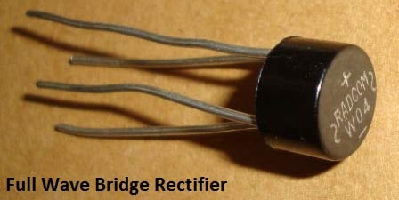
3. Filtration
The output after the Rectification is not a proper DC, it is oscillation output and has a very high ripple factor. We don’t need that pulsating output, for this we use Capacitor. Capacitor charge till the waveform goes to its peak and discharge into Load circuit when waveform goes low. So when output is going low, capacitor maintains the proper voltage supply into the Load circuit, hence creating the DC. Now how the value of this filter capacitor should be calculated. Here is the formulae:
C = I * t / V
C= capacitance to be calculated
I= Max output current (let’s say 500mA)
t= 10ms,
We will get wave of 100Hz frequency after converting 50Hz AC into DC, through full wave bridge rectifier. As the negative part of the pulse is converted into positive, one pulse will be counted two. So the Time period will be 1/100= .01 Second= 10ms
V = Peak voltage – voltage given to voltage regulator IC (+2 more than rated means 5+2=7)
9-0-9 is the RMS value of transforms so peak voltage is Vrms * 1.414= 9* 1.414= 12.73v
Now 1.4v will be dropped on 2 diodes (0.7 per diode) as 2 will be forward biased for half wave.
So 12.73 – 1.4 = 11.33v
When capacitor discharges into load circuit, it must provide 7v to 7805 IC to work so finally V is:
V = 11.33 – 7= 4.33v
So now C = I * t / V
C = 500mA * 10ms / 4.33 = .5 * .01 / 4.33 = 1154uF ~ 1000uF
4. Voltage Regulation
A voltage regulator IC 7805 is used to provide a regulated 5v DC. Input voltage should be 2volts more than the rated output voltage for proper working of IC, means at least 7v is needed, although it can operate in input voltage range of 7-20V. Voltage regulators have all the circuitry inside it to provide a proper regulated DC. Capacitor of 0.01uF should be connected to the output of the 7805 to eliminate the noise, produced by transient changes in voltage.
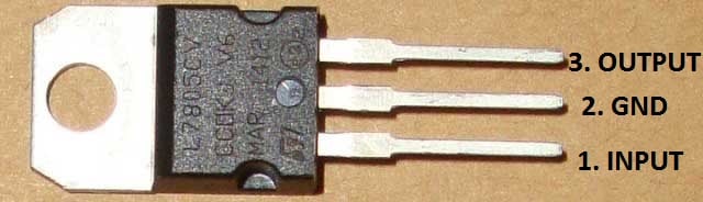
Wireless Power Transfer
Wireless Power Transfer System
One of the major problems in power system is the losses occurring during the transmission of electrical power. The loss of percentage during the transmission is approximated as 26%. The main cause for power loss during transmission is the resistance of wires used in the grid. According to WRI (world resource institute), the electricity grid of India has the highest percentage (27-40%) of power transmission losses in the world. For this reason, Telsa has proposed methods of electricity transmission using an electromagnetic induction method.
The Serbian scientist “Nikola Telsa” was the first one to research and propose the concept of wireless power transfer in the year 1899, since then many scientists have been working to make his vision a reality. In the same year he has continued research on wireless power transmission in Colorado Springs and writes, the inferiority of the induction method would come into view immense as compared with the distributed charge of ground and air method. In the year 1961, William C. Brown publishes an article exploring possibilities of microwave power transmission. In the year 2009, Sony shows a wireless electrodynamics induction powered TV set.
What is Wireless Power Transfer?
Wireless Power Transfer

Wireless power can be defined as the transmission of electrical energy from a power source to an electrical load without connecting wires. It is reliable, efficient, fast, low maintenance cost, and it can be used for short range or long range. The basic working principle of wireless power transfer is, two objects having similar resonant frequency and in magnetic resonance at powerfully coupled rule tends to exchange the energy, while dissipating relatively little energy to the extraneous off-resonant objects.
Moreover, this method can be involved in a variety of applications, like to charge mobile phones, laptops wirelessly. And also this kind of charging gives a far lower risk of electrical shock as it would be galvanically isolated. This is an emerging technology, and further, the distance of power transfer can be improved as the study across the world is still going on.
Hardware Requirements of Wireless Power Transfer
The hardware requirements of wireless power transfer include HF-Transformer, HF-diodes, rectifier, basic Transistors, Two air filled inductor coils, Voltage regulator and BLDC fan.
Wireless Power Transfer Block Diagram
HF-Transformer
HF-Transformer
High frequency (HF) transformers transfer electric power and the physical size are reliant on the power to be transformed as well as the operating frequency. The emf equation of universal transformer indicates that at a higher frequency, the core flux density will be lower for a given voltage. This implies that a core can have a smaller cross-sectional area.
power to be transformed as well as the operating frequency. The emf equation of universal transformer indicates that at a higher frequency, the core flux density will be lower for a given voltage. This implies that a core can have a smaller cross-sectional area.Voltage Regulator
A voltage regulator is an electrical regulator, designed to maintain a constant level voltage automatically.
Voltage Regulator
- There are three terminals positive voltage regulators are available in many packages and also with several o/p voltages, making them useful in a wide range of applications. Output current up to 1A and o/p voltage is 12.
- Thermal overload and short circuit protection
- Output transistor safe operating area protection
Coil
Coil
- An electromagnetic coil is formed when a conductor is wound around a core
- Primarily used to transfer energy from one electrical circuit to another by magnetic coupling
- Common types of electrical coils are Tesla, Barker, Choke, Maxwell coil, etc.
IN4007 Diode
1N4148 Diode
- This diode is used as full wave bridge rectifier circuit in this project
- Maximum reverse bias voltage capacity of 50V and max forward current capacity of 1Amp.
Project Working
The main concept of this project is to design a device for the concept of wireless power transfer to eliminate the use conventional copper cables and also current carrying wires.
This project is built upon using a circuit which converts AC 230V 50Hz to AC 12V, High frequency (HF). The output is fed to a tuned coil shaping as main of an air core transformer. The minor coil develops a voltage of HF 12volt.
Wireless Power Transfer Project Kit
Thus the power transfer can be done by the primary to the secondary that is divided with 3cm distance. So the transfer could be seen as the primary transmits and the secondary receives the power to run a load.
In addition, this method can be used in several applications, like to charge gadgets like mobile phone, laptop battery, iPod, propeller clock wirelessly. And also this type of charging offers a far lower risk of electrical shock as it would be galvanically isolated.
This is an Emerging Technology, and in future, the distance of power transfer can be improved as the study across the world is still going on.
Wireless Power Transfer Advantages
The advantages of WPT include the following
- Simple design
- Lower frequency operation
- Low cost
- Practical for short distance
Wireless Power Transfer Disadvantages
The disadvantages of WPT include the following
- High power loss
- Non-directionality
- Inefficient for longer distances
Wireless Power Transfer Applications
The applications of WPT include the following
- Consumer electronics
- Transport
- Heating and ventilation
- Industrial engineering
- Model engineering


+++++++++++++++++++++++++++++++++++++++++++++++++++++++++++++
e- Sensor in Hand Phone Smart Phone to be going e- Super Block Function

++++++++++++++++++++++++++++++++++++++++++++++++++++++++++++++
Tidak ada komentar:
Posting Komentar