
Plastic Materials: How to Make Plastic?
Plastics have been a supporting part of the activity of modern life for decades.
From household appliances to auto parts, plastics have provided affordable yet powerful materials for various appliances
 Pellet or plastic ore ready for further processing (injection molding, extrusion
salah satu penghasil biji plastik untuk jenis Polypropylene atau PP dan High Density PolyEthylene atau HDPE.


How to make Plastic


Intro


Intro: How to make Plastic
I have always searched for a quick and simple way to make plastic. I have tried many but the one in this instructable the best I have found. ...
1

Step 1: Materials
acetoneAcetone is commonly used as a paint thiner and can be found at your local hardware shop or at amazon.com.glass containerThis can be an empty pot of jam ...
2

Step 2: Prepare the Acetone
Open the canister of acetone and pour some acetone into the glass container. You don't need much, 1 centimeter should be enough for a little batch of plastic. ...
3

Step 3: Melt the Styrofoam
Start by breaking your block or blocks of Styrofoam in pieces that fit into your glass container. Then take the pieces and push them into the acetone. Continue ...
4

Step 4: Other Usefull Info
If you do not use the plastic immediately cover the container in which you put the plastic. If your plastic becomes to hard to work with dip it ...
5

Step 5: Safety
Acetone is a very dangerous chemical, read the safety instructions before using it. You should never drink or inhale it. Also, do not do this project near any ...
6

Step 6: The Science Behind It
Polystyrene is a polymer made from the monomer styrene, a liquid hydrocarbon that is commercially manufactured from petroleum by the chemical industry.The chemical makeup of polystyrene is a ...
I have always searched for a quick and simple way to make plastic. I have tried many but the one in this instructable the best I have found. It uses materials that you probably already have in your house,
it is fun to do and can be completed within minutes. I hope you will enjoy doing this instructable and will be able to learn something at the same time.
it is fun to do and can be completed within minutes. I hope you will enjoy doing this instructable and will be able to learn something at the same time.
Step 1: Materials

acetone
Acetone is commonly used as a paint thiner and can be found at your local hardware shop or at amazon.com.
glass container
This can be an empty pot of jam or a beaker.
expanded polystyrene (styrofoam)
You can buy styrofoam cups or use any other piece of styrofoam you have.
Acetone is commonly used as a paint thiner and can be found at your local hardware shop or at amazon.com.
glass container
This can be an empty pot of jam or a beaker.
expanded polystyrene (styrofoam)
You can buy styrofoam cups or use any other piece of styrofoam you have.
Step 2: Prepare the Acetone


1 cm of acetone
Open the canister of acetone and pour some acetone into the glass container. You don't need much, 1 centimeter should be enough for a little batch of plastic. If theres not enough you can always add some more later.
Step 3: Melt the Styrofoam


Start by breaking your block or blocks of Styrofoam in pieces that fit into your glass container. Then take the pieces and push them into the acetone. Continue pushing Styrofoam into the acetone until the blocks you put in don't melt anymore.
Then wait one to five minutes for some of the acetone to evaporate. Wait one minute if you want it to mold the plastic and five if you want to shape it. The more you let the acetone evaporate the more solid it will be. You might even want to mold it while its still "liquid".


If you do not use the plastic immediately cover the container in which you put the plastic.
If your plastic becomes to hard to work with dip it in some acetone to make it soft again.
The plastic fully cures in about 12 hours.
Step 5: Safety

Here's an extract of the MSDS safety sheet: "May be harmful by inhalation, ingestion or skin absorption. Irritant. Liquid may cause permanent eye damage (corneal clouding). Contact with skin may cause defatting, leading to irritation. Long-term exposure may cause liver damage." Wearing gloves is a good idea, but you'll have to use butyl rubber gloves or some other kind of acetone resistant glove
costs and liabilities.
Step 6: The Science Behind It
Genetic engineering plants as bioreactors: Biotechnologists introduce bacterial genes into plants. These genes code for the enzymes to make bacterial plastics. The plants are grown and harvested, and the plastics are extracted from the plant material.
In 1997, Cargille Dow made a clear plastic (polylactide) from corn. The polylactide fibers were woven into sports apparel, upholstery fabrics and bioplastic wraps.
Bioplastics have the advantage of being produced from renewable resources (bacteria, plants) rather than nonrenewable resources (oil, natural gas). Furthermore, bioplastics are biodegradable -- they can break down in the environment (see How Landfills Work). Bioplastics is a potentially important industry. With current technology, bioplastics might be more expensive to produce, but biotechnology is rapidly advancing and production may become more economical in the future.
Once collected, plastics go through the following steps
The discovery of plastics revolutionized our society by introducing a huge variety of lightweight, strong, flexible products with many uses. Although plastics do pose disposal problems, recycling is always a possibility. Furthermore, new research into biopolymers may produce new bioplastic products from renewable resources that are biodegradable and easier on our environment.
 As we mentioned earlier, there are other polymers besides plastics. Naturally occurring polymers, such as starches, cellulose, soy protein, vegetable oil, triglycerides and bacterial polyesters, can be extracted from crops and bacteria. Furthermore, plants and microorganisms can produce substances like lactic acid, which can be polymerized into bioplastics (polylactic acid, for example). There are two strategies for producing bioplastics.
Fermentation: Bacteria or other microorganisms mass-produce the biopolymers in bioreactors (fermentation tanks). The biopolymers (lactic acid, polyesters) are extracted from the bioreactors and chemically processed into plastics.

X . IIII
Magnet


A magnet (from Greek μαγνήτις λίθος magnḗtis líthos, "Magnesian stone") is a material or object that produces a magnetic field. This magnetic field is invisible but is responsible for the most notable property of a magnet: a force that pulls on other ferromagnetic materials, such as iron, and attracts or repels other magnets.
A permanent magnet is an object made from a material that is magnetized and creates its own persistent magnetic field. An everyday example is a refrigerator magnet used to hold notes on a refrigerator door. Materials that can be magnetized, which are also the ones that are strongly attracted to a magnet, are called ferromagnetic (or ferrimagnetic). These include iron, nickel, cobalt, some alloys of rare-earth metals, and some naturally occurring minerals such as lodestone. Although ferromagnetic (and ferrimagnetic) materials are the only ones attracted to a magnet strongly enough to be commonly considered magnetic, all other substances respond weakly to a magnetic field, by one of several other types of magnetism.
Ferromagnetic materials can be divided into magnetically "soft" materials like annealed iron, which can be magnetized but do not tend to stay magnetized, and magnetically "hard" materials, which do. Permanent magnets are made from "hard" ferromagnetic materials such as alnico and ferrite that are subjected to special processing in a strong magnetic field during manufacture to align their internal microcrystalline structure, making them very hard to demagnetize. To demagnetize a saturated magnet, a certain magnetic field must be applied, and this threshold depends on coercivity of the respective material. "Hard" materials have high coercivity , whereas "soft" materials have low coercivity.
An electromagnet is made from a coil of wire that acts as a magnet when an electric current passes through it but stops being a magnet when the current stops. Often, the coil is wrapped around a core of "soft" ferromagnetic material such as steel, which greatly enhances the magnetic field produced by the coil.
The overall strength of a magnet is measured by its magnetic moment or, alternatively, the total magnetic flux it produces. The local strength of magnetism in a material is measured by its magnetization.
 A "horseshoe magnet" made of alnico, an iron alloy. The magnet, made in the shape of a horseshoe, has the two magnetic poles close together. This shape creates a strong magnetic field between the poles, allowing the magnet to pick up a heavy piece of iron .

Magnetic field lines of a solenoid electromagnet, which are similar to a bar magnet as illustrated below with the iron filings
By the 12th to 13th centuries AD, magnetic compasses were used in navigation in China, Europe, the Arabian Peninsula and elsewhere.
A magnet both produces its own magnetic field and responds to magnetic fields. The strength of the magnetic field it produces is at any given point proportional to the magnitude of its magnetic moment. In addition, when the magnet is put into an external magnetic field, produced by a different source, it is subject to a torque tending to orient the magnetic moment parallel to the field. The amount of this torque is proportional both to the magnetic moment and the external field. A magnet may also be subject to a force driving it in one direction or another, according to the positions and orientations of the magnet and source. If the field is uniform in space, the magnet is subject to no net force, although it is subject to a torque.
A wire in the shape of a circle with area A and carrying current I is a magnet, with a magnetic moment of magnitude equal to IA.
Although for many purposes it is convenient to think of a magnet as having distinct north and south magnetic poles, the concept of poles should not be taken literally: it is merely a way of referring to the two different ends of a magnet. The magnet does not have distinct north or south particles on opposing sides. If a bar magnet is broken into two pieces, in an attempt to separate the north and south poles, the result will be two bar magnets, each of which has both a north and south pole. However, a version of the magnetic-pole approach is used by professional magneticians to design permanent magnets.
In this approach, the divergence of the magnetization ∇·M inside a magnet and the surface normal component M·n are treated as a distribution of magnetic monopoles. This is a mathematical convenience and does not imply that there are actually monopoles in the magnet. If the magnetic-pole distribution is known, then the pole model gives the magnetic field H. Outside the magnet, the field B is proportional to H, while inside the magnetization must be added to H. An extension of this method that allows for internal magnetic charges is used in theories of ferromagnetism.
Another model is the Ampère model, where all magnetization is due to the effect of microscopic, or atomic, circular bound currents, also called Ampèrian currents, throughout the material. For a uniformly magnetized cylindrical bar magnet, the net effect of the microscopic bound currents is to make the magnet behave as if there is a macroscopic sheet of electric current flowing around the surface, with local flow direction normal to the cylinder axis.[12] Microscopic currents in atoms inside the material are generally canceled by currents in neighboring atoms, so only the surface makes a net contribution; shaving off the outer layer of a magnet will not destroy its magnetic field, but will leave a new surface of uncancelled currents from the circular currents throughout the material. The right-hand rule tells which direction the current flows.
The overall magnetic behavior of a material can vary widely, depending on the structure of the material, particularly on its electron configuration. Several forms of magnetic behavior have been observed in different materials, including:


If a ferromagnetic foreign body is present in human tissue, an external magnetic field interacting with it can pose a serious safety risk.
A different type of indirect magnetic health risk exists involving pacemakers. If a pacemaker has been embedded in a patient's chest (usually for the purpose of monitoring and regulating the heart for steady electrically induced beats), care should be taken to keep it away from magnetic fields. It is for this reason that a patient with the device installed cannot be tested with the use of a magnetic resonance imaging device.
Children sometimes swallow small magnets from toys, and this can be hazardous if two or more magnets are swallowed, as the magnets can pinch or puncture internal tissues; one death has been reported.
Magnetic imaging devices (e.g. MRIs) generate enormous magnetic fields, and therefore rooms intended to hold them exclude ferrous metals. Bringing objects made of ferrous metals (such as oxygen canisters) into such a room creates a severe safety risk, as those objects may be powerfully thrown about by the intense magnetic fields.

Alnico magnets are made by casting or sintering a combination of aluminium, nickel and cobalt with iron and small amounts of other elements added to enhance the properties of the magnet. Sintering offers superior mechanical characteristics, whereas casting delivers higher magnetic fields and allows for the design of intricate shapes. Alnico magnets resist corrosion and have physical properties more forgiving than ferrite, but not quite as desirable as a metal. Trade names for alloys in this family include: Alni, Alcomax, Hycomax, Columax, and Ticonal.
Injection-molded magnets are a composite of various types of resin and magnetic powders, allowing parts of complex shapes to be manufactured by injection molding. The physical and magnetic properties of the product depend on the raw materials, but are generally lower in magnetic strength and resemble plastics in their physical properties.
Flexible magnets are composed of a high-coercivity ferromagnetic compound (usually ferric oxide) mixed with a plastic binder. This is extruded as a sheet and passed over a line of powerful cylindrical permanent magnets. These magnets are arranged in a stack with alternating magnetic poles facing up (N, S, N, S...) on a rotating shaft. This impresses the plastic sheet with the magnetic poles in an alternating line format. No electromagnetism is used to generate the magnets. The pole-to-pole distance is on the order of 5 mm, but varies with manufacturer. These magnets are lower in magnetic strength but can be very flexible, depending on the binder used.
 Rare earth (lanthanoid) elements have a partially occupied f electron shell (which can accommodate up to 14 electrons). The spin of these electrons can be aligned, resulting in very strong magnetic fields, and therefore, these elements are used in compact high-strength magnets where their higher price is not a concern. The most common types of rare-earth magnets are samarium-cobalt and neodymium-iron-boron (NIB) magnets.
Additionally, some magnets are brittle and can fracture at high temperatures.
The maximum usable temperature is highest for alnico magnets at over 540 °C (1,000 °F), around 300 °C (570 °F) for ferrite and SmCo, about 140 °C (280 °F) for NIB and lower for flexible ceramics, but the exact numbers depend on the grade of material.
If the coil of wire is wrapped around a material with no special magnetic properties (e.g., cardboard), it will tend to generate a very weak field. However, if it is wrapped around a soft ferromagnetic material, such as an iron nail, then the net field produced can result in a several hundred- to thousandfold increase of field strength.
Uses for electromagnets include particle accelerators, electric motors, junkyard cranes, and magnetic resonance imaging machines. Some applications involve configurations more than a simple magnetic dipole; for example, quadrupole and sextupole magnets are used to focus particle beams.
In all units, it is convenient to employ two types of magnetic field, B and H, as well as the magnetization M, defined as the magnetic moment per unit volume.
Caution: in part because there are not enough Roman and Greek symbols, there is no commonly agreed-upon symbol for magnetic pole strength and magnetic moment. The symbol m has been used for both pole strength (unit A•m, where here the upright m is for meter) and for magnetic moment (unit A•m2). The symbol μ has been used in some texts for magnetic permeability and in other texts for magnetic moment. We will use μ for magnetic permeability and m for magnetic moment. For pole strength, we will employ qm. For a bar magnet of cross-section A with uniform magnetization M along its axis, the pole strength is given by qm = MA, so that M can be thought of as a pole strength per unit area.
Closer to the magnet, the magnetic field becomes more complicated and more dependent on the detailed shape and magnetization of the magnet. Formally, the field can be expressed as a multipole expansion: A dipole field, plus a quadrupole field, plus an octupole field, etc.
At close range, many different fields are possible. For example, for a long, skinny bar magnet with its north pole at one end and south pole at the other, the magnetic field near either end falls off inversely with the square of the distance from that pole.
When , the point dipole approximation is obtained,
X . IIIII
Plastic magnet
A plastic magnet is a non-metallic magnet made from an organic polymer .
plastic magnet is a conductive polymer that is stable in air. When combined with the free radical-forming TCNQ as an acceptor molecule, it can mimic the mechanism of metallic magnets. The magnetic properties arise from the fully pi-conjugated nitrogen-containing backbone combined with molecular charge transfer side groups. These properties cause the molecule to have a high density of localized spins that can give rise to coupling of their magnetic fields. When this polymer magnet is synthesized, the polymer chains need 3 months to line up before displaying any notable magnetism.
Plastic magnets could have uses in computer hardware, for example as disc drives and in medical devices such as pacemakers and cochlear implants where the organic material is more likely to be biocompatible than its metallic counterpart.
In February 2002, researchers from Ohio State University & University of Utah developed the world's first light-tunable plastic magnet.[2] The plastic material became 1.5 times more magnetic when blue light shines on it. Green laser light reversed the effect somewhat, by decreasing the material's magnetism to 60 percent of its normal level. The plastic magnet was made from a polymer made of tetracyanoethylene (TCNE) combined with manganese (Mn) ions -- atoms of the metal manganese with electrons removed. The magnet functioned up to a temperature of 75 K (about -200ºC, or -325ºF).
Magnetic Permeability: Why Are Some Materials Attracted By A Magnet And Others Are Not?
Two magnets attract to each other because their fields interact. Usually materials that are not magnets do not have a net external field, and obviously, they do not attract to things; however, some metal alloys can have a net field created by applying an external field. This induced field is only present when the external drive field is applied.
A permanent magnet is “attracted” to a ferrous work-piece because magnetism is “induced” in the work-piece. The magnetism is induced by the magnetic field emanating from the permanent magnet. (A work-piece is what the magnet or magnetic field is acting on. This could be the steel door skin of a refrigerator, a nail, a metal plate used in a magnetic latch, etc.) A magnet is not attracted to a piece of wood because no internal field in induced in the wood. With no induced internal field in the wood, there is no field interaction and no attraction.
So, a magnetic field can be induced in a piece of steel. As stated above, an external magnetic field is needed to do this. That is why two pieces of steel do not attract to each other. They do not induce fields in each other. No field, no interaction, no attraction.
The degree of the induced magnetism is related to the ferrous material’s magnetic permeability, and it is expressed as a unit-less value designated by the Greek letter, mu (μ). The higher the material’s permeability, the greater the magnetic induction and the resulting force of attraction. As shown below, a material’s permeability is not constant and does have a limit.
Materials that are not attracted to a magnet like air, wood, plastic, brass, etc., have a permeability of, essentially, 1. There is no magnetism induced in them by an external magnetic field, and therefore, they are not attracted by a magnet. Ferrous, Nickel, and Cobalt alloys have a high permeability (μ), and thereby, magnetic fields can be induced in them when exposed to an external magnetic field.
WARNING for Engineers! First order equation: B = μH
Induced Magnetism in an Alloy (B) = Alloy’s Permeability (μ) X External Applied Drive Field (H)
 In the CGS unit system:
B is in (Gauss) Permeability (unit-less) External Field strength (Oersted)
Mild Steel Example:
Induced (Internal Field) = ~ 15,000 Gauss = (30) x 500 Oersted
The 15,000 Gauss field induced in the mild steel interacts with the applied magnetic field, and there is attraction.
In Figure 1, it can be observed how the Flux lines are denser in the steel, showing the induced field, as well as how the Flux Lines “bend” in the steel alloy. The steel’s magnetic properties bias or interact with the magnet’s magnetic flux lines (Field).
 Wood Example:
Induced (Internal Field) = 500 Gauss (1) x 500 Oersted
The only field in the wood is from the externally applied magnetic field and no new field is induced to interact with the applied field. No Attraction!
In Figure 2, it can be observed how the Flux Lines are not biased by the wood at all, and there is no induced field. The Flux Lines do not “bend” in the wood and pass through as if it is not there. There is no Field to Field interaction and no attraction.
The permeability of a material is not constant, and for a given temperature, it changes based on the intensity of the applied external magnetic field (H). The relative aspect of permeability is more apparent when illustrated with a graph depicting a material’s permeability relative to the applied external field. (Refer to Figure 3)
 Oftentimes, technical books will list a material’s magnetic permeability as a constant, but this is far from accurate and is very misleading. For instance, Image 3 is a plot for mild Steel C-1018, and it illustrates the Induced Magnetism (G) for various applied Field Strength levels (H). It also depicts the corresponding magnetic permeability at each applied field strength level. The permeability for C-1018 may be advertised as 100 (in the CGS unit system), but this is the peak value, and it is less than 20 over most of the curve.
A material’s permeability is important, because it allows one to anticipate the performance of a magnet when used in a design. For instance, a customer may want to pick up automobile exhaust tubing with a magnetic end effector on a robot-arm. When the tube is made from an aluminized mild steel alloy the magnet handling device may work just fine; however, when the tube is 410 SS, the tube may be dropped. The force of attraction between the handling magnet and the tube is greater with the aluminized mild steel than the 410 SS because the mild steel has a higher permeability than the 410 SS.
Key Points:

Magnetics Deeper Entry into the Aerospace Industry

Receiving the AS9100C certification gave us the opportunity to demonstrate our knowledge and expertise in quality management. This certification reveals that we understand the best practices across the aerospace industry – one of the most rigorous and quality-driven industries in manufacturing. By integrating these practices throughout our own organization, we are able to further improve our current products and services.
Apple Watch Sport includes a plastic magnetic charger, not metal like the more expensive models

\
As users unbox their new Apple Watch units today, customers who bought the Sport version are receiving a bit of a surprise. The inductive charging cable bundled with Apple Watch Sport is actually made of plastic rather than the nice metal finishes of the more expensive stainless steel and gold watches.
The material is very similar to other Apple accessories which have white gloss exteriors. It’s unclear why the Sport does not get the fancier cable: it may be simply for cost-saving purposes to maximize Apple’s bottom line or it may be a design choice to better match the materials of the Watch itself.
The Sport charger was actually spotted in an Apple environment video although at the time it was unidentifiable. Apple’s public messaging did not make this distinction clear between the variants of Apple Watch, so some customers unwrapping their Apple Watch Sport purchases may be disappointed by this revelation.


X . IIIIII
HANDHELD SEISMOMETER


In 1997, Cargille Dow made a clear plastic (polylactide) from corn. The polylactide fibers were woven into sports apparel, upholstery fabrics and bioplastic wraps.
Bioplastics have the advantage of being produced from renewable resources (bacteria, plants) rather than nonrenewable resources (oil, natural gas). Furthermore, bioplastics are biodegradable -- they can break down in the environment (see How Landfills Work). Bioplastics is a potentially important industry. With current technology, bioplastics might be more expensive to produce, but biotechnology is rapidly advancing and production may become more economical in the future.
Recycling Plastics
Oil-based plastics don't degrade, but many types (including PP, LDPE, HDPE, PET, and PVC) can be recycled. Each type has a code and identifying number, but some plastics aren't as economically feasible to recycle. So it's important to check with your recycler or municipality about which types of plastics will be accepted.Once collected, plastics go through the following steps
- Inspection to weed out contaminants and inappropriate types of plastic
- Shredding and washing
- Separation based on density
- Drying
- Melting
- Draining through fine screens to remove more contaminants
- Cooling and shredding into pellets
- Selling back to plastic companies
Biopolymers and Recycling

Pioneer electronics researcher Tasuo Hosoda displays a prototype model of a Blu-ray disc made of corn starch polymer. On the right are corn starch polymer pellets.
Fermentation: Bacteria or other microorganisms mass-produce the biopolymers in bioreactors (fermentation tanks). The biopolymers (lactic acid, polyesters) are extracted from the bioreactors and chemically processed into plastics.
X . IIII
Magnet
A magnet (from Greek μαγνήτις λίθος magnḗtis líthos, "Magnesian stone") is a material or object that produces a magnetic field. This magnetic field is invisible but is responsible for the most notable property of a magnet: a force that pulls on other ferromagnetic materials, such as iron, and attracts or repels other magnets.
A permanent magnet is an object made from a material that is magnetized and creates its own persistent magnetic field. An everyday example is a refrigerator magnet used to hold notes on a refrigerator door. Materials that can be magnetized, which are also the ones that are strongly attracted to a magnet, are called ferromagnetic (or ferrimagnetic). These include iron, nickel, cobalt, some alloys of rare-earth metals, and some naturally occurring minerals such as lodestone. Although ferromagnetic (and ferrimagnetic) materials are the only ones attracted to a magnet strongly enough to be commonly considered magnetic, all other substances respond weakly to a magnetic field, by one of several other types of magnetism.
Ferromagnetic materials can be divided into magnetically "soft" materials like annealed iron, which can be magnetized but do not tend to stay magnetized, and magnetically "hard" materials, which do. Permanent magnets are made from "hard" ferromagnetic materials such as alnico and ferrite that are subjected to special processing in a strong magnetic field during manufacture to align their internal microcrystalline structure, making them very hard to demagnetize. To demagnetize a saturated magnet, a certain magnetic field must be applied, and this threshold depends on coercivity of the respective material. "Hard" materials have high coercivity , whereas "soft" materials have low coercivity.
An electromagnet is made from a coil of wire that acts as a magnet when an electric current passes through it but stops being a magnet when the current stops. Often, the coil is wrapped around a core of "soft" ferromagnetic material such as steel, which greatly enhances the magnetic field produced by the coil.
The overall strength of a magnet is measured by its magnetic moment or, alternatively, the total magnetic flux it produces. The local strength of magnetism in a material is measured by its magnetization.
 A "horseshoe magnet" made of alnico, an iron alloy. The magnet, made in the shape of a horseshoe, has the two magnetic poles close together. This shape creates a strong magnetic field between the poles, allowing the magnet to pick up a heavy piece of iron .
Magnetic field lines of a solenoid electromagnet, which are similar to a bar magnet as illustrated below with the iron filings
Discovery and development
Ancient people learned about magnetism from lodestones, which are naturally magnetized pieces of iron ore. The word magnet was adopted in Middle English from Latin magnetum "lodestone", ultimately from Greek μαγνῆτις [λίθος] (magnētis [lithos]) meaning "[stone] from Magnesia", a part of ancient Greece where lodestones were found. Lodestones, suspended so they could turn, were the first magnetic compasses. The earliest known surviving descriptions of magnets and their properties are from Greece, India, and China around 2500 years ago. The properties of lodestones and their affinity for iron were written of by Pliny the Elder in his encyclopedia Naturalis Historia.By the 12th to 13th centuries AD, magnetic compasses were used in navigation in China, Europe, the Arabian Peninsula and elsewhere.
Physics
Magnetic field
The magnetic flux density (also called magnetic B field or just magnetic field, usually denoted B) is a vector field. The magnetic B field vector at a given point in space is specified by two properties:
- Its direction, which is along the orientation of a compass needle.
- Its magnitude (also called strength), which is proportional to how strongly the compass needle orients along that direction.
Magnetic moment
A magnet's magnetic moment (also called magnetic dipole moment and usually denoted μ) is a vector that characterizes the magnet's overall magnetic properties. For a bar magnet, the direction of the magnetic moment points from the magnet's south pole to its north pole, and the magnitude relates to how strong and how far apart these poles are. In SI units, the magnetic moment is specified in terms of A·m2 (amperes times meters squared).A magnet both produces its own magnetic field and responds to magnetic fields. The strength of the magnetic field it produces is at any given point proportional to the magnitude of its magnetic moment. In addition, when the magnet is put into an external magnetic field, produced by a different source, it is subject to a torque tending to orient the magnetic moment parallel to the field. The amount of this torque is proportional both to the magnetic moment and the external field. A magnet may also be subject to a force driving it in one direction or another, according to the positions and orientations of the magnet and source. If the field is uniform in space, the magnet is subject to no net force, although it is subject to a torque.
A wire in the shape of a circle with area A and carrying current I is a magnet, with a magnetic moment of magnitude equal to IA.
Magnetization
The magnetization of a magnetized material is the local value of its magnetic moment per unit volume, usually denoted M, with units A/m. It is a vector field, rather than just a vector (like the magnetic moment), because different areas in a magnet can be magnetized with different directions and strengths (for example, because of domains, see below). A good bar magnet may have a magnetic moment of magnitude 0.1 A•m2 and a volume of 1 cm3, or 1×10⁻⁶ m3, and therefore an average magnetization magnitude is 100,000 A/m. Iron can have a magnetization of around a million amperes per meter. Such a large value explains why iron magnets are so effective at producing magnetic fields.Modelling magnets
Two different models exist for magnets: magnetic poles and atomic currents.
Although for many purposes it is convenient to think of a magnet as having distinct north and south magnetic poles, the concept of poles should not be taken literally: it is merely a way of referring to the two different ends of a magnet. The magnet does not have distinct north or south particles on opposing sides. If a bar magnet is broken into two pieces, in an attempt to separate the north and south poles, the result will be two bar magnets, each of which has both a north and south pole. However, a version of the magnetic-pole approach is used by professional magneticians to design permanent magnets.
In this approach, the divergence of the magnetization ∇·M inside a magnet and the surface normal component M·n are treated as a distribution of magnetic monopoles. This is a mathematical convenience and does not imply that there are actually monopoles in the magnet. If the magnetic-pole distribution is known, then the pole model gives the magnetic field H. Outside the magnet, the field B is proportional to H, while inside the magnetization must be added to H. An extension of this method that allows for internal magnetic charges is used in theories of ferromagnetism.
Another model is the Ampère model, where all magnetization is due to the effect of microscopic, or atomic, circular bound currents, also called Ampèrian currents, throughout the material. For a uniformly magnetized cylindrical bar magnet, the net effect of the microscopic bound currents is to make the magnet behave as if there is a macroscopic sheet of electric current flowing around the surface, with local flow direction normal to the cylinder axis.[12] Microscopic currents in atoms inside the material are generally canceled by currents in neighboring atoms, so only the surface makes a net contribution; shaving off the outer layer of a magnet will not destroy its magnetic field, but will leave a new surface of uncancelled currents from the circular currents throughout the material. The right-hand rule tells which direction the current flows.
Pole naming conventions
The north pole of a magnet is defined as the pole that, when the magnet is freely suspended, points towards the Earth's North Magnetic Pole in the Arctic ( the magnetic and geographic poles do not coincide, see magnetic declination). Since opposite poles (north and south) attract, the North Magnetic Pole is actually the south pole of the Earth's magnetic field. As a practical matter, to tell which pole of a magnet is north and which is south, it is not necessary to use the Earth's magnetic field at all. For example, one method would be to compare it to an electromagnet, whose poles can be identified by the right-hand rule. The magnetic field lines of a magnet are considered by convention to emerge from the magnet's north pole and reenter at the south pole.Magnetic materials
The term magnet is typically reserved for objects that produce their own persistent magnetic field even in the absence of an applied magnetic field. Only certain classes of materials can do this. Most materials, however, produce a magnetic field in response to an applied magnetic field – a phenomenon known as magnetism. There are several types of magnetism, and all materials exhibit at least one of them.The overall magnetic behavior of a material can vary widely, depending on the structure of the material, particularly on its electron configuration. Several forms of magnetic behavior have been observed in different materials, including:
- Ferromagnetic and ferrimagnetic materials are the ones normally thought of as magnetic; they are attracted to a magnet strongly enough that the attraction can be felt. These materials are the only ones that can retain magnetization and become magnets; a common example is a traditional refrigerator magnet. Ferrimagnetic materials, which include ferrites and the oldest magnetic materials magnetite and lodestone, are similar to but weaker than ferromagnetics. The difference between ferro- and ferrimagnetic materials is related to their microscopic structure, as explained in Magnetism.
- Paramagnetic substances, such as platinum, aluminum, and oxygen, are weakly attracted to either pole of a magnet. This attraction is hundreds of thousands of times weaker than that of ferromagnetic materials, so it can only be detected by using sensitive instruments or using extremely strong magnets. Magnetic ferrofluids, although they are made of tiny ferromagnetic particles suspended in liquid, are sometimes considered paramagnetic since they cannot be magnetized.
- Diamagnetic means repelled by both poles. Compared to paramagnetic and ferromagnetic substances, diamagnetic substances, such as carbon, copper, water, and plastic, are even more weakly repelled by a magnet. The permeability of diamagnetic materials is less than the permeability of a vacuum. All substances not possessing one of the other types of magnetism are diamagnetic; this includes most substances. Although force on a diamagnetic object from an ordinary magnet is far too weak to be felt, using extremely strong superconducting magnets, diamagnetic objects such as pieces of lead and even mice can be levitated, so they float in mid-air. Superconductors repel magnetic fields from their interior and are strongly diamagnetic.
Common uses

Hard disk drives record data on a thin magnetic coating

- Magnetic recording media: VHS tapes contain a reel of magnetic tape. The information that makes up the video and sound is encoded on the magnetic coating on the tape. Common audio cassettes also rely on magnetic tape. Similarly, in computers, floppy disks and hard disks record data on a thin magnetic coating.
- Credit, debit, and automatic teller machine cards: All of these cards have a magnetic strip on one side. This strip encodes the information to contact an individual's financial institution and connect with their account(s).
- Older types of televisions (non flat screen) and older large computer monitors: TV and computer screens containing a cathode ray tube employ an electromagnet to guide electrons to the screen.[21] Plasma screens and LCDs use different technologies.
- Speakers and microphones: Most speakers employ a permanent magnet and a current-carrying coil to convert electric energy (the signal) into mechanical energy (movement that creates the sound). The coil is wrapped around a bobbin attached to the speaker cone and carries the signal as changing current that interacts with the field of the permanent magnet. The voice coil feels a magnetic force and in response, moves the cone and pressurizes the neighboring air, thus generating sound. Dynamic microphones employ the same concept, but in reverse. A microphone has a diaphragm or membrane attached to a coil of wire. The coil rests inside a specially shaped magnet. When sound vibrates the membrane, the coil is vibrated as well. As the coil moves through the magnetic field, a voltage is induced across the coil. This voltage drives a current in the wire that is characteristic of the original sound.
- Electric guitars use magnetic pickups to transduce the vibration of guitar strings into electric current that can then be amplified. This is different from the principle behind the speaker and dynamic microphone because the vibrations are sensed directly by the magnet, and a diaphragm is not employed. The Hammond organ used a similar principle, with rotating tonewheels instead of strings.
- Electric motors and generators: Some electric motors rely upon a combination of an electromagnet and a permanent magnet, and, much like loudspeakers, they convert electric energy into mechanical energy. A generator is the reverse: it converts mechanical energy into electric energy by moving a conductor through a magnetic field.
- Medicine: Hospitals use magnetic resonance imaging to spot problems in a patient's organs without invasive surgery.
- Chemistry: Chemists use nuclear magnetic resonance to characterize synthesized compounds.
- Chucks are used in the metalworking field to hold objects. Magnets are also used in other types of fastening devices, such as the magnetic base, the magnetic clamp and the refrigerator magnet.
- Compasses: A compass (or mariner's compass) is a magnetized pointer free to align itself with a magnetic field, most commonly Earth's magnetic field.
- Art: Vinyl magnet sheets may be attached to paintings, photographs, and other ornamental articles, allowing them to be attached to refrigerators and other metal surfaces. Objects and paint can be applied directly to the magnet surface to create collage pieces of art. Magnetic art is portable, inexpensive and easy to create. Vinyl magnetic art is not for the refrigerator anymore. Colorful metal magnetic boards, strips, doors, microwave ovens, dishwashers, cars, metal I beams, and any metal surface can be receptive of magnetic vinyl art. Being a relatively new media for art, the creative uses for this material is just beginning.
- Science projects: Many topic questions are based on magnets, including the repulsion of current-carrying wires, the effect of temperature, and motors involving magnets.[22]

Magnets have many uses in toys. M-tic uses magnetic rods connected to metal spheres for construction. Note the geodesic tetrahedron
- Toys: Given their ability to counteract the force of gravity at close range, magnets are often employed in children's toys, such as the Magnet Space Wheel and Levitron, to amusing effect.
- Refrigerator magnets are used to adorn kitchens, as a souvenir, or simply to hold a note or photo to the refrigerator door.
- Magnets can be used to make jewelry. Necklaces and bracelets can have a magnetic clasp, or may be constructed entirely from a linked series of magnets and ferrous beads.
- Magnets can pick up magnetic items (iron nails, staples, tacks, paper clips) that are either too small, too hard to reach, or too thin for fingers to hold. Some screwdrivers are magnetized for this purpose.
- Magnets can be used in scrap and salvage operations to separate magnetic metals (iron, cobalt, and nickel) from non-magnetic metals (aluminum, non-ferrous alloys, etc.). The same idea can be used in the so-called "magnet test", in which an auto body is inspected with a magnet to detect areas repaired using fiberglass or plastic putty.
- Magnets are found in process industries, food manufacturing especially, in order to remove metal foreign bodies from materials entering the process (raw materials) or to detect a possible contamination at the end of the process and prior to packaging. They constitute an important layer of protection for the process equipment and for the final consumer.
- Magnetic levitation transport, or maglev, is a form of transportation that suspends, guides and propels vehicles (especially trains) through electromagnetic force. Eliminating rolling resistance increases efficiency. The maximum recorded speed of a maglev train is 581 kilometers per hour (361 mph).
- Magnets may be used to serve as a fail-safe device for some cable connections. For example, the power cords of some laptops are magnetic to prevent accidental damage to the port when tripped over. The MagSafe power connection to the Apple MacBook is one such example.
Medical issues and safety
Because human tissues have a very low level of susceptibility to static magnetic fields, there is little mainstream scientific evidence showing a health effect associated with exposure to static fields. Dynamic magnetic fields may be a different issue, however; correlations between electromagnetic radiation and cancer rates have been postulated due to demographic correlations (see Electromagnetic radiation and health).If a ferromagnetic foreign body is present in human tissue, an external magnetic field interacting with it can pose a serious safety risk.
A different type of indirect magnetic health risk exists involving pacemakers. If a pacemaker has been embedded in a patient's chest (usually for the purpose of monitoring and regulating the heart for steady electrically induced beats), care should be taken to keep it away from magnetic fields. It is for this reason that a patient with the device installed cannot be tested with the use of a magnetic resonance imaging device.
Children sometimes swallow small magnets from toys, and this can be hazardous if two or more magnets are swallowed, as the magnets can pinch or puncture internal tissues; one death has been reported.
Magnetic imaging devices (e.g. MRIs) generate enormous magnetic fields, and therefore rooms intended to hold them exclude ferrous metals. Bringing objects made of ferrous metals (such as oxygen canisters) into such a room creates a severe safety risk, as those objects may be powerfully thrown about by the intense magnetic fields.
Magnetizing ferromagnets
Ferromagnetic materials can be magnetized in the following ways:- Heating the object above its Curie temperature, allowing it to cool in a magnetic field and hammering it as it cools. This is the most effective method and is similar to the industrial processes used to create permanent magnets.
- Placing the item in an external magnetic field will result in the item retaining some of the magnetism on removal. Vibration has been shown to increase the effect. Ferrous materials aligned with the Earth's magnetic field that are subject to vibration (e.g., frame of a conveyor) have been shown to acquire significant residual magnetism. Likewise, striking a steel nail held by fingers in a N-S direction with a hammer will temporarily magnetize the nail.
- Stroking: An existing magnet is moved from one end of the item to the other repeatedly in the same direction.
- Electric Current: Applying an electric current via a coil can get all of the domains to line up. Once all of the domains are lined up, increasing the current will not increase the strength of the magnetic field.
Demagnetizing ferromagnets
Magnetized ferromagnetic materials can be demagnetized (or degaussed) in the following ways:- Heating a magnet past its Curie temperature; the molecular motion destroys the alignment of the magnetic domains. This always removes all magnetization.
- Placing the magnet in an alternating magnetic field with intensity above the material's coercivity and then either slowly drawing the magnet out or slowly decreasing the magnetic field to zero. This is the principle used in commercial demagnetizers to demagnetize tools and erase credit cards and hard disks and degaussing coils used to demagnetize CRTs.
- Some demagnetization or reverse magnetization will occur if any part of the magnet is subjected to a reverse field above the magnetic material's coercivity.
- Demagnetisation progressively occurs if the magnet is subjected to cyclic fields sufficient to move the magnet away from the linear part on the second quadrant of the B-H curve of the magnetic material (the demagnetisation curve).
- Hammering or jarring: the mechanical disturbance tends to randomize the magnetic domains. This will leave some residual magnetization.
Types of permanent magnets

A stack of ferrite magnets
Magnetic metallic elements
Many materials have unpaired electron spins, and the majority of these materials are paramagnetic. When the spins interact with each other in such a way that the spins align spontaneously, the materials are called ferromagnetic (what is often loosely termed as magnetic). Because of the way their regular crystalline atomic structure causes their spins to interact, some metals are ferromagnetic when found in their natural states, as ores. These include iron ore (magnetite or lodestone), cobalt and nickel, as well as the rare earth metals gadolinium and dysprosium (when at a very low temperature). Such naturally occurring ferromagnets were used in the first experiments with magnetism. Technology has since expanded the availability of magnetic materials to include various man-made products, all based, however, on naturally magnetic elements.Composites
Ceramic, or ferrite, magnets are made of a sintered composite of powdered iron oxide and barium/strontium carbonate ceramic. Given the low cost of the materials and manufacturing methods, inexpensive magnets (or non-magnetized ferromagnetic cores, for use in electronic components such as radio antennas, for example) of various shapes can be easily mass-produced. The resulting magnets are non-corroding but brittle and must be treated like other ceramics.Alnico magnets are made by casting or sintering a combination of aluminium, nickel and cobalt with iron and small amounts of other elements added to enhance the properties of the magnet. Sintering offers superior mechanical characteristics, whereas casting delivers higher magnetic fields and allows for the design of intricate shapes. Alnico magnets resist corrosion and have physical properties more forgiving than ferrite, but not quite as desirable as a metal. Trade names for alloys in this family include: Alni, Alcomax, Hycomax, Columax, and Ticonal.
Injection-molded magnets are a composite of various types of resin and magnetic powders, allowing parts of complex shapes to be manufactured by injection molding. The physical and magnetic properties of the product depend on the raw materials, but are generally lower in magnetic strength and resemble plastics in their physical properties.
Flexible magnets are composed of a high-coercivity ferromagnetic compound (usually ferric oxide) mixed with a plastic binder. This is extruded as a sheet and passed over a line of powerful cylindrical permanent magnets. These magnets are arranged in a stack with alternating magnetic poles facing up (N, S, N, S...) on a rotating shaft. This impresses the plastic sheet with the magnetic poles in an alternating line format. No electromagnetism is used to generate the magnets. The pole-to-pole distance is on the order of 5 mm, but varies with manufacturer. These magnets are lower in magnetic strength but can be very flexible, depending on the binder used.
Rare-earth magnets

Ovoid-shaped magnets (possibly Hematine), one hanging from another
Single-molecule magnets (SMMs) and single-chain magnets (SCMs)
In the 1990s, it was discovered that certain molecules containing paramagnetic metal ions are capable of storing a magnetic moment at very low temperatures. These are very different from conventional magnets that store information at a magnetic domain level and theoretically could provide a far denser storage medium than conventional magnets. In this direction, research on monolayers of SMMs is currently under way. Very briefly, the two main attributes of an SMM are:- a large ground state spin value (S), which is provided by ferromagnetic or ferrimagnetic coupling between the paramagnetic metal centres
- a negative value of the anisotropy of the zero field splitting (D)
Nano-structured magnets
Some nano-structured materials exhibit energy waves, called magnons, that coalesce into a common ground state in the manner of a Bose–Einstein condensate.Rare-earth-free permanent magnets
The United States Department of Energy has identified a need to find substitutes for rare-earth metals in permanent-magnet technology, and has begun funding such research. The Advanced Research Projects Agency-Energy (ARPA-E) has sponsored a Rare Earth Alternatives in Critical Technologies (REACT) program to develop alternative materials. In 2011, ARPA-E awarded 31.6 million dollars to fund Rare-Earth Substitute projects.Costs
The current[update] cheapest permanent magnets, allowing for field strengths, are flexible and ceramic magnets, but these are also among the weakest types. The ferrite magnets are mainly low-cost magnets since they are made from cheap raw materials: iron oxide and Ba- or Sr-carbonate. However, a new low cost magnet, Mn-Al alloy, has been developed and is now dominating the low-cost magnets field. It has a higher saturation magnetization than the ferrite magnets. It also has more favorable temperature coefficients, although it can be thermally unstable. Neodymium-iron-boron (NIB) magnets are among the strongest. These cost more per kilogram than most other magnetic materials but, owing to their intense field, are smaller and cheaper in many applications.Temperature
Temperature sensitivity varies, but when a magnet is heated to a temperature known as the Curie point, it loses all of its magnetism, even after cooling below that temperature. The magnets can often be remagnetized, however.Additionally, some magnets are brittle and can fracture at high temperatures.
The maximum usable temperature is highest for alnico magnets at over 540 °C (1,000 °F), around 300 °C (570 °F) for ferrite and SmCo, about 140 °C (280 °F) for NIB and lower for flexible ceramics, but the exact numbers depend on the grade of material.
Electromagnets
An electromagnet, in its simplest form, is a wire that has been coiled into one or more loops, known as a solenoid. When electric current flows through the wire, a magnetic field is generated. It is concentrated near (and especially inside) the coil, and its field lines are very similar to those of a magnet. The orientation of this effective magnet is determined by the right hand rule. The magnetic moment and the magnetic field of the electromagnet are proportional to the number of loops of wire, to the cross-section of each loop, and to the current passing through the wire.If the coil of wire is wrapped around a material with no special magnetic properties (e.g., cardboard), it will tend to generate a very weak field. However, if it is wrapped around a soft ferromagnetic material, such as an iron nail, then the net field produced can result in a several hundred- to thousandfold increase of field strength.
Uses for electromagnets include particle accelerators, electric motors, junkyard cranes, and magnetic resonance imaging machines. Some applications involve configurations more than a simple magnetic dipole; for example, quadrupole and sextupole magnets are used to focus particle beams.
Units and calculations
For most engineering applications, MKS (rationalized) or SI (Système International) units are commonly used. Two other sets of units, Gaussian and CGS-EMU, are the same for magnetic properties and are commonly used in physicsIn all units, it is convenient to employ two types of magnetic field, B and H, as well as the magnetization M, defined as the magnetic moment per unit volume.
- The magnetic induction field B is given in SI units of teslas (T). B is the magnetic field whose time variation produces, by Faraday's Law, circulating electric fields (which the power companies sell). B also produces a deflection force on moving charged particles (as in TV tubes). The tesla is equivalent to the magnetic flux (in webers) per unit area (in meters squared), thus giving B the unit of a flux density. In CGS, the unit of B is the gauss (G). One tesla equals 104 G.
- The magnetic field H is given in SI units of ampere-turns per meter (A-turn/m). The turns appear because when H is produced by a current-carrying wire, its value is proportional to the number of turns of that wire. In CGS, the unit of H is the oersted (Oe). One A-turn/m equals 4π×10−3 Oe.
- The magnetization M is given in SI units of amperes per meter (A/m). In CGS, the unit of M is the oersted (Oe). One A/m equals 10−3 emu/cm3. A good permanent magnet can have a magnetization as large as a million amperes per meter.
- In SI units, the relation B = μ0(H + M) holds, where μ0 is the permeability of space, which equals 4π×10−7 T•m/A. In CGS, it is written as B = H + 4πM. (The pole approach gives μ0H in SI units. A μ0M term in SI must then supplement this μ0H to give the correct field within B, the magnet. It will agree with the field B calculated using Ampèrian currents).
Caution: in part because there are not enough Roman and Greek symbols, there is no commonly agreed-upon symbol for magnetic pole strength and magnetic moment. The symbol m has been used for both pole strength (unit A•m, where here the upright m is for meter) and for magnetic moment (unit A•m2). The symbol μ has been used in some texts for magnetic permeability and in other texts for magnetic moment. We will use μ for magnetic permeability and m for magnetic moment. For pole strength, we will employ qm. For a bar magnet of cross-section A with uniform magnetization M along its axis, the pole strength is given by qm = MA, so that M can be thought of as a pole strength per unit area.
Fields of a magnet
Far away from a magnet, the magnetic field created by that magnet is almost always described (to a good approximation) by a dipole field characterized by its total magnetic moment. This is true regardless of the shape of the magnet, so long as the magnetic moment is non-zero. One characteristic of a dipole field is that the strength of the field falls off inversely with the cube of the distance from the magnet's center.Closer to the magnet, the magnetic field becomes more complicated and more dependent on the detailed shape and magnetization of the magnet. Formally, the field can be expressed as a multipole expansion: A dipole field, plus a quadrupole field, plus an octupole field, etc.
At close range, many different fields are possible. For example, for a long, skinny bar magnet with its north pole at one end and south pole at the other, the magnetic field near either end falls off inversely with the square of the distance from that pole.
Calculating the magnetic force
Pull force of a single magnet
The strength of a given magnet is sometimes given in terms of its pull force— its ability to move (push/ pull) other objects. The pull force exerted by either an electromagnet or a permanent magnet at the "air gap" (i.e., the point in space where the magnet ends) is given by the Maxwell equation:- ,

- F is force (SI unit: newton)
- A is the cross section of the area of the pole in square meters
- B is the magnetic induction exerted by the magnet
- .

Force between two magnetic poles
Classically, the force between two magnetic poles is given by:
- F is force (SI unit: newton)
- qm1 and qm2 are the magnitudes of magnetic poles (SI unit: ampere-meter)
- μ is the permeability of the intervening medium (SI unit: tesla meter per ampere, henry per meter or newton per ampere squared)
- r is the separation (SI unit: meter).
Force between two nearby magnetized surfaces of area A
The mechanical force between two nearby magnetized surfaces can be calculated with the following equation. The equation is valid only for cases in which the effect of fringing is negligible and the volume of the air gap is much smaller than that of the magnetized material:
- A is the area of each surface, in m2
- H is their magnetizing field, in A/m
- μ0 is the permeability of space, which equals 4π×10−7 T•m/A
- B is the flux density, in T.
Force between two bar magnets
The force between two identical cylindrical bar magnets placed end to end is given by:![F=\left[{\frac {B_{0}^{2}A^{2}\left(L^{2}+R^{2}\right)}{\pi \mu _{0}L^{2}}}\right]\left[{\frac {1}{x^{2}}}+{\frac {1}{(x+2L)^{2}}}-{\frac {2}{(x+L)^{2}}}\right]](https://wikimedia.org/api/rest_v1/media/math/render/svg/8c2ccfa67f81b88d43b73ca8bc486e1a14731107)
- B0 is the magnetic flux density very close to each pole, in T,
- A is the area of each pole, in m2,
- L is the length of each magnet, in m,
- R is the radius of each magnet, in m, and
- x is the separation between the two magnets, in m.
- relates the flux density at the pole to the magnetization of the magnet.

Force between two cylindrical magnets
For two cylindrical magnets with radius and height , with their magnetic dipole aligned, the force can be well approximated (even at distances of the order of ) by,

![F(x) = \frac{\pi\mu_0}{4} M^2 R^4 \left[\frac{1}{x^2} + \frac{1}{(x+2t)^2} - \frac{2}{(x + t)^2}\right]](https://wikimedia.org/api/rest_v1/media/math/render/svg/f7f69ea3a9b60935093ecf241ff412582f6b7fb6)


When , the point dipole approximation is obtained,


X . IIIII
Plastic magnet
A plastic magnet is a non-metallic magnet made from an organic polymer .
plastic magnet is a conductive polymer that is stable in air. When combined with the free radical-forming TCNQ as an acceptor molecule, it can mimic the mechanism of metallic magnets. The magnetic properties arise from the fully pi-conjugated nitrogen-containing backbone combined with molecular charge transfer side groups. These properties cause the molecule to have a high density of localized spins that can give rise to coupling of their magnetic fields. When this polymer magnet is synthesized, the polymer chains need 3 months to line up before displaying any notable magnetism.
Plastic magnets could have uses in computer hardware, for example as disc drives and in medical devices such as pacemakers and cochlear implants where the organic material is more likely to be biocompatible than its metallic counterpart.
In February 2002, researchers from Ohio State University & University of Utah developed the world's first light-tunable plastic magnet.[2] The plastic material became 1.5 times more magnetic when blue light shines on it. Green laser light reversed the effect somewhat, by decreasing the material's magnetism to 60 percent of its normal level. The plastic magnet was made from a polymer made of tetracyanoethylene (TCNE) combined with manganese (Mn) ions -- atoms of the metal manganese with electrons removed. The magnet functioned up to a temperature of 75 K (about -200ºC, or -325ºF).
Magnetic Permeability: Why Are Some Materials Attracted By A Magnet And Others Are Not?
Two magnets attract to each other because their fields interact. Usually materials that are not magnets do not have a net external field, and obviously, they do not attract to things; however, some metal alloys can have a net field created by applying an external field. This induced field is only present when the external drive field is applied.
A permanent magnet is “attracted” to a ferrous work-piece because magnetism is “induced” in the work-piece. The magnetism is induced by the magnetic field emanating from the permanent magnet. (A work-piece is what the magnet or magnetic field is acting on. This could be the steel door skin of a refrigerator, a nail, a metal plate used in a magnetic latch, etc.) A magnet is not attracted to a piece of wood because no internal field in induced in the wood. With no induced internal field in the wood, there is no field interaction and no attraction.
So, a magnetic field can be induced in a piece of steel. As stated above, an external magnetic field is needed to do this. That is why two pieces of steel do not attract to each other. They do not induce fields in each other. No field, no interaction, no attraction.
The degree of the induced magnetism is related to the ferrous material’s magnetic permeability, and it is expressed as a unit-less value designated by the Greek letter, mu (μ). The higher the material’s permeability, the greater the magnetic induction and the resulting force of attraction. As shown below, a material’s permeability is not constant and does have a limit.
Materials that are not attracted to a magnet like air, wood, plastic, brass, etc., have a permeability of, essentially, 1. There is no magnetism induced in them by an external magnetic field, and therefore, they are not attracted by a magnet. Ferrous, Nickel, and Cobalt alloys have a high permeability (μ), and thereby, magnetic fields can be induced in them when exposed to an external magnetic field.
WARNING for Engineers! First order equation: B = μH
Induced Magnetism in an Alloy (B) = Alloy’s Permeability (μ) X External Applied Drive Field (H)
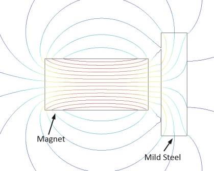
Figure 1: Mild Steel Example
B is in (Gauss) Permeability (unit-less) External Field strength (Oersted)
Mild Steel Example:
Induced (Internal Field) = ~ 15,000 Gauss = (30) x 500 Oersted
The 15,000 Gauss field induced in the mild steel interacts with the applied magnetic field, and there is attraction.
In Figure 1, it can be observed how the Flux lines are denser in the steel, showing the induced field, as well as how the Flux Lines “bend” in the steel alloy. The steel’s magnetic properties bias or interact with the magnet’s magnetic flux lines (Field).
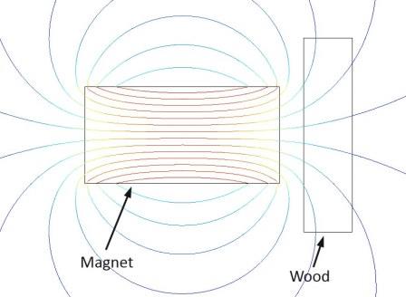
Figure 2: Wood Example
Induced (Internal Field) = 500 Gauss (1) x 500 Oersted
The only field in the wood is from the externally applied magnetic field and no new field is induced to interact with the applied field. No Attraction!
In Figure 2, it can be observed how the Flux Lines are not biased by the wood at all, and there is no induced field. The Flux Lines do not “bend” in the wood and pass through as if it is not there. There is no Field to Field interaction and no attraction.
The permeability of a material is not constant, and for a given temperature, it changes based on the intensity of the applied external magnetic field (H). The relative aspect of permeability is more apparent when illustrated with a graph depicting a material’s permeability relative to the applied external field. (Refer to Figure 3)
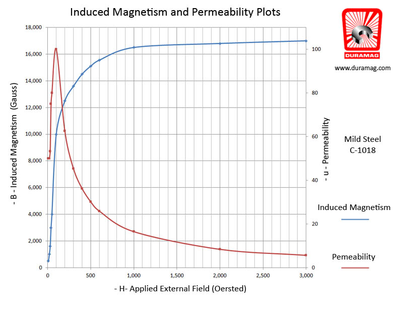
Figure 3
A material’s permeability is important, because it allows one to anticipate the performance of a magnet when used in a design. For instance, a customer may want to pick up automobile exhaust tubing with a magnetic end effector on a robot-arm. When the tube is made from an aluminized mild steel alloy the magnet handling device may work just fine; however, when the tube is 410 SS, the tube may be dropped. The force of attraction between the handling magnet and the tube is greater with the aluminized mild steel than the 410 SS because the mild steel has a higher permeability than the 410 SS.
Key Points:
- A ferrous material is attracted to a permanent magnet because the permanent magnet induces magnetism within the ferrous material. The permanent magnet’s field and the newly induced field in the ferrous part interact and attract.
- Magnetic Permeability is the characteristic of a material which represents the establishment of an induced internal magnetic field by an external magnetic field. The magnetic permeability is the proportionality between the Induced Field (B) and the applied Field Strength (H).

- A material’s permeability indicates how easily an external magnetic field can induce an internal field in the material. The higher the internal field, the higher the force of attraction.
- A material’s permeability is not constant and changes based on number a of factors. The effective permeability of a material can change with the temperature, how it was processed, the intensity of the applied drive field, humidity, etc.
Magnetics Deeper Entry into the Aerospace Industry
Receiving the AS9100C certification gave us the opportunity to demonstrate our knowledge and expertise in quality management. This certification reveals that we understand the best practices across the aerospace industry – one of the most rigorous and quality-driven industries in manufacturing. By integrating these practices throughout our own organization, we are able to further improve our current products and services.
Apple Watch Sport includes a plastic magnetic charger, not metal like the more expensive models

\
As users unbox their new Apple Watch units today, customers who bought the Sport version are receiving a bit of a surprise. The inductive charging cable bundled with Apple Watch Sport is actually made of plastic rather than the nice metal finishes of the more expensive stainless steel and gold watches.
The material is very similar to other Apple accessories which have white gloss exteriors. It’s unclear why the Sport does not get the fancier cable: it may be simply for cost-saving purposes to maximize Apple’s bottom line or it may be a design choice to better match the materials of the Watch itself.
Try Amazon Prime 30-Day Free Trial
The Sport charger was actually spotted in an Apple environment video although at the time it was unidentifiable. Apple’s public messaging did not make this distinction clear between the variants of Apple Watch, so some customers unwrapping their Apple Watch Sport purchases may be disappointed by this revelation.
X . IIIIII
HANDHELD SEISMOMETER
Introduction:
The handheld seismometer is designed to illustrate concepts of seismometry (sensing and recording the vibration or shaking of the ground generated by propagating seismic waves) and to be used as a simple seismometer for educational demonstrations and activities in seismology. The handheld seismometer is designed to be as visual and inexpensive as possible to best meet these objectives. Modifications could improve the sensitivity and performance characteristics of the seismometer, probably at the expense of simplicity and cost.
Theory:
Most seismometers detect ground motion using a mass which is suspended in some fashion by a spring. When the ground moves (say in an up and down or vertical motion), the seismometer's frame also moves, but the mass tends to remain relatively steady because of inertia. The relative motion of the mass with respect to the frame (and thus the ground) is then converted to an electrical signal (voltage variations with time) using a capacitor plate, a galvanometer or a magnet and coil assembly. Seismometers are usually sensitive to one component (direction) of ground motion (vertical or horizontal) and thus three components are used to completely characterize the seismic signals. A typical vertical component seismometer design is illustrated in Figure 1. Difficulties in understanding the theory and operation of such a design and of working seismometers are caused by: 1) the usual complexity of a modern, sensitive electromagnetic seismometer, 2) the difficulty of experimenting with the construction and components of the sensor, 3) the confusion caused by the fact that, although it appears in demonstrations (by physically moving the mass up and down) that it is the mass that is moving, it is actually the frame that moves and the mass tends to remain steady, 4) difficulty in understanding the electromagnetic sensor (transducer) theory and operation, and, 5) seismometers are usually expensive instruments enclosed in a case to improve performance and protect the mechanism, making it difficult for students, educators and other non-seismologists to obtain and experiment with the instrument.
The handheld seismometer solves some of these difficulties by being simple, visible and inexpensive to build. Principles of seismometry, including electromagnetic sensing using a magnet and coil, simple harmonic motion of the spring and mass system, damping and recording the seismic signal, can be easily demonstrated. One of the most effective demonstrations, is to simply hold the seismometer in one's hands and then "shake it" by moving the base up and down and noting the output. The seismometer can also be used on a tabletop for manual experimentation.
The magnet and coil sensor operates by measuring the change of the magnetic field by the amount of voltage produced in the surrounding coil. The sensor characteristics (primarily its sensitivity) are controlled by the strength of the magnet, the number of turns of wire in the coil and the distance of the magnet from the coil. Once the sensor is constructed, it is easy to demonstrate that the electrical output of the sensor is approximately proportional to the velocity of motion of the mass with respect to the coil. Alternatively, a more effective way to introduce the electromagnetic sensor used in many seismographs is to use a magnet and coil apparatus (Figure 2). One can use the magnet and coil to illustrate the generation of a current or voltage in the coil that is caused by the motion of a magnetic field. Connect the ends of the magnet wire from the coil to the simple seismometer amplifier circuit and the Vernier Serial Box Interface or to a digital multimeter. Hold the magnet inside the coil. Note that if the magnet is held steady, the output of the electrical signal is near zero (or a constant). When the magnet is moved up and down, a voltage is produced. When the magnet is moved rapidly, a larger voltage is generated. Note that moving the magnet up and down within the coil produces alternating positive and negative signals representing the relative motion of the magnet as compared to the coil.
Constructing the Handheld Seismometer:
Construction details and parts are provided on the attached diagram (Figure 3) and list. Figure 4 is a photo of a completed handheld seismometer.
Using the Handheld Seismometer:
The seismometer can be connected to a recording device in a variety of ways. The amplifier circuit and Vernier SBI (see option number 4 in the "viewing the output signal" section on the parts list, Table 1) is recommended because it provides a visual output of a seismogram on a computer. One can even save the seismograms for later use and for comparison of different shaking sequences. The computer display also aids in developing understanding of data acquisition and analysis concepts. An effective sequence is:
1. Hold the magnet assembly inside the coil to show that the output signal is not directly related to displacement (position in a vertical direction) but to relative motion (actually approximately proportional to velocity) of the mass with respect to the coil. Alternatively, use the separate magnet and coil assembly and procedure (described above) to illustrate the electromagnetic coupling.
2. With the mass suspended from the spring (as shown in Figure 3) and no oil in the container (no damping), cause the mass to move up and down to illustrate simple harmonic motion. Note that here is a "natural frequency" of the oscillation. Measure the period (1/frequency) of oscillation and note the sinusoidal characteristics of the signal.
3. Repeat the steps in number 2 with oil in the container for damping. This is the standard operating set-up for the seismometer.
4. Illustrate an incoming seismic wave and movement of the base (normally attached to the ground) by vibrating the seismometer vertically in your hands. Experiment with a "single pulse" input and a longer duration, more complex input (similar to the series of seismic waves produced by an earthquake source and wave propagation effects through the Earth from the source to the seismograph). See attached sample output of the handheld seismometer, Figure 5.
The handheld seismometer could be placed on the ground or floor to record small ground motion from nearby footsteps, or local seismic noise (such as generated by traffic) or weight drop experiments. However, several factors reduce the effectiveness of the handheld seismometer in this application. These factors include: the relatively low sensitivity of the seismometer; the high frequency of typical nearby sources, particularly on a concrete floor; the damping of the seismometer (which has positive effects as described above) which reduces the sensitivity, particularly for high frequency (³ 10 Hz) signals; and a high frequency resonance (unstable oscillation) of the suspended spring-mass system which is caused primarily by horizontal shaking.
To illustrate the recording of different size signals (different levels of ground motion), hold the seismometer in your hands and move it very slightly upwards. Next, move it moderately and then significantly upward. The three different sized motions of the seismometer base should be visibly distinct and will produce three different sized output pulses. Note that the seismometer output is proportional to the size of the input shaking. Because of this characteristic, the output of the seismometer (a seismogram) can be used to determine the level of ground shaking of the location of the seismometer. Stronger shaking will be generated by larger magnitude earthquakes. The level of shaking at a particular location is also controlled by the distance of the seismograph from the earthquake.
The handheld seismometer can also be used to illustrate common data recording principles. Note that while holding the handheld seismometer as steady as possible, there is still some shaking and therefore a small signal on the output record. Because there is no specific source (intentional shaking of the seismometer or earthquake–generated ground motion) during this time interval, we consider the output signal to be background "noise." Note that a small tap (a specific source of shaking) on the base of the seismometer may not produce a signal that is visible above the noise that is being continuously recorded. Because of the presence of background noise on the seismograph, small signals or signals from distant earthquakes are sometimes not visible on the seismogram because amplitudes (levels of shaking or height of the signal on the seismogram) of the signal may be smaller than the noise level. Furthermore, the presence of background noise encourages seismologists to find relatively quiet (low background noise) sites for locating seismographs. Sometimes ground shaking is too large to be accurately recorded by a seismograph. This situation can easily be illustrated with the handheld seismometer by moving the base rapidly by a large impulse upwards. If the motion is large enough, the suspended mass will hit the top or bottom of the container or the recording equipment will "saturate" because a voltage that is too large to be recorded by the interface (analog to digital converter) or recording software is generated. In this case, the top (or bottom, or both) of the recorded signal will be truncated or "clipped." When the signal is clipped, the maximum amplitudes of the ground shaking will not be accurately recorded, and the signal will be distorted in the time interval where clipping occurs. Both the noise and clipping problems, from too small or too large levels of ground motion, occur commonly in actual recordings of earthquakes by seismographs.
5. Demonstrate the components of a seismograph: mass and spring that sense the ground motion; magnet and coil sensor that converts the relative motion into an electrical signal that can be recorded; amplifier; digitizer (computer interface, Vernier SBI); recorder (computer and software). Note that an absolute time base, usually provided by an accurate chronometer or clock synchronized with universal time, is missing from this assembly. Such an absolute time base is usually included in a research-quality seismograph to provide earthquake monitoring capability.
Viewing the Output Signal:
A visual record or permanent recording of the output can be accomplished by a variety of methods including:
1. Directly to a strip chart recorder.
2. Directly to an oscilloscope.
3. Connect to a digital voltage meter (VOM; also called a multimeter or volt meter). Digital display will display movement and alternating positive and negative voltages.
4. An inexpensive and effective method to view the output signal of the magnet and coil assembly or the handheld seismometer is to utilize an amplifier circuit and an analog (with needle and dial scales; use 5 volt DC scale) multimeter. The amplifier circuit (Figures 6 and 7; Table 2) can be constructed (in about one hour after all parts are obtained; wire cutter/stripper and small needle-nose pliers are useful, although not required for assembly) using readily available parts for less than $20. An analog multimeter (or VOM or volt meter) can be purchased for less then $20. The output of the magnet and coil or handheld seismometer is very visible from movements of the needle on the multimeter (the DC offset feature of the amplifier circuit centers the needle, when there is no motion and therefore no signal from the magnet and coil, at about +2 volts). Motion of the magnet relative to the coil causes the needle to move back and forth on the multimeter scale. Small velocity motion of the magnet produces small deflections of the multimeter needle. Large velocity motion produces large deflections of the needle. Photographs of the amplifier circuit are provided in Figures 8 and 9.
5. Through amplifier interface circuit (see Simple Seismograph description; the amplifier interface circuit used in the Simple Seismograph activity is nearly identical to the amplifier and DC offset circuit that is described here) and Vernier Serial Box Interface (SBI, digitizer) to Vernier data logger software (LoggerPro) on a Mac or Win/DOS computer
Table 1. Handheld Seismometer Parts List(1)
Item
|
Number
|
Description
|
Approximate Price
|
1.
|
1
|
Spring (Servalite #59, Ace Hardware)(2)
|
$1.65
|
2.
|
2
|
5" x 1/4"(3) Eyebolts ($0.59 each)
|
$1.18
|
3.
|
4
|
1/4" nuts ($0.04 each)
|
$0.16
|
4.
|
1
|
Wood block ~ 25 cm long(4); 2 x 4 or 1" thick shelf board
|
$0.50
|
5.
|
1
|
Clear plastic container (Anchor Hoching Klear Stor, 236 ml (8 oz), cylindrical container, ~ 11 cm high by 5.5 cm diameter, with white plastic cap, available at Target)(5)
|
$1.14
|
6.
|
2
|
40 cm long 1/2" inside diameter PVC pipe(6)
|
$0.35
|
7.
|
1
|
11.5 cm long 1/2" inside diameter PVC pipe
|
$0.06
|
8.
|
2
|
1/2" PVC 'T' joints ($0.39 each)
|
$0.78
|
9.
|
2
|
1/2" PVC 'Elbow' joints ($0.29 each)
|
$0.58
|
10.
|
1
|
Magnet wire (#278-1345, Radio Shack, 3 rolls at $3.59, use thin wire)
|
$1.20
|
11.
|
2
|
Round Magnets (#64-188, Radio Shack, 6 magnets at $1.45)
|
$0.60
|
12.
|
2
|
#10 x 1" Machine Screws ($0.04 each)
|
$0.08
|
13.
|
4
|
1/4" washers ($0.02 each)(7)
|
$0.08
|
14.
|
2
|
3/8" wachers ($0.05 each)
|
$0.10
|
15.
|
6
|
11/16" washers ($0.55 each) (mass of each washer ~ 25 g)
|
$3.30
|
16.
|
~ 300 ml
|
Vegetable oil or mineral oil
|
$0.20
|
17.
|
1
|
1/4" diameter plastic straw(8)
|
-
|
(1)The Handheld Seismometer has been designed primarily for demonstration purposes and to be as simple and inexpensive as possible and to use readily-available parts. Its performance and appearance could be improved with a more complex and expensive design. Many parts could be substituted.
(2)Other, relatively weak springs will also work, but may require an adjustment in the mass and length of the long PVC pipe pieces. The Servalite #59 spring is about 12 cm long and 1.5 cm diameter and has a 1.5 cm attachment ring at each end. The spring has a 3 cm stretch with a 200g mass suspended. Spring available at Ace Hardware and other hardware stores.
(3)I apologize for the non-metric units. However, wood and hardware items available in the United States
(4)Nearly any small block of wood will work as long as it is thick enough to accept the mounting screws, wide enough to provide stability, and about 25 cm long to allow mounting of the PVC 'T' joints sufficiently far apart.
(5)Other containers could be substituted with suitable design changes. Diameter of the Klear Stor 236 ml container is appropriate for the mass, constructed from washers, that is used here. The clear container allows the mass and magnet to be seen during shaking. The 5.5 cm diameter allows 200-400 turns of fine magnet wire to be wound for the coil. Apply ~ 3 cm wide strip of two-sided tape to container before winding magnet wire. Be sure to scrape the coating off of the ends of the magnet wire so that electrical connection is possible. One can also add small alligator clips to the ends of the magnet wire for convenience in connecting to recording device.
(6)One-half inch PVC (plastic) pipe is inexpensive and available at most hardware stores. It is 1/2" inside diameter. CPVC pipe is also available but is more expensive because it is designed for hot water, and it is also more flexible, making it less suitable for use in the frame. The outside diameters of 1/2" PVC and 1/2" CPVC pipe also differ, so they are not interchangeable.
(7)Washers are labeled by the inside diameter. Two of the 1/4" washers are used for mounting the PVC 'T' joints to the wood base. Drill a 1/4" hole in the PVC 'T' joint.
(8)Straws have slightly different diameters. Most plastic straws available at fast-food restaurants have a diameter slightly greater than 1/4" and thus fit over the threaded 1/4" eyebolt. The straw provides for relatively low friction if the eyebolt comes in contact with the edges of the hole in the plastic cap during shaking.
Table 2. Parts List – Amplifier and DC Offset Circuit
Parts for Amplifier and DC Offset Circuit (parts are available at Radio Shack or electronics suppliers. If you have difficulty finding the ICL 7660 IC, contact Mouser Electronics, 800-346-6873, www.mouser.com).
1 – ICL 7660 Integrated Circuit (IC)
1 – IC 741 IC – Op Amp
3 – 10 mF Capacitors
1 – 47k Ohm resistor (yellow-violet-orange)
1 – 180k Ohm resistor (brown-grey-yellow)
1 – 2.2k Ohm resistor (red-red-red) (use 1k Ohm resistor for about 2x higher gain and, therefore, a larger signal on the multimeter; recommended)
1 – 1 Meg Ohm potentiometer (variable resistor)
10 – wire leads [6 long (10 cm) jumper wires, 4 short (6 cm) jumper wires; #22 insulated solid copper wire, stripped (~ 1 cm) at both ends]
4 – Alligator clip test lead wires
1 – experimenter's board (Radio Shack Part #276-175)
1 – 6 volt lantern battery
3 – Circular magnets (Radio Shack Part #64-188)
Figure 1. Schematic diagram of a seismometer. Ground motion causes the base and frame of the seismometer. The mass, suspended by the spring and boom, tends to stay in one place because of inertia. The relative motion of the base as compared to the mass is recorded as the output of the seismometer.
Figure 2. Photo of magnet and coil used to illustrate electromagnetic coupling used in a seismometer. A small plastic container wrapped with magnet wire (100 or more turns; place two-sided tape on the outside of the container to help hold the magnet wire) forms the coil. Solder alligator clip leads to the ends of the wire. The magnet (one or more circular magnets) is attached to a bolt for convenience in holding the magnet and moving the magnet inside the coil. For the coil assembly shown here, a 118 mL (4 oz.) container (Rubbermaid "Servin' Saver") was used. Fine gauge magnet wire was wrapped on the outside of the container. Rubber bands were used to keep the wire from unwinding.
Figure 3. Diagram showing construction details for the handheld seismometer. Parts are listed in Table 1.
Figure 4. Photo of completed handheld seismometer.
Figure 5. Sample output from the handheld seismometer using the amplifier interface circuit (see Simple Seismograph activity), Vernier software SBI interface and Logger Pro display software. The input signal (shaking of the seismometer held in one's hands) was a single impulse (one sudden upward motion of the seismometer's base) followed by a few seconds of shaking the seismometer up and down.
Figure 6. Amplifier and DC offset circuit diagram.
Figure 7. Construction details for the amplifier and DC offset circuit. Parts are listed in Table 2. Photographs illustrating the completed circuit and use of the circuit with the magnet and coil assembly are shown in Figures 8 and 9.
Figure 8. Close-up view of completed amplifier and DC offset circuit. Components and jumper wires are placed in the "experimenter's board" using the plans shown in Figure 7.
Figure 9. Photograph of amplifier circuit connected to magnet and coil assembly to provide input signal and multimeter to view output signal. A 6 volt battery is used to provide power for the amplifier circuit. Alligator clip test leads are used to connect the battery to the circuit and the output of the circuit to the multimeter. It is useful to leave the circuit uncovered and make the attachments with the test leads to illustrate the use of electronic circuits. Circuits that are similar in concept, but usually much more complicated, form the basis for the many electronic products (computers, televisions, CD players, VCRs, radios, etc.) that we use daily.
Your post is very great.I read this post. It’s very helpful. You can check more about Adapalene and Benzoyl Peroxide manufacturer here
BalasHapus