Fan (machine)

A fan is a machine used to create flow within a fluid, typically a gas such as air. The fan consists of a rotating arrangement of vanes or blades which act on the fluid. The rotating assembly of blades and hub is known as an impeller, a rotor, or a runner. Usually, it is contained within some form of housing or case.[2] This may direct the airflow or increase safety by preventing objects from contacting the fan blades. Most fans are powered by electric motors, but other sources of power may be used, including hydraulic motors and internal combustion engines.
Fans produce flows with high volume and low pressure (although higher than ambient pressure), as opposed to compressors which produce high pressures at a comparatively low volume. A fan blade will often rotate when exposed to a fluid stream, and devices that take advantage of this, such as anemometers and wind turbines, often have designs similar to that of a fan.
Typical applications include climate control and personal thermal comfort (e.g., an electric table or floor fan), vehicle engine cooling systems (e.g., in front of a radiator), machinery cooling systems (e.g., inside computers and audio power amplifiers), ventilation, fume extraction, winnowing (e.g., separating chaff of cereal grains), removing dust (e.g. in a vacuum cleaner), drying (usually in combination with a heat source) and to provide draft for a fire.
While fans are often used to cool people, they do not actually cool air (if anything, electric fans warm it slightly due to the warming of their motors), but work by evaporative cooling of sweat and increased heat convection into the surrounding air due to the airflow from the fans. Thus, fans may become ineffective at cooling the body if the surrounding air is near body temperature and contains high humidity. During periods of very high heat and humidity, governments actually advise against the use of fans.


Household electric "box"
fan with a propeller style blade A standard clip-fan
The punkah fan was used in India about 500 BCE. It was a handheld fan made from bamboo strips or other plant fibre, that could be rotated or fanned to move air. During British rule, the word came to be used by Anglo-Indians to mean a large swinging flat fan, fixed to the ceiling, and pulled by a servant, called the punkawallah.

Patent drawing for a Fan Moved by Mechanism, 27 November 1830
In the 17th century, the experiments of scientists like Otto von Guericke, Robert Hooke and Robert Boyle, established the basic principles of vacuum and airflow. The English architect Sir Christopher Wren applied an early ventilation system in the Houses of Parliament that used bellows to circulate air. Wren's design would be the catalyst for much later improvement and innovation. The first rotary fan used in Europe was for mine ventilation during the 16th century, as illustrated by Georg Agricola (1494–1555).[5]
John Theophilus Desaguliers, a British engineer, demonstrated a successful use of a fan system to draw out stagnant air from coal mines in 1727 and soon afterwards he installed a similar apparatus in Parliament.[6] Good ventilation was particularly important in coal mines to reduce casualties from asphyxiation. The civil engineer John Smeaton, and later John Buddle installed reciprocating air pumps in the mines in the North of England. However, this arrangement was not ideal as the machinery was liable to breaking down.
Steam
With the advent of practical steam power, fans could finally be used for ventilation. In 1837 William Fourness of England installed a steam-driven fan at Leeds.[7] In 1849 a 6 m radius steam driven fan, designed by William Brunton, was made operational in the Gelly Gaer Colliery of South Wales. The model was exhibited at the Great Exhibition of 1851. Also in 1851 David Boswell Reid, a Scottish physician, installed four steam powered fans in the ceiling of St George's Hospital in Liverpool, so that the pressure produced by the fans would force the incoming air upward and through vents in the ceiling.[8][9] Improvements in the technology were made by James Nasmyth, Frenchman Theophile Guibal and J. R. Waddle.[10]Electrical
Between the years 1882 and 1886, New Orleans, LA resident Schuyler Skaats Wheeler invented a fan powered by electricity.[11] It was commercially marketed by the American firm Crocker & Curtis electric motor company. In 1882, Philip Diehl developed the world's first electric ceiling fan. During this intense period of innovation, fans powered by alcohol, oil, or kerosene were common around the turn of the 20th century. In 1909, KDK of Japan pioneered the invention of mass-produced electric fans for home use. In the 1920s, industrial advances allowed steel fans to be mass-produced in different shapes, bringing fan prices down and allowing more homeowners to afford them. In the 1930s, the first art deco fan (the "swan fan") was designed. By the 1940s, Crompton Greaves of India became the world's largest manufacturer of electric ceiling fans mainly for sale in India, Asia and the Middle East. By the 1950s, table and stand fans were manufactured in colors that were bright and eye catching.Window and central air conditioning in the 1960s caused many companies to discontinue production of fans.[12] But in the mid 1970s, with an increasing awareness of the cost of electricity and the amount of energy used to heat and cool homes, turn-of-the-century styled ceiling fans became immensely popular again as both decorative and energy efficient units.
In 1998, Walter K. Boyd invented the HVLS ceiling fan. It was a slow moving fan with an eight-foot diameter. Due to its size, the fan moved a large column of air and continuously mixed fresh air with the stale air inside. They are used in many industrial and agricultural settings, because of their energy efficiency.[13]
Types
Revolving blade fans are made in a wide range of designs. They are used on the floor, table, desk, or hung from the ceiling. They can also be built into a window, wall, roof, chimney, etc. Most electronic systems such as computers include fans to cool circuits inside, and in appliances such as hair dryers and portable space heaters and mounted/installed wall heaters. They are also used for moving air in air-conditioning systems, and in automotive engines, where they are driven by belts or by direct motor. Fans used for comfort create a wind chill by increasing the heat transfer coefficient, but do not lower temperatures directly. Fans used to cool electrical equipment or in engines or other machines do cool the equipment directly by forcing hot air into the cooler environment outside the machine.

There are three main types of fans used for moving air, axial, centrifugal (also called radial) and cross flow (also called tangential). The American Society of Mechanical Engineers Performance Testing Code 11 (PTC)[14] provides standard procedures for conducting and reporting tests on fans, including those of the centrifugal, axial, and mixed flows.
Axial-flow
Axial-flow fans have blades that force air to move parallel to the shaft about which the blades rotate. This type of fan is used in a wide variety of applications, ranging from small cooling fans for electronics to the giant fans used in wind tunnels. Axial flow fans are applied in air conditioning and industrial process applications. Standard axial flow fans have diameters from 300–400 mm or 1800 to 2000 mm and work under pressures up to 800 Pa. Special types of fans are used as low pressure compressor stages in aircraft engines. Examples of axial fans are:
- Table fan: Basic elements of a typical table fan include the fan blade, base, armature and lead wires, motor, blade guard, motor housing, oscillator gearbox, and oscillator shaft.[15] The oscillator is a mechanism that moves the fan from side to side. The armature shaft comes out on both ends of the motor, one end of the shaft is attached to the blade and the other is attached to the oscillator gearbox. The motor case joins to the gearbox to contain the rotor and stator. The oscillator shaft combines to the weighted base and the gearbox. A motor housing covers the oscillator mechanism. The blade guard joins to the motor case for safety.
- Ceiling fan: A fan suspended from the ceiling of a room is a ceiling fan. Most ceiling fans rotate at relatively low speeds and do not have blade guards. Ceiling fans can be found in both residential and industrial/commercial settings.
- In automobiles, a mechanical fan provides engine cooling and prevents the engine from overheating by blowing or drawing air through a coolant-filled radiator. The fan may be driven with a belt and pulley off the engine's crankshaft or an electric motor switched on or off by a thermostatic switch.
- Computer cooling fan for cooling electrical components
- Fans inside audio power amplifiers help to draw heat away from the electrical components.
- variable-pitch fan: A variable-pitch fan is used where precise control of static pressure within supply ducts is required. The blades are arranged to rotate upon a control-pitch hub. The fan wheel will spin at a constant speed. As the hub moves toward the rotor, the blades increase their angle of attack and an increase in flow results.
Centrifugal
Often called a "squirrel cage" (because of its general similarity in appearance to exercise wheels for pet rodents) or "scroll fan", the centrifugal fan has a moving component (called an impeller) that consists of a central shaft about which a set of blades, or ribs, are positioned. Centrifugal fans blow air at right angles to the intake of the fan, and spin the air outwards to the outlet (by deflection and centrifugal force). The impeller rotates, causing air to enter the fan near the shaft and move perpendicularly from the shaft to the opening in the scroll-shaped fan casing. A centrifugal fan produces more pressure for a given air volume, and is used where this is desirable such as in leaf blowers, blowdryers, air mattress inflators, inflatable structures, climate control, and various industrial purposes. They are typically quieter than comparable axial fans.
Cross-flow


The flow within a cross-flow fan may be broken up into three distinct regions: a vortex region near the fan discharge, called an eccentric vortex, the through-flow region, and a paddling region directly opposite. Both the vortex and paddling regions are dissipative, and as a result, only a portion of the impeller imparts usable work on the flow. The cross-flow fan, or transverse fan, is thus a two-stage partial admission machine. The popularity of the crossflow fan in the HVAC industry comes from its compactness, shape, quiet operation, and ability to provide high pressure coefficient. Effectively a rectangular fan in terms of inlet and outlet geometry, the diameter readily scales to fit the available space, and the length is adjustable to meet flow rate requirements for the particular application.
Common household tower fans are also cross-flow fans. Much of the early work focused on developing the cross-flow fan for both high and low-flow-rate conditions, and resulted in numerous patents. Key contributions were made by Coester, Ilberg and Sadeh, Porter and Markland, and Eck. One phenomenon particular to the cross-flow fan is that, as the blades rotate, the local air incidence angle changes. The result is that in certain positions the blades act as compressors (pressure increase), while at other azimuthal locations the blades act as turbines (pressure decrease).
Uncommon types of fans
Bellows
Bellows are also used to move air, although not generally considered fans. A hand-operated bellows is essentially a bag with a nozzle and handles, which can be filled with air by one movement, and the air expelled by another. Typically it would comprise two rigid flat surfaces hinged at one end, where a nozzle is fitted, and with handles at the other..svg)
The sides of the surfaces are joined by a flexible and air-proof material such as leather; the surfaces and joining material comprise a bag sealed everywhere but at the nozzle. (The joining material typically has a characteristic pleated construction that is so common that similar expanding fabric arrangements not used for moving air, such as on a folding camera, are called bellows.) Separating the handles expands the bag, which fills with air; squeezing them together expels the air. A simple valve (e.g., a flap) may be fitted so that air enters without having to come from the nozzle, which may be close to a fire.
Bellows produce a directed pressurized stream of air; the airflow volume is typically low with moderate pressure. They are an older technology, used mainly to produce a strong and directed airflow unlike non-electric bladed mechanical fans, before the introduction of electricity.
- A single-acting bellows will only produce airflow during the exhaust stroke.
- A double-acting bellows is a pair of bellows capable of blowing out air from one while inhaling air into the other, but airflow still temporarily ceases when the stroke direction is reversed.
- Combining multiple bellows at third-cycle or quarter-cycle arrangements on a crank arm allows for nearly continuous airflow from several bellows at once; each is in a different phase of inhaling and exhausting during the cycle.
Coandă effect

Convective
Differences in air temperature will affect the density of air and can be used to induce air circulation through the mere act of heating or cooling an air mass. This effect is so subtle and works at such low air pressures that it does not appear to fit the definition of a fan technology. However, prior to the development of electricity, convective airflow was the primary method of inducing airflow in living spaces. Old fashioned oil and coal furnaces were not electric and operated simply on the principle of convection to move the warm air. Very large volume air ducts were sloped upwards away from the top of the furnace towards floor and wall registers above the furnace. Cool air was returned through similar large ducts leading to the bottom of the furnace. Older houses from before electrification often had open duct grilles leading from the ceiling of a lower level to the floor of an upper level, to allow convective airflow to slowly rise up the building from one floor to the next. Outhouses commonly rely on a simple enclosed air channel in a corner of the structure to exhaust offensive odors. Exposed to sunlight, the channel is warmed and a slow convective air current is vented out the top of the building, while fresh air enters the pit through the seat hole.Electrostatic
An electrostatic fluid accelerator propels airflow by inducing motion in airborne charged particles. A high voltage electric field (commonly 25,000 to 50,000 volts) formed between exposed charged anode and cathode surfaces is capable of inducing airflow through a principle referred to as ionic wind. The airflow pressure is typically very low but the air volume can be large. However, a sufficiently high voltage potential can also cause the formation of ozone and nitrogen oxides, which are reactive and irritating to mucous membranes.Noise
Fans generate noise from the rapid flow of air around blades and obstacles, and sometimes from the motor. Fan noise has been found to be roughly proportional to the fifth power of fan speed; halving speed reduces noise by about 15 dB.Drive methods


Internal combustion engines sometimes drive an engine cooling fan directly, or may use a separate electric motor.


In machines with a rotating part, the fan is often connected to it rather than being powered separately. This is commonly seen in motor vehicles with internal combustion engines, where the fan is connected to the drive shaft directly or through a belt and pulleys. A common configuration is a dual-shaft motor, where one end of the shaft drives a mechanism, while the other has a fan mounted on it to cool the motor itself. Window air conditioners commonly use a dual-shaft fan to operate separate blowers for the interior and exterior parts of the device.
Where electrical power or rotating parts are not available, fans may be drive by other methods. High-pressure gases such as steam can be used to drive a small turbine, and high-pressure liquids can be used to drive a pelton wheel, which can provide the rotational drive for a fan. Large, slow-moving energy sources such as a flowing river can also power a fan using a water wheel and a train of gears or pulleys.

Turbomachinery

Turbomachinery, in mechanical engineering, describes machines that transfer energy between a rotor and a fluid, including both turbines and compressors. While a turbine transfers energy from a fluid to a rotor, a compressor transfers energy from a rotor to a fluid.
These two types of machines are governed by the same basic relationships including Newton's second Law of Motion and Euler's pump and turbine equation for compressible fluids. Centrifugal pumps are also turbomachines that transfer energy from a rotor to a fluid, usually a liquid, while turbines and compressors usually work with a gas.
The first use of turbomachines were technically water wheels between the 3rd and 1st century BCE, credited to the people in the Mediterranean region (see more at water wheel). The first real modern turbomachines did not appear until the late 1880’s. It was not until the industrial revolution, however, steam power started to be utilized with reciprocating engines and turbines, which opened up the potential of steam power. The first impulse type turbine was created by Carl Gustaf de Laval in 1883. This was closely followed by the first practical reaction type turbine in 1884, built by Charles Parsons. Parsons’ first design was a multi-stage axial-flow unit, which George Westinghouse acquired and began manufacturing in 1895, while General Electric acquired de Laval’s designs in 1897. Since then, development has skyrocketed from Parsons’ early design, producing 0.746 kW, to modern nuclear steam turbines producing upwards of 1500 MW. Today, steam turbines account for roughly 90% of electrical power generated in the United States. The first patents for gas turbines were filed in 1791 by John Barber. Then the first functioning industrial gas turbines were used in the late 1890’s to power street lights (Meher-Homji, 2000).
Classification

A steam turbine from MAN SE subdidiary MAN Turbo
In general, the two kinds of turbomachines encountered in practice are open and closed turbomachines. Open machines such as propellers, windmills, and unshrouded fans act on an infinite extent of fluid, whereas, closed machines operate on a finite quantity of fluid as it passes through a housing or casing.[2]
Turbomachines are also categorized according to the type of flow. When the flow is parallel to the axis of rotation, they are called axial flow machines, and when flow is perpendicular to the axis of rotation, they are referred to as radial (or centrifugal) flow machines. There is also a third category, called mixed flow machines, where both radial and axial flow velocity components are present.[2]
Turbomachines may be further classified into two additional categories: those that absorb energy to increase the fluid pressure, i.e. pumps, fans, and compressors, and those that produce energy such as turbines by expanding flow to lower pressures. Of particular interest are applications which contain pumps, fans, compressors and turbines. These components are essential in almost all mechanical equipment systems, such as power and refrigeration cycles.[2][3]
| machine type → group ↓ | machinery | combinations of power and machinery | engines |
|---|---|---|---|
| open turbomachine | propeller | wind turbines | |
| hydraulic fluid machinery (≈ incompressible fluids) | centrifugal pumps turbopumps and fans | Fluid couplings and clutches (hydrodynamic gearbox); Voith Turbo-Transmissions; pump-turbines (in pumped-storage hydroelectricity) | water turbines |
| thermal turbomachinery (compressible fluid) | compressors | gas turbines (inlet of GT consists of a compressor) | steam turbines ← turbine jet engines |
Turbomachines
Definition
Any devices that extracts energy from or imparts energy to a continuously moving stream of fluid can be called a Turbomachine. Elaborating, a turbomachine is a power or head generating machine which employs the dynamic action of a rotating element, the rotor; the action of the rotor changes the energy level of the continuously flowing fluid through the machine. Turbines, compressors and fans are all members of this family of machines.[4]
In contrast to positive displacement machines (particularly of the reciprocating type which are low speed machines based on the mechanical and volumetric efficiency considerations), the majority of turbomachines run at comparatively higher speeds without any mechanical problems and volumetric efficiency close to one hundred percent.[5]
Categorization
Energy conversion
- Absorb power to increase the fluid pressure or head (ducted Fans, compressors and pumps).
- Produce power by expanding fluid to a lower pressure or head (hydraulic, steam and gas turbines).
Fluid flow
Turbomachines can be categorized on the basis of the nature of flow path through the passage of the rotor:[6]
Axial Turbomachine's Velocity Diagram[1]
A Kaplan turbine is an example of an axial flow turbine.
In the figure:
- U = Blade velocity,
- Vf = Flow velocity,
- V = Absolute velocity,
- Vr = Relative velocity,
- Vw = Tangential or Whirl component of velocity.

Radial Turbomachine's Velocity Diagram[1]
A centrifugal pump is an example of a radial flow turbine.
In the figure:
- U = Blade velocity,
- Vf = Flow velocity,
- V = Absolute velocity,
- Vr = Relative velocity,
- Vw = Tangential or Whirl component of velocity.
A Francis turbine is an example of a mixed-flow turbine.
Physical action
Turbomachines can finally be classified on the relative magnitude of the pressure changes that take place across a stage:
An Impulse Turbomachine Stage[1]
Newton's second law describes the transfer of energy. Impulse turbomachines do not require a pressure casement around the rotor since the fluid jet is created by the nozzle prior to reaching the blading on the rotor.
A Pelton wheel is an impulse design.

A Reaction Turbomachine Stage[1]
Newton's third law describes the transfer of energy for reaction turbines. A pressure casement is needed to contain the working fluid. For compressible working fluids, multiple turbine stages are usually used to harness the expanding gas efficiently.
Most turbomachines use a combination of impulse and reaction in their design, often with impulse and reaction parts on the same blade.
Dimensionless ratios to describe turbomachinery

- Pressure range ψ
- Flow number φ (including delivery or volume number called)
- Performance numbers λ
- Run number σ
- Diameter Number δ
Applications
Power Generation
Hydro electric- Hydro-electric turbomachinery uses potential energy stored in water to flow over an open impeller to turn a generator which creates electricitySteam turbines- Steam turbines used in power generation come in many different variations. The overall principle is high pressure steam is forced over blades attached to a shaft, which turns a generator. As the steam travels through the turbine, it passes through smaller blades causing the shaft to spin faster, creating more electricity.
Gas turbines- Gas turbines work much like steam turbines. Air is forced in through a series of blades that turn a shaft. Then fuel is mixed with the air and causes a combustion reaction, increasing the power. This then causes the shaft to spin faster, creating more electricity.
Windmills- Also known as a wind turbine, windmills are increasing in popularity for their ability to efficiently use the wind to generate electricity. Although they come in many shapes and sizes, the most common one is the large three-blade. The blades work on the same principle as an airplane wing. As wind passes over the blades, it creates an area of low and high pressure, causing the blade to move, spinning a shaft and creating electricity. It is most like a steam turbine, but work with an infinite supply of wind.
Marine
Steam turbine- Steam turbines in marine applications are very similar to those in power generation. The few differences between them are size and power output. Steam turbines on ships are much smaller because they don’t need to power a whole town. They aren’t very common because of their high initial cost, high specific fuel consumption, and expensive machinery that goes with it.Gas turbines- Gas turbines in marine applications are becoming more popular due to their smaller size, increased efficiency, and ability to burn cleaner fuels. They run just like gas turbines for power generation, but are also much smaller and do require more machinery for propulsion. They are most popular in naval ships as they can be at a dead stop to full power in minutes (Kayadelen, 2013), and are much smaller for a given amount of power. Flow of air through a turbocharger and engine
Auto
Turbochargers- Turbochargers are one of the most popular turbomachines. They are used mainly for adding power to engines by adding more air. It combines both forms of turbomachines. Exhaust gases from the engine spin a bladed wheel, much like a turbine. That wheel then spins another bladed wheel, sucking and compressing outside air into the engine.
Superchargers- Superchargers are used for engine-power enhancement as well, but only work off the principle of compression. They use the mechanical power from the engine to spin a screw or vein, some way to suck in and compress the air into the engine.
General
Pumps- Pumps are another very popular turbomachine. Although there are very many different types of pumps, they all do the same thing. Pumps are used to move fluids around using some sort of mechanical power, from electric motors to full size diesel engines. Pumps have thousands of uses, and are the true basis to turbomachinery (Škorpík, 2017).Air compressors- Air compressors are another very popular turbomachine. They work on the principle of compression by sucking in and compressing air into a holding tank. Air compressors are one of the most basic turbomachines.
Fans- Fans are the most general type of turbomachines. They work opposite of wind turbines. Mechanical power spins the blades, forcing air through them and forcing out. Basic desk-top fans to large turbofan airplane engines work this way.
Aerospace
Gas turbines- Aerospace gas turbines, or more commonly know jet engines, are the most common gas turbines. They are the most like power generation turbines because the electricity used on the airplane is from the turbines, while also providing the propulsion. These turbines are the smallest out of the industrial turbines, and are most often the most advanced.Partial list of turbomachine topics
Many types of dynamic continuous flow turbomachinery exist. Below is a partial list of these types. What is notable about these turbomachines is that the same fundamentals apply to all. Certainly there are significant differences between these machines and between the types of analysis that are typically applied to specific cases. This does not negate the fact that they are unified by the same underlying physics of fluid dynamics, gas dynamics, aerodynamics, hydrodynamics, and thermodynamics.Turboprop


A Fairchild F-27 representative of the 2nd generation of modern Rolls-Royce Dart turboprop powered propjet aircraft, after the initial success of the 1950s era Vickers Viscount.

An ATR-72, a typical modern turboprop aircraft.
A turboprop engine is a turbine engine that drives an aircraft propeller.[1] In contrast to a turbojet, the engine's exhaust gases do not contain enough energy to create significant thrust, since almost all of the engine's power is used to drive the propeller.
In its simplest form a turboprop consists of an intake, compressor, combustor, turbine, and a propelling nozzle. Air is drawn into the intake and compressed by the compressor. Fuel is then added to the compressed air in the combustor, where the fuel-air mixture then combusts. The hot combustion gases expand through the turbine. Some of the power generated by the turbine is used to drive the compressor. The rest is transmitted through the reduction gearing to the propeller. Further expansion of the gases occurs in the propelling nozzle, where the gases exhaust to atmospheric pressure. The propelling nozzle provides a relatively small proportion of the thrust generated by a turboprop.
Technological aspects

Exhaust thrust in a turboprop is sacrificed in favor of shaft power, which is obtained by extracting additional power (up to that necessary to drive the compressor) from turbine expansion. Owing to the additional expansion in the turbine system, the residual energy in the exhaust jet is low.[2][3][4] Consequently, the exhaust jet typically produces around or less than 10% of the total thrust,[5] a higher proportion of the thrust come from the propeller at low speeds and less at higher speeds.[6] Turboprops can have bypass ratios up to 50-100[7][8][9] although the propulsion airflow is less clearly defined for propellers than for fans.[10]
The propeller is coupled to the turbine through a reduction gear that converts the high RPM, low torque output to low RPM, high torque. The propeller itself is normally a constant speed (variable pitch) type similar to that used with larger reciprocating aircraft engines.[citation needed]
Unlike the small diameter fans used in turbofan jet engines, the propeller has a large diameter that lets it accelerate a large volume of air. This permits a lower airstream velocity for a given amount of thrust. As it is more efficient at low speeds to accelerate a large amount of air by a small degree than a small amount of air by a large degree,[11][12] a low disc loading (thrust per disc area) increases the aircraft's energy efficiency, and this reduces the fuel use.[13][14]
Propellers lose efficiency as aircraft speed increases, so turboprops are normally not used on high-speed aircraft[2][3][4] above Mach 0.6-0.7.[5] However, propfan engines, which are very similar to turboprop engines, can cruise at flight speeds approaching Mach 0.75. To increase propeller efficiency, a mechanism can be used to alter their pitch relative to the airspeed. A variable-pitch propeller, also called a controllable-pitch propeller, can also be used to generate negative thrust while decelerating on the runway. Additionally, in the event of an engine outage, the pitch can be adjusted to a vaning pitch (called feathering), thus minimizing the drag of the non-functioning propeller.[citation needed]
While most modern turbojet and turbofan engines use axial-flow compressors, turboprop engines usually contain at least one stage of centrifugal compression. Centrifugal compressors have the advantage of being simple and lightweight, at the expense of a streamlined shape.
While the power turbine may be integral with the gas generator section, many turboprops today feature a free power turbine on a separate coaxial shaft. This enables the propeller to rotate freely, independent of compressor speed.[15] Residual thrust on a turboshaft is avoided by further expansion in the turbine system and/or truncating and turning the exhaust 180 degrees, to produce two opposing jets. Apart from the above, there is very little difference between a turboprop and a turboshaft.

A Rolls-Royce RB.50 Trent on a test rig at Hucknall, in March 1945

Kuznetsov NK-12M Turboprop, on a Tu-95

Alan Arnold Griffith had published a paper on turbine design in 1926. Subsequent work at the Royal Aircraft Establishment investigated axial turbine designs that could be used to supply power to a shaft and thence a propeller. From 1929, Frank Whittle began work on centrifugal turbine designs that would deliver pure jet thrust.[16]
The world's first turboprop was designed by the Hungarian mechanical engineer György Jendrassik.[17] Jendrassik published a turboprop idea in 1928, and on 12 March 1929 he patented his invention. In 1938, he built a small-scale (100 Hp; 74.6 kW) experimental gas turbine.[18] The larger Jendrassik Cs-1, with a predicted output of 1,000 bhp, was produced and tested at the Ganz Works in Budapest between 1937 and 1941. It was of axial-flow design with 15 compressor and 7 turbine stages, annular combustion chamber and many other modern features. First run in 1940, combustion problems limited its output to 400 bhp. In 1941,the engine was abandoned due to war, and the factory was turned over to conventional engine production. The world's first turboprop engine that went into mass production was designed by a German engineer, Max Adolf Mueller, in 1942.[19]
The first mention of turboprop engines in the general public press was in the February 1944 issue of the British aviation publication Flight, which included a detailed cutaway drawing of what a possible future turboprop engine could look like. The drawing was very close to what the future Rolls-Royce Trent would look like.[20] The first British turboprop engine was the Rolls-Royce RB.50 Trent, a converted Derwent II fitted with reduction gear and a Rotol 7 ft 11 in (2.41 m) five-bladed propeller. Two Trents were fitted to Gloster Meteor EE227 — the sole "Trent-Meteor" — which thus became the world's first turboprop-powered aircraft, albeit a test-bed not intended for production.[21][22] It first flew on 20 September 1945. From their experience with the Trent, Rolls-Royce developed the Rolls-Royce Clyde, the first turboprop engine to be fully type certificated for military and civil use,[23] and the Dart, which became one of the most reliable turboprop engines ever built. Dart production continued for more than fifty years. The Dart-powered Vickers Viscount was the first turboprop aircraft of any kind to go into production and sold in large numbers.[24] It was also the first four-engined turboprop. Its first flight was on 16 July 1948. The world's first single engined turboprop aircraft was the Armstrong Siddeley Mamba-powered Boulton Paul Balliol, which first flew on 24 March 1948.[25]
The Soviet Union built on German World War II development by Junkers Motorenwerke, while BMW, Heinkel-Hirth and Daimler-Benz also developed and partially tested designs.[citation needed] While the Soviet Union had the technology to create the airframe for a jet-powered strategic bomber comparable to Boeing's B-52 Stratofortress, they instead produced the Tupolev Tu-95 Bear, powered with four Kuznetsov NK-12 turboprops, mated to eight contra-rotating propellers (two per nacelle) with supersonic tip speeds to achieve maximum cruise speeds in excess of 575 mph, faster than many of the first jet aircraft and comparable to jet cruising speeds for most missions. The Bear would serve as their most successful long-range combat and surveillance aircraft and symbol of Soviet power projection throughout the end of the 20th century. The USA would incorporate contra-rotating turboprop engines, such as the ill-fated twin-turbine Allison T40 — essentially a twinned up pair of Allison T38 turboprop engines driving contra-rotating propellers — into a series of experimental aircraft during the 1950s, with aircraft powered with the T40, like the Convair R3Y Tradewind flying boat never entering U.S. Navy service.
The first American turboprop engine was the General Electric XT31, first used in the experimental Consolidated Vultee XP-81.[26] The XP-81 first flew in December 1945, the first aircraft to use a combination of turboprop and turbojet power. The technology of the Allison's earlier T38 design evolved into the Allison T56, with quartets of the T56s being used to power the Lockheed Electra airliner, its military maritime patrol derivative the P-3 Orion, and the widely produced C-130 Hercules military transport aircraft. One of the most produced turboprop engines used in civil aviation is the Pratt & Whitney Canada PT6 engine.[citation needed]
The first turbine-powered, shaft-driven helicopter was the Kaman K-225, a development of Charles Kaman's K-125 synchropter, which used a Boeing T50 turboshaft engine to power it on 11 December 1951.[27]
Usage

Compared to turbofans, turboprops are most efficient at flight speeds below 725 km/h (450 mph; 390 knots) because the jet velocity of the propeller (and exhaust) is relatively low. Modern turboprop airliners operate at nearly the same speed as small regional jet airliners but burn two-thirds of the fuel per passenger.[28] However, compared to a turbojet (which can fly at high altitude for enhanced speed and fuel efficiency) a propeller aircraft has a lower ceiling.
The most common application of turboprop engines in civilian aviation is in small commuter aircraft, where their greater power and reliability offsets their higher initial cost and fuel consumption. Turboprop-powered aircraft have become popular for bush airplanes such as the Cessna Caravan and Quest Kodiak as jet fuel is easier to obtain in remote areas than avgas. Due to the high price of turboprop engines, they are mostly used where high-performance short-takeoff and landing (STOL) capability and efficiency at modest flight speeds are required.
Turboprop engines are generally used on small subsonic aircraft, but the Tupolev Tu-114 can reach 470 kt (870 km/h, 541 mph). Large military and civil aircraft, such as the Lockheed L-188 Electra and the Tupolev Tu-95, have also used turboprop power. The Airbus A400M is powered by four Europrop TP400 engines, which are the third most powerful turboprop engines ever produced, after the eleven megawatt-output Kuznetsov NK-12 and 10.4 MW-output Progress D-27.[citation needed]
Some commercial aircraft with turboprop engines include the Bombardier Dash 8, ATR 42, ATR 72, BAe Jetstream 31, Beechcraft 1900, Embraer EMB 120 Brasilia, Fairchild Swearingen Metroliner, Dornier 328, Saab 340 and 2000, Xian MA60, Xian MA600, and Xian MA700, Fokker 27, 50 and 60.
Slip factor

In turbomachinery, the slip factor is a measure of the fluid slip in the impeller of a compressor or a turbine, mostly a centrifugal machine. Fluid slip is the deviation in the angle at which the fluid leaves the impeller from the impeller's blade/vane angle. Being quite small in axial impellers(inlet and outlet flow in same direction), slip is a very important phenomenon in radial impellers and is useful in determining the accurate estimation of work input or the energy transfer between the impeller and the fluid, rise in pressure and the velocity triangles at the impeller exit.
A simple explanation for the fluid slip can be given as :Consider an impeller with z number of blades rotating at angular velocity ω. A difference in pressure and velocity during the course of clockwise flow through the impeller passage can be observed between the trailing and leading faces of the impeller blades. High pressure and low velocity is observed at the leading face of impellers blade as compared to lower pressure with high velocity at the trailing face of the blade. This results in a circulation in the direction of ω around the impeller blade which prevents the air from acquiring the whirl velocity equivalent to impeller speed with non-uniform velocity distribution at any radius.
This phenomenon reduces the output whirl velocity, which is a measure of the net power output from a turbine or a compressor. Hence, the slip factor accommodates for a slip loss which affects the net power developed which increases with increasing flow-rate.
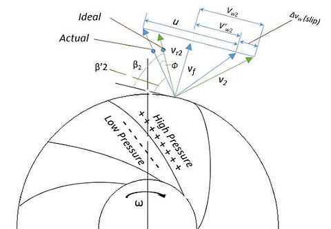 Mathematically, Slip factor denoted by 'σ' is defined as the ratio of the actual & ideal values of the whirl velocity components at the exit of impeller. The ideal values can be calculated using analytical approach while the actual values should be observed experimentally.
The Slip Velocity is given as:
VS = Vw2 - V'w2 = Vw2(1-σ)
The Whirl Velocity is given as:
V'w2 = σ Vw2


")
A simple explanation for the fluid slip can be given as :Consider an impeller with z number of blades rotating at angular velocity ω. A difference in pressure and velocity during the course of clockwise flow through the impeller passage can be observed between the trailing and leading faces of the impeller blades. High pressure and low velocity is observed at the leading face of impellers blade as compared to lower pressure with high velocity at the trailing face of the blade. This results in a circulation in the direction of ω around the impeller blade which prevents the air from acquiring the whirl velocity equivalent to impeller speed with non-uniform velocity distribution at any radius.
This phenomenon reduces the output whirl velocity, which is a measure of the net power output from a turbine or a compressor. Hence, the slip factor accommodates for a slip loss which affects the net power developed which increases with increasing flow-rate.
Factors accounting for slip factor
- Relative eddy.
- Back eddy.
- Impeller design or geometry
- Mean blade loading.
- Thickness of blade.
- Finite number of blades.
- Fluid entry conditions.
- Working fluid's viscosity.
- Effect of boundary layer growth.
- Flow separation.
- Friction forces on the walls of flow packages.
- Boundary layer blockage.
Mathematical Formulae for Slip factor

Fig 1. Ideal and Actual velocity triangles at impeller exit

- V'w2 : Actual Whirl Velocity Component ,
- Vw2 : Ideal Whirl Velocity Component
The Slip Velocity is given as:
VS = Vw2 - V'w2 = Vw2(1-σ)
The Whirl Velocity is given as:
V'w2 = σ Vw2
Slip Factor correlations[edit]
- Stodola's Equation: According to Stodola, it is the relative eddy that fills the entire exit session of the impeller passage. For a given flow geometry, the slip factor increases with the increase in the number of impeller blades, thus, accounts for one of the important parameter for losses.

- where, z = number of blades and

- For Radial tip, β2 = 900 ∴

- Theoretically, In order to get the perfect ideal flow guidance, one can infinitesimally increase the number of thin vanes so that the flow should leave the impeller at an exact vane angle.
- However, later experiments proved that beyond a particular value, further increase in number of blades results in reduction of slip factor due to increase in blockage area.
- Stanitz's Equation: Stanitz found the slip velocity does not depend upon of the blade exit angle and hence, gave the following equation.

- where, z = number of blades,
- β2 varies from 450 to 900.
- For radial tip: β2 = 900 ∴

- Balje's formula: An approximate formula given by Balje for radial-tipped (β2=900) blade impellers:
![\sigma =[1+{\frac {6.2}{z.n^{{2/3}}}}]^{{-1}}](https://wikimedia.org/api/rest_v1/media/math/render/svg/efdd8045dc0fb9445f8be8c60987ee339a32571a)
- where, z = number of blades , n =


FOB Price: US $2 / Piece
Min. Order: 100 Pieces
Min. Order: 100 Pieces
FOB Price: US $2 / Piece
Min. Order: 100 Pieces
Min. Order: 100 Pieces
FOB Price: US $52.3 / Piece
Min. Order: 100 Meters
Min. Order: 100 Meters
FOB Price: US $4 / Piece
Min. Order: 100 Pieces
Min. Order: 100 Pieces

FOB Price: US $1 / Piece
Min. Order: 100 Pieces
Min. Order: 100 Pieces
FOB Price: US $2 / Piece
Min. Order: 100 Pieces
Min. Order: 100 Pieces
FOB Price: US $2 / Piece
Min. Order: 100 Pieces
Min. Order: 100 Pieces
FOB Price: US $4 / Piece
Min. Order: 100 Pieces
Min. Order: 100 Pieces
FOB Price: US $3 / Piece
Min. Order: 100 Pieces
Min. Order: 100 Pieces
FOB Price: US $4 / Piece
Min. Order: 100 Pieces
Min. Order: 100 Pieces

FOB Price: US $1.81-2.42 / Piece
Min. Order: 100 Pieces
Min. Order: 100 Pieces
FOB Price: US $1.46-2.35 / Piece
Min. Order: 200 Pieces
Min. Order: 200 Pieces
FOB Price: US $2.58-3.44 / Piece
Min. Order: 100 Pieces
Min. Order: 100 Pieces
FOB Price: US $0.88-1.25 / Meter
Min. Order: 100 Meters
Min. Order: 100 Meters
FOB Price: US $4 / Piece
Min. Order: 100 Pieces
Min. Order: 100 Pieces


Tidak ada komentar:
Posting Komentar