
Joints in the components of life are very important because a media that we form may require a complex form to connect it also intended for a sufficiently significant distance; this requires a joint component whose meaning is very important for every life medium, for example: to join wood and wood joints, using nails, nuts and glue on glass and plastic and metal all have different joint methods for different media even at we humans are also known as join, which is love that makes everything more beautiful and attractive. Joint use for life especially that is for the reliability of a system as well as being attractive and tasty seems to have added value and strengthens the media that we use to have endurance and longevity, so I reviewed the joint here because it has food and something important for the meaning of life for each the media that we use for our lives .
LOVE ( Line On Victory Endless )

Gen. Mac Tech Zone JOINT ( Jump On In Through )

WELCOME JOINT
A joiner is an artisan who builds things by joining pieces of wood, particularly lighter and more ornamental work than that done by a carpenter, including furniture and the "fittings" of a house, ship, etc. Joiners may work in a workshop, because the formation of various joints is made easier by the use of non-portable, powered machinery, or on job site. A joiner usually produces items such as interior and exterior doors, windows, stairs, tables, bookshelves, cabinets, furniture, etc. In shipbuilding a marine joiner may work with materials other than wood such as linoleum, fiberglass, hardware, and gaskets.
The terms joinery and joiner are used in the UK, and the main trade union for American carpenters still calls itself the United Brotherhood of Carpenters and Joiners of America.
In the UK, an apprentice of wood occupations could choose to study bench joinery or site carpentry and joinery. Bench joinery is the preparation, setting out, and manufacture of joinery components while site carpentry and joinery focus on the installation of the joinery components, and on the setting out and fabrication of timber elements used in construction
A. XO Woodworking joints
Joinery is a part of woodworking that involves joining together pieces of timber or lumber, to produce more complex items. Some wood joints employ fasteners, bindings, or adhesives, while others use only wood elements. The characteristics of wooden joints - strength, flexibility, toughness, appearance, etc. - derive from the properties of the materials involved and the purpose of the joint. Therefore, different joinery techniques are used to meet differing requirements. For example, the joinery used to construct a house can be different from that used to make puzzle toys, although some concepts overlap.

Types of woodworking joints

Traditional woodworking joints
| Joint | Image | Description |
|---|---|---|
| Butt joint | The end of a piece of wood is butted against another piece of wood. This is the simplest and weakest joint. Of those, there is the a) T-butt, b) end-to-end butt, c) T-lap d) Miter butt and e) edge-to-edge butt. | |
| Lap joint | The end of a piece of wood is laid over and connected to another piece of wood. This is the next simplest and weakest joint. | |
| Bridle joint | Also known as open tenon, open mortise and tenon, or tongue and fork joints, this joint is where the through mortise is open on one side and forms a fork shape. The mate has a through tenon or necked joint. Bridle joints are commonly used to join rafter tops, also used in scarf joints and sometimes sill corner joints in timber framing. | |
| Dowel joint | The end of a piece of wood is butted against another piece of wood. This is reinforced with dowel pins. This joint is quick to make with production line machinery and so is a very common joint in factory-made furniture. | |
| Mitre joint | Similar to a butt joint, but both pieces have been bevelled (usually at a 45 degree angle). | |
| Finger joint | Also known as a box joint, is a corner joint with interlocking fingers. Receives pressure from two directions. | |
| Dovetail joint | A form of box joint where the fingers are locked together by diagonal cuts. More secure than a finger joint.[1] | |
| Dado joint | Also called a housing joint or trench joint, a slot is cut across the grain in one piece for another piece to set into; shelves on a bookshelf having slots cut into the sides of the shelf, for example. | |
| Groove joint | Like the dado joint, except that the slot is cut with the grain. | |
| Tongue and groove | Each piece has a groove cut all along one edge, and a thin, deep ridge (the tongue) on the opposite edge. If the tongue is unattached, it is considered a spline joint. | |
| Mortise and tenon | A stub (the tenon) will fit tightly into a hole cut for it (the mortise). This is a hallmark of Mission Style furniture, and also the traditional method of jointing frame and panel members in doors, windows, and cabinets. This joint is a good strong joint to use. | |
| Birdsmouth joint | Also called a bird's beak cut, this joint used in roof construction. A V-shaped cut in the rafter connects the rafter to the wall-plate.[2] | |
| Cross Lap | A joint in which the two members are joined by removing material from each at the point of intersection so that they overlap. | |
| Splice joint | A joint used to attach two members end to end. |


Nontraditional woodworking joints
| Joint | Image | Description |
|---|---|---|
| Pocket-hole joinery | A hidden screw is driven into the joint at an angle. | |
| biscuit | A wooden oval is glued into two crescent-shaped holes. | |
| Floating tenon joint | See Mortise and tenon | |
| stitch and glue | Wood panels stitched together, usually with copper wire, and glued together with epoxy resin. |


Traditional ways of improving joints

- Dowel: A small rod is used internal to a joint both to help align and to strengthen the joint. Traditional joints are used with natural timbers as they do not need any other materials other than the timber itself. for example: Butt joints. Dowel joints are also useful for pegging together weaker, cheaper composite materials such as laminate-faced chipboard, and where limited woodworking tools are available (since only simple drilled holes are needed to take the dowels).
Nontraditional ways of improving joints
- Biscuit joints: A small 'biscuit' is used to help align an edge or butt joint when gluing.
- Domino joiner: A trademarked tool similar to a biscuit joiner, where a piece larger than a biscuit has some of the advantages of dowels, and some of the advantages of biscuits.
Properties of wood
Many wood joinery techniques either depend upon or compensate for the fact that wood is anisotropic: its material properties are different along different dimensions.
This must be taken into account when joining wood parts together, otherwise the joint is destined to fail. Gluing boards with the grain running perpendicular to each other is often the reason for split boards, or broken joints. Furniture from the 18th century, while made by master craftsmen, did not take this into account. The result is this masterful work suffers from broken bracket feet, which was often attached with a glue block which ran perpendicular to the base pieces. The glue blocks were fastened with both glue and nails, resulting in unequal expansion and contraction between the pieces. This was also the cause of splitting of wide boards, which were commonly used during that period.
In modern woodworking it is even more critical, as heating and air conditioning cause major changes in the moisture content of the wood. All woodworking joints must take these changes into account, and allow for the resulting movement.
Strength
Wood is stronger when stressed along the grain (longitudinally) than it is when stressed across the grain (radially and tangentially). Wood is a natural composite material; parallel strands of cellulose fibers are held together by a lignin binder. These long chains of fibers make the wood exceptionally strong by resisting stress and spreading the load over the length of the board. Furthermore, cellulose is tougher than lignin, a fact demonstrated by the relative ease with which wood can be split along the grain compared to across it.
Different species of wood have different strength levels, and the exact strength may vary from sample to sample.
Dimensional stability
Timber expands and contracts in response to humidity, usually much less so longitudinally than in the radial and tangential directions. As tracheophytes, trees have lignified tissues which transport resources such as water, minerals and photosynthetic products up and down the plant. While lumber from a harvested tree is no longer alive, these tissues still absorb and expel water causing swelling and shrinkage of the wood in kind with change in humidity.[4] When the dimensional stability of the wood is paramount, quarter-sawn or rift-sawn lumber is preferred because its grain pattern is consistent and thus reacts less to humidity.
Materials used for joining


- Joints can be designed to hold without the use of glue or fasteners; a pinned mortise and tenon is an example of this.
- Glue is highly effective for joining timber when both surfaces of the joint are edge grain. A properly glued joint may be as strong or stronger than a single piece of wood. However, glue is notably less effective on end-grain surfaces. Animal glue is soluble in water, producing joints that can be disassembled using steam to soften the glue.
- Various mechanical fasteners may be used, the simplest being nails and screws. Glue and fasteners can be used together.
Traditional joinery
Many traditional wood joinery techniques use the distinctive material properties of wood, often without resorting to mechanical fasteners or adhesives. While every culture in which pieces of wood are joined together to make furniture or structures has a joinery tradition, wood joinery techniques have been especially well documented and is celebrated in the Indian, Chinese, European, and Japanese traditions. Because of the physical existence of Indian and Egyptian examples, we know that furniture from the first several dynasties show the use of complex joints, like the Dovetail, over 5,000 years ago. This tradition continued to other later Western styles. The 18th century writer Diderot included over 90 detailed illustrations of wood joints in his comprehensive encyclopedia.[5] While Western techniques focused on concealment of joinery, the Eastern societies, though later, did not attempt to "hide" their joints. The Japanese and Chinese traditions in particular required the use of hundreds of types of joints. The reason was that nails and glues used did not stand up well to the vastly fluctuating temperatures and humid weather conditions in most of Central and South-East Asia.[6] As well, the highly resinous woods used in traditional Chinese furniture do not glue well, even if they are cleaned with solvents and attached using modern glues.
Nontraditional joinery
Methods that are not considered traditional joinery have come about in modern times, largely to attempt to simplify the job of the woodworker for various reasons. These include biscuit joints and pocket hole joinery.


May 23, 2006 September 14, 2007 (3 months before completion)


B. XO Joining Plastic
There are several techniques for joining plastic parts. Equipment cost and labor for each method vary considerably. Most techniques have limits on the sizes and types of plastic that can be joined.
Mechanical fastening: The simplest way to join plastic parts is to design a fastening element (hinge, latch, detent) into the parts. Only stronger plastics are suitable for this method since the joint must survive the strain of assembly, service load, and possible repeated use. This form of fastening is suitable only for lightly loaded, nonrigid assemblies where precision is not critical.
Mechanical fasteners (screws, rivets, pins, sheet-metal nuts) are the most common joining method. They require a plastic that can withstand the strain of fastener insertion and subsequent high stress around the fastener. Conventional machine screws are rarely used except with extremely strong plastic.
There are a number of fasteners designed for use with plastics. Threaded fasteners work best on thick sections. Thread-forming screws are preferred for softer materials, while thread-cutting screws work best on harder plastics. Push-on locknuts and clips may be better for thinner sections. If a fastener has to be removed a number of times, metal inserts are recommended. They may be molded in place, forced, glued or expanded into holes, or inserted ultrasonically.
Fusion bonding: Plastic parts too complex or large to be fabricated on available molding equipment are sometimes made as subcomponents and welded together by fusion bonding. Holding fixtures ensure accurate mating and alignment of the parts to be joined.
To plasticize the part edges, the fixtures press the parts against a heating platen. As the platen melts the part surface, the plastic material is displaced while the fixture maintains part pressure against the platen. This initial fusing produces a smooth surface by removing surface imperfections, warps, or small sinks. Melted material continues to be displaced until "melt stops" on the platen contact the holding fixtures. Material is then no longer displaced and the parts are held against the platen until each part edge is plasticized to a predetermined depth. Melt depth is regulated by contact time, which is usually from 3 to 6 sec.
After part edges are plasticized, the fixtures open and the platen is withdrawn. The fixtures then reclose, forcing the parts together until "seal stops" on the fixtures come into contact. The parts are held together under pressure as the melted material cools, bonding them together.
Usually, fusion bonding joins thermoplastics such as polyethylene, polypropylene, and ABS. However, with slight changes, the process can be used to join both filled and unfilled nylon.
To fuse unfilled nylon, a thin, nickel-chrome blade, rather than a platen, is heated to about 1,100°F. The heated blade is brought to within 0.0005 in. of the material in a brief heating cycle. The blade is then removed and the part conventionally fixtured. Glass-filled nylon can be softened using direct heat, if care is taken to clean the blade or platen with a steel brush between each cycle.
Cooling time normally is the same as melt time -- from 3 to 6 sec. When cooling is complete, the gripping mechanism in one of the holding fixtures releases the part, the fixtures open and the finished part is removed manually or automatically. Total machine time from start to finish is generally about 15 sec, well within the range of the injection-molding systems often used in conjunction with fusion bonding.
Hot-gas welding: This is a low-speed process for fabricating large structural parts from sheet stock. A thermoplastic rod is heated with the parts to be joined until they soften and can be pushed together. The heat source is usually an inert gas. Top speed on long, straight welds is about 40 in./min. Intricate parts require more time. Operator skill is critical for both weld strength and appearance.
Vibration welding: Vibration welding produces pressure-tight joints in circular, rectangular, or irregularly shaped parts made from almost any thermoplastic material -- even in dissimilar materials having a melt-temperature spread as great as 100°F. The process is particularly suited for hollow, container-type components having the weld joint in a single plane.
The parts are frictionally heated by pressing them together and vibrating one of the parts at 120 to 240 Hz, in the plane of the joint.
After 2 to 3 sec, vibration is stopped at the exact required relative position of the two pieces. Pressure is maintained briefly while the softened plastic cools. Joint strength is very near that of the parent material. Cycle time, including manual loading and unloading, ranges between 5 and 8 sec for most parts. The process is adaptable to fully automated systems.
Vibration welding accommodates large parts that are impossible or impractical to weld by other methods. Parts can be rectangular or irregular, as long as the weld joint is in a single plane and a small amount of motion (at least 0.12 in.) in that plane is possible. Components with weld surfaces as long as 20 in. have been successfully joined.
Solvent bonding: Plastics are softened by coating them with a solvent, then clamped or pressed together. The plastic molecules mix together, and the parts bond when the solvent evaporates. This process is limited to thermoplastics. Fusion time is a function of the solvent's evaporation rate and may be shortened by heating.
Pure solvents provide the simplest, lowest-cost bond. Doped solvents, which cost more, contain solutions of the plastic being bonded to fill gaps in imperfectly fitting parts. Next in complexity and cost come monomer and polymerizing solvents. These materials contain catalysts and promoters added to doped solvents to produce polymerization at room temperature or a temperature below the softening point of the thermoplastic.
Solvent-bonded parts must be pressed together for 10 to 30 sec before the joined parts can be handled. Pressure is critical, as too much pressure causes parts to distort. A day or more at room temperature or several hours at elevated temperature may be needed to cure the bond.
Ultrasonic welding: Pulses are transmitted to the part by a resonant vibrating tool called a horn, causing two plastic materials to vibrate against each other. Vibration heats and fuses the parts together. Plastic products including blends or alloys of different resin families can be joined by ultrasonic welding. Such dissimilar parts should be designed carefully, and both the resin and equipment suppliers should become involved early to ensure that ultrasonic techniques can produce a suitable bond.
Ultrasonic assembly is often done at 20 kHz to achieve the vibrational amplitude and power needed to melt thermoplastics. However, higher frequencies that produce less vibration can also join thermoplastics, especially engineering thermoplastics such as reinforced polymers. For some applications, use of 40 kHz means less material degradation. Tooling used for 40-kHz welding is smaller than that used for 20 kHz; therefore, the welds produced at 40 kHz are generally smaller.
Pressure is critical. Too much causes the parts to vibrate as an integral structure with no heating. Too little does not provide enough contact friction or heating.
Ultrasonic welding is fast. Assembly rates of more than 25 parts/min are possible with a single station. There are no secondary operations, such as coating, inserting, or cleaning. The process requires fairly rigid materials. Dissimilar-material sonic welds can be made, but the melting temperatures of both materials must be quite close, otherwise only the lower-melting material will soften and a bond will not form.
Ultrasonics can also be used to insert metal components into plastic, stake metal and plastic parts together, or spot-weld plastic sections.
Induction welding: Induction welding can be done by pressing two pieces of plastic material together around a metal insert. When passed through a magnetic field, the encased metal is heated, and the compression produces a fusion weld. The metal remains sealed inside the part.
Thermoplastic bonding agents filled with either electromagnetic or ferrite materials may also be used in induction welding. The material, in the form of a preformed ring or strip, or as a hot melt, for instance, is inserted between the mating parts before induction heating. If metallic particles are used, the alternating magnetic field induces current flow within the particles, generating heat. When ferrite is used, no current is produced. Instead, heat is produced by molecular friction as the particles try to retain their magnetic charge when the fields are reversed.
To eliminate the need to add metal to the joint, metal powder can be added to the original plastic molding, but a much higher frequency is needed.
Induction welding is a high-cost technique and is suitable for difficult-to-weld plastics such as polypropylene, and for shapes that cannot be fitted into an ultrasonic welding machine. The process is best suited for bonding most polypropylene, polyethylene, styrene, ABS, polyester and nylon in high-volume, highly automated joining operations.
Heat-resistant polypropylenes that cannot be joined with adhesives or other welding techniques may be successfully joined using induction welding. Bonding agents heated inductively reach temperatures of 300°F in 0.1 sec to fuse with the heat-resistant substances.
Dielectric welding: Dielectric welding is used on films and thin sheets up to about 60 mil, primarily in packaging. The technique uses the breakdown of plastic under high voltages and frequencies (13 to 120 MHz) to produce dielectric heating and fuse the plastic. Welding speed is a function of dielectric-loss factor, material thickness, and the area subjected to the voltage. Dielectric welding is ideal for PVC materials.
C .XO JOINT MIRROR EX. Understanding Snapshots


Background
Snapshot is a method where in a point in time instant copy (by definition read-only) can be created for the unit of data. It has been into existence for a very long time however techniques to create snapshots have evolved over a period of time and its getting more popular recently because of its adaptability in to wide variety of applications and faster turn around time. Lets take a look at some of those techniques and try to understand how they work. We will look at some of the recent developments and see where this technology is leading to.
Snapshot is a method where in a point in time instant copy (by definition read-only) can be created for the unit of data. It has been into existence for a very long time however techniques to create snapshots have evolved over a period of time and its getting more popular recently because of its adaptability in to wide variety of applications and faster turn around time. Lets take a look at some of those techniques and try to understand how they work. We will look at some of the recent developments and see where this technology is leading to.
Snapshot Technologies There have been many implementations of the Snapshot technology and they vary depending on the use cases and the way users want to visualize them. Both File Storage (NAS) and Block Storage (SAN) offer this as one of the primary features now a days.
At a broad level there are two categories of snapshots that we can be visualized by users, implementation techniques may vary.
- Space Efficient Snapshots
- Full Copy Snapshots
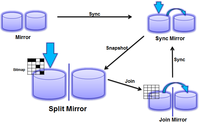
Here is how this technique works. There is a preparation required prior to creating snapshot, i.e. creation of mirror unit (volume, in case of block storage). Mirror copy keeps up to date with the changes happening on the original volume. When snapshot request is made, mirror relationship simply stops and changes stop from being replicated. In other words mirror copy represents a snapshot of the original volume as of the point of snapshot creation. Snapshot can be dissolved (deleted) simply by joining the mirror relation back. To optimize the joining performance a bitmap is used to track changes which were made after the snapshot was created, as shown below:
Space Efficient SnapshotsIt is evident that Full Copy occupies a lot of space and is not feasible for scenarios where a number of snapshots (over 1024) is desired. Space Efficient Snapshots is the alternate technique which can be used to save space used in the snapshot volumes. Two common popular implementation of this techniques are known as:
- COW (Copy-On-Write)
- ROW (Redirect-On-Write)
Copy-On-Write Snapshot Copy On Write is an initial implementation of the space efficient snapshots and pretty commonly adapted by various storage vendors. Lets run through an illustration to learn this more in detail.
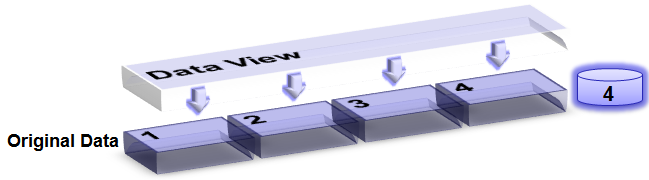
Lets Imagine we have a unit of data containing 4 blocks, consequently consuming 4 units of storage space. When viewed, contents are visible as values 1, 2, 3, and 4.
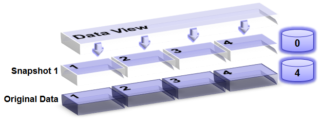
When a snapshot request is made, it leads to creation of virtual data unit containing all the pointers to the original data. This is viewed as snapshot 1 in the figure and occupies no space on the storage. When viewed, both snapshot and original contents can be viewed as 1, 2, 3 and 4. At this time all the data blocks are marked as COW to represent the fact that they are shared.
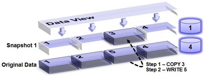
However, when the new write request is received for the COW block, a COPY is made before the the data block is written in to the block. The COPY (which represents data as of the snapshot time), now belongs to snapshot (increasing the occupied size to 1 block). When viewed, current data shows 1, 2, 5 (new) and 4. However, snapshot contents still show 1, 2, 3, 4.
At this time, if we create a new snapshot (snapshot 2) of the current data, then snapshot 2 contents will be same as current data with no space occupied for snapshot 2, i.e. 1, 2, 5, 4. Snapshot 1 view continues to be same as it was at time snapshot 1 was created, i.e. 1, 2, 3, 4.

A new write request would end up creating a COPY of block 2 to snapshot 2 making its usage count to 1 block.

Redirect-On-Write SnapshotAs see above, COW technique includes a COPY operation each time a block is written to COW block. Under heavy workload with too many snapshots this can pose significant performance issues. ROW technique solves this problem, i.e. it avoids copy and redirects write to new block as its name suggests. Lets look at an illustration of how this works (Actually implementation may vary little depending on the constraint on the storage volumes, storage pools, etc).
Lets take the similar situation where there a 4 blocks and the original view of data (with no snapshots) looks like as shown.

When we create a 1st snapshot, it looks pretty much similar to the snapshot was taken in case of COW snapshot technique with a different that original contents can be visualized to contain pointers to data blocks, leading to the total block count unchanged.

However, when a write request is made, writes are just redirected to new blocks instead of creating any COPY of existing blocks on disk. At this time current data view is reflected to include new block, i.e. 1, 2, 5 and 4, which snapshot contents remain to 1, 2, 3 and 4.

Next snapshot request follows the same process leading to the view shown in the figure.

Finally, a new write request is redirected to a new block which belongs only to the current data view, eliminating the need to perform COPY and still being able to optimize the storage space.

Lets take the similar situation where there a 4 blocks and the original view of data (with no snapshots) looks like as shown.
When we create a 1st snapshot, it looks pretty much similar to the snapshot was taken in case of COW snapshot technique with a different that original contents can be visualized to contain pointers to data blocks, leading to the total block count unchanged.
However, when a write request is made, writes are just redirected to new blocks instead of creating any COPY of existing blocks on disk. At this time current data view is reflected to include new block, i.e. 1, 2, 5 and 4, which snapshot contents remain to 1, 2, 3 and 4.
Next snapshot request follows the same process leading to the view shown in the figure.
Finally, a new write request is redirected to a new block which belongs only to the current data view, eliminating the need to perform COPY and still being able to optimize the storage space.

Conclusion
Snapshots as per the original definition has been Read-only as it was meant to capture point-in-time instance of the data. However new technologies and use cases have mandated to use snapshot copy as read-write unit, which originally forks as a point-in-time copy and later is changed to delink from the parent as an independent copy / clone.
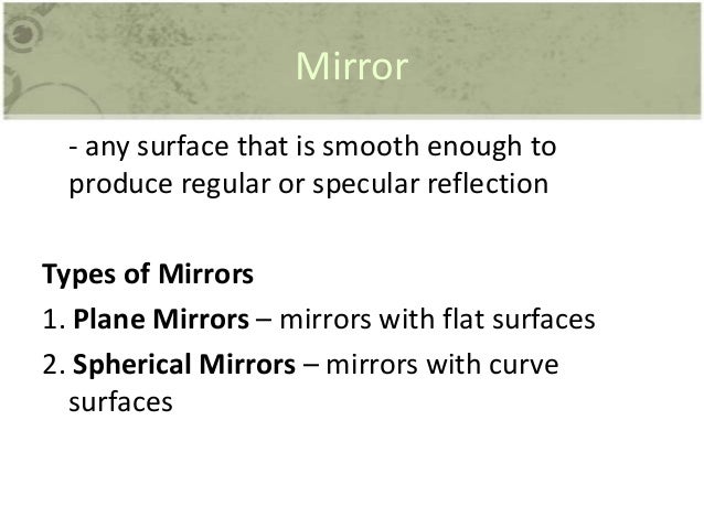
Ray Optics
What is ray optics?
Light is a wave and although it spreads as it moves farther from its source, it can be approximated as a straight line. We can thus assume light as a ray, that is a straight path on which light moves in a homogeneous medium, the study of light (as a ray) is termed as ray optics.
Light and its reflection
Reflection is the process through which light ray bounces back to the same medium of its source, on interacting with the boundary (which can be hard or an interface of 2 mediums). Ray optics gives us certain rules to predict this reflectional behavior of light. The angle between the normal at the incidence point and the incident ray is called the angle of incidence. The angle between the normal at the incidence point and the reflected ray is called the angle of reflection. These laws remain the same on curved or plane surfaces.
The angle of incidence is equal to the angle of reflection. (i=r) – This is one of the laws of ray optics.
The angle of incidence is equal to the angle of reflection. (i=r) – This is one of the laws of ray optics.
What is deviation?
Deviation is the angle between the direction after reflection and direction before it. So if the angle of incidence is i, then the deviation is 180-2i (since i=r).
What happens when a ray of light is reflected from a plane surface?
If a surface is rotated by x degrees in clockwise direction while keeping the incident ray fixed, then the reflected ray rotates by 2x in the same way, that is clockwise.

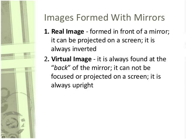
What happens when a ray of light is reflected from a plane mirror?
On placing an object in front of a mirror, the image is visible behind the mirror. Here, distance between object and mirror = distance between mirror and image. The characteristic of this image is that it is erect, laterally inverted and virtual. The images of the object and the object itself will always lie on the circumference of a circle with center at the intersection point of 2 inclined mirrors.
In case of a mirror, when the object in front of it moves at the speed u, towards or away from the mirror, then the image moves at the same speed towards the same direction. However, the relative speed becomes 2u. When mirror moves towards the object at u speed, the image will move at 2u speed.
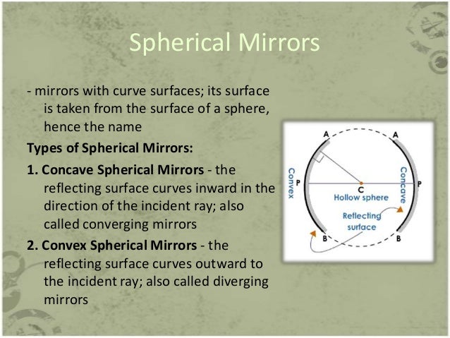
Explain what happens when a ray of light is reflected from spherical mirrors
On a spherical mirror, one surface is silvered while the other is the reflecting surface. A mirror is called concave when the convex side is silvered while the other side acts as a reflecting surface. A mirror is called convex mirror when the concave side is silvered while the other side acts as a reflecting surface. The center of the sphere is known as the center of curvature. The radius of the sphere is known as the radius of curvature. The geometric center of the mirror is a pole. The line passing through the pole and center of curvature is the principle axis and a line segment joining the mirror to its center of curvature is normal.

Paraxial rays are close to the principal axis and make small angles with it such that they are almost parallel to it.
The following diagrams can explain the images formed by the spherical mirrors:

In short, the following table summarizes the characteristics of the image formed by both the concave and convex mirrors.

The rules for obtaining images in case of spherical mirrors are
- The ray parallel to the principal axis passes through the mirror’s focus after its reflection from the mirror
- A ray passing through the center of curvature retraces its path back.
- A ray passing through a concave mirror’s principle focus or directed towards convex mirror’s principle focus, becomes parallel to principle axis post reflection.
- A ray that is oblique to the principle axis, towards the pole of the mirror, is obliquely reflected. Here too, the law of reflection is followed.
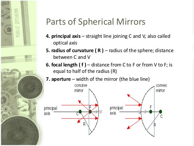
What is the relation between F and R?
In each case, F (focal length) of a concave mirror is equal to half of R (Radius of curvature) of the mirror.
In each case, F (focal length) of a concave mirror is equal to half of R (Radius of curvature) of the mirror.
Magnification formula
The magnification produced by mirror can be written by the following formula:
Magnification = height of the image / height of the object.
What is refraction of light?
When a ray is incident on two transparent media’s boundary, a fraction of it moves into the second medium with a slight change in the direction. This process is called refraction. The refractive index is defined as the ratio between the speed of light in vacuum to that in the medium.
Refractive index= c/v where c is speed in vacuum and v is speed in medium.

What are thin lenses and how are images formed?
it is a portion of any transparent refracting medium which is bounded by 2 surfaces. However, one of the 2 must be curved. The different kinds of lenses are noted in the diagram
it is a portion of any transparent refracting medium which is bounded by 2 surfaces. However, one of the 2 must be curved. The different kinds of lenses are noted in the diagram
The center of the sphere which contains the two lenses is called the centers, the radius of it is called the radius of curvature, the line joining the 2 centers is called the principle axis, the point on this axis through which the ray passes undeviated is called optical center, and the distance between the optical center and the second principal focus is focal length.
What is a prism?
It is a structure with 2 plane surfaces that are inclined to each other. The following diagram explains the various components of a prism.
An incident ray that enters a prism deviates due to refraction that occurs twice when the medium changes. Hence it happens once at the boundary separating air and glass and next to the one separating glass and air.
Fiber Optic Splicing

Fiber optic splicing is an important method of joining two fiber optic cables together. It is a preferred solution when an available fiber cable is not sufficiently long for the required run. Besides, fiber optic splicing is designed to restore fiber optic cables. In case they are accidentally broken. Nowadays, fiber optic splicing is widely deployed in telecommunications, LAN (Local Area Network) and networking projects. Typically, we can undertaken fiber optic splices two ways: fusion splices and mechanical splices. This paper firstly illustrates the specific process of fusion splicing method and mechanical splicing method. And then makes a comparison of the two methods for your reference.
Fiber Optic Splicing: Fusion Splicing Method
Fusion splicing is a permanent connection of two or more optical fibers. The two fibers are welded together with an electronic arc. This is the most widely used method of fiber optic splicing. Because it provides the lowest loss, less reflectance, strongest and most reliable joint between two fibers. When you adopt this method, fusion splicing machines are often used. Generally, there are four basic steps in the fusion splicing process. They are illustrated in following one by one.

Step 1: strip the fiber
The splicing process begins with the preparation for both fibers ends to be fused. So you need to strip all protective coating, jackets, tubes, strength members and so on. And you just leave the bare fiber showing. It is noted that the cables should be clean.
Step 2: cleave the fiber
A good fiber cleaver is crucial to a successful fusion splice. The cleaver merely nicks the fiber and then pulls or flexes it. So to cause a clean break rather than cut the fiber. The cleave end-face should be perfectly flat and perpendicular to the axis for a proper splice.
Step 3: fuse the fiber
When you fuse the fiber, there are two important steps: aligning and melting. Firstly, you need to align the ends of the fiber within the fiber optic splicer. After proper alignment, you need to utilize an electrical arc to melt the fibers. So you can permanently weld the two fiber ends together.
Step 4: protect the fiber
A typical fusion splice has a tensile strength between 0.5 and 1.5 lbs. And it is not easy to break during normal handling. However, it still requires protection from excessive bending and pulling forces. By using heat shrink tubing, silicone gel and mechanical crimp protectors can keep the splice from outside elements and breakage.
Fiber Optic Splicing: Mechanical Splicing Method
If you want to make splices quickly and easily, the mechanical splice is a better choice. A mechanical splice is a junction of two or more optical fibers. The fibers are aligned and held in place by a self-contained assembly. A typical example of this method is the use of connectors to link fibers. This method is most popular for fast, temporary restoration and splicing multimode fibers. The fibers are in a premises installation. Like fusion splice, there are also four basic steps in a mechanical splice.

Step 1: strip the fiber
Fiber preparation is practically the same as that of fusion splicing. Just remove the protective coatings, jackets, tubes, and strength members. So we can see the bare fiber. Then ensure the cleanliness of the fiber.
Step 2: cleave the fiber
The process is the same as the cleaving of fusion splicing. It is necessary to obtain a cut on the fiber exactly at right angles to the axis.
Step 3: mechanically join the fiber
In this step, we don’t use heating as infusion splice. We simply connect the fiber ends together inside the mechanical splice unit. The index matching gel inside the mechanical splice apparatus is helpful. Because it can couple the light from one fiber end to another.
Step 4: protect the fiber
Once fibers are spliced, we place them in a splice tray and then in a splice closure. Outside plant closures don’t need to use heat. We carefully seal shrink tubing to prevent moisture damage from the splices.
Which Method is Better?
Both fusion splicing and mechanical splicing method have their advantages and disadvantages. We need to Choose fusion splice or mechanical splice depends on the applications.
The fusion splicing provides a lower level of loss and a higher degree of permanence than mechanical splicing. However, this method needs to use expensive fusion splicing equipment. In view of this, we tend to use fusion splice for the long and high data rate lines. These rate lines are unlikely to be changed once installed.
The mechanical splicing is often used in these situations. When splices need to be made very quickly and the expensive equipment for fusion splices are not available. Some mechanical fiber optic splice allows both connection and disconnection. So a mechanical splice can be used in not permanent situations.
Conclusion
Fiber optic splicing is an important method in the installation of fiber optic networks. We need to Choose fusion splice or mechanical splice depends on the applications. When you do fiber splicing, you need to follow the specific instructions strictly for perfect splices. Besides, keeping all splicing tools clean is also important.
As fiber deployment has become mainstream, splicing has naturally crossed from the outside plant (OSP) world into the enterprise and even the data center environment. Fusion splicing involves the use of localized heat to melt together or fuse the ends of two optical fibers. The preparation process involves removing the protective coating from each fiber, precise cleaving, and inspection of the fiber end-faces. Fusion splicing has been around for several decades, and it’s a trusted method for permanently fusing together the ends of two optical fibers to realize a specific length or to repair a broken fiber link. Then how to do fusion splicing? You may need a fiber optic splicing machine called fusion splicer.
What Is Fusion Splicer?
Fusion splicer may be the act of joining two optical fibers end-to-end using heat. The thing is to fuse both the fibers together in such a way that light passing with the fibers is not scattered or reflected back from the splice, and thus the splice as well as the region surrounding it are almost as strong because virgin fiber itself. The basic fusion splicer apparatus includes two fixtures which the fibers are mounted and two electrodes. Inspection microscope assists in the placement in the prepared fiber ends into a fusion-splicing apparatus. The fibers they fit in to the apparatus, aligned, and then fused together.

Initially, fusion splicing used nichrome wire as the heating unit to melt or fuse fibers together. New fusion-splicing techniques have replaced the nichrome wire with fractional co2 lasers, electric arcs, or gas flames to heat the fiber ends, causing them to fuse together. The little size of the fusion splice along with the development of automated fusion-splicing machines make electric arc fusion the most popular splicing approaches to commercial applications.
Fusion Splicing vs Mechanical Splicing
There are two types of optic fiber splicing. One is fusion splicing we mentioned above, another is mechanical splicing (shown in the figure below). In mechanical splicing two fiber optic cables are held end to end inside a sleeve using some mechanical mechanism. In this type of technique fibers aren’t joined permanently rather just accurately hold together, so that light can easily pass through from one end to another, while in fusion splicing two fibers are fused or wielded together using an electric arc, fusion splicing is most widely used technique because it provides a reliable join with lower insertions loss and practically no back reflection. Fusion splicing is generally applied on single mode fibers but in some special cases it can also be used for multi mode fibers.

Fusion Splicing Steps Introduction
Splicing fiber optic cable ends together is often a precise process with hardly any room for error. This is because the optical fiber ends must be gathered absolutely perfectly to be able to minimize potential optical loss or light leakage. Properly splicing the cable ends demands the usage of a high-tech tool called a fusion splicer. A fusion splicer perfectly mates the optical fiber ends by melting or fusing them to the other. Splicing fiber cables surpasses using connectors considering that the fusing process results in a superior connection that features a lower level of optical loss. When performing a fusion splice there are generally five different steps:
1. Stripping the fiber
To start fusing your fibers together, you must remove or strip the protective polymer coating around the optical fiber. This is usually done with a mechanical stripping device, similar to a pair of wire strippers. Remember to clean the stripping tools before you start the fusing process.
2. Cleaning the fiber
After the fiber has been stripped of the coating, it’s time to clean the bare fiber. Using a 99.9% isopropyl alcohol (IPA) and lint-free wipes will keep the glass free of any contaminations.
3. Cleaving the fiber
A good cleaver is crucial to a successful fusion splice. The cleaver nicks the fiber and pulls or flexes it to cause a clean break rather then cut the fiber, which makes the end-face flat and perpendicular to the axis of the fiber.
4. Fusing the fiber
After the fibers have been cleaved, fuse them together with a fusion splicer. First, you must align the ends of the fiber within the splicer. Once properly aligned, melt the fibers with an electric arc, permanently welding the ends together.
5. Protecting the fiber
After the fibers have been successfully fused together, the bare fiber is protected either by re-applying a coating or by using a splice protector.
Conclusion
Fusion splicing provides permanent low-loss connections that are performed quickly and easily, which are definite advantages over competing technologies
D. XO Electronics Primer: Solder Electronic Components
- Soldering is a process in which two or more metal items are joined together by melting and then flowing a filler metal into the joint—the filler metal having a relatively low melting point.
- Soldering is used to form a permanent connection between electronic components.
- The metal to be soldered is heated with a soldering iron and then solder is melted into the connection.
- Only the solder melts, not the parts that are being soldered.
- Solder is a metallic "glue" that holds the parts together and forms a connection that allows electrical current to flow.
- You can use a solderless breadboard to make test circuits, but if you want your circuit to last for more than a few days, you will want to solder the components together.


Joint Terminal

What can iST


FLEX PCB - RIGID-FLEX PCB - FLEXIBLE CIRCUIT BOARD
 Enlarge |
|
Flexible PCBs are relied upon for their physical ability to contract & expand for specialized products. These types of thin PCBs are used in a variety of products, such as automotive instrument panels, computer disk drives, medical controls, and telecommunication systems.
EFFICIENT PCB FABRICATION

Efficient PCB Fabrication
Summary :
Too often the information en-route from PCB Design to PCB Fabrication is not conveyed properly, resulting in poor boards, higher costs, design re-spins, and ultimately slower product time-to-market. However, these problems can be avoided through careful planning, thorough communication, and proper documentation from the design-end.
Too often the information en-route from PCB Design to PCB Fabrication is not conveyed properly, resulting in poor boards, higher costs, design re-spins, and ultimately slower product time-to-market. However, these problems can be avoided through careful planning, thorough communication, and proper documentation from the design-end.
Too often the information en-route from PCB Design to PCB Fabrication is not conveyed properly, resulting in poor boards, higher costs, design re-spins, and ultimately slower product time-to-market. However, these problems can be avoided through careful planning, thorough communication, and proper documentation from the design-end.
A simple view of a typical product cycle from the Design Engineer to the Assembly stage is shown above.
At Electronic Interconnect, at the Prototype Fabrication stage, we have seen a plethora of issues which could have been avoided if the Design Engineer had only provided the correct documentation and data for manufacturing the PCB. Some of the main issues are highlighted in the red box above. Overall, going back to the Design Engineer for documents, such as a dimensional drawing of the PCB, result in loss of time and money for all parties involved. Major issues which cause slowdown at the Prototype stage occur after a design-for-manufacturing check finds errors which will impede moving forward due to technology constraints; this is to say when no such constraints were intentionally added by the Design Engineer. For example, small annular rings around Vias, exceptionally thin trace widths and spacings, or antennas and electrical shorts, missing layers, missing drawings and notes; these issues will halt all operations in the engineering department before going to the plant floor. This will, in-turn, mean that the Design Engineer will have to go through each of these issues and either provide waivers to continue as-is, or a new set of fixed data.
In conclusion, valuable time can be saved with a concentrated effort at the design stage to provide proper documentation and cleaner data for efficient PCB fabrication!
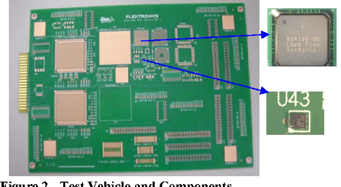
The solder joint metallurgy of mixed alloys was characterized and the lead distribution through the solder joint was analyzed, for different package types and under various process conditions. The results showed that the solder paste amount (ultimately the tin percentage, Sn% in the alloy) and the reflow temperature play critical roles in the mixed alloy assembly, both in terms of compositional homogeneity and voiding. The reliability of mixed alloy solder joints was then studied at various process conditions, under different thermal and mechanical stress environments. The study revealed that the sensitivity of the reliability of the mixed alloy solder joints to the process condition depends on the type of environmental loading.
Electronics/Soldering
Soldering is the use of a conductive substance with a low melting point (solder) to electrically connect components together. It is frequently used to join wires to leads of components such as switches or to join components of all kinds to a printed circuit board. The primary tool used for applying solder is a soldering iron, a device whose metal tip heats to temperatures well above the melting point of solder. This is used to melt the solder and allow it to flow into a joint.
Soldering is an acquired skill, and it takes practice to become adept. There are many tips, tricks and guidelines on how to produce good soldered joints, and this module aims to present them to you.
The first and most important rule of soldering is to choose your tools with care. Both the solder and the iron must be chosen to suit the application. The first two sections below deal with the different kinds of solder and iron and which to choose for what.
About solder
Solder is a metallic compound that has a low melting point, usually around 200°C. The composition of solder varies depending on the type, but usually contains lead or tin or both. The most common types are given below. It is available in wire, stick or pellet form. Sticks and pellets are for solder-pots; for normal soldering, you will need solder wire.
Solder wire is a very flexible, silvery coloured wire that is usually supplied on reels that are sized by weight. Common weights are 250 g, 500 g, 1 kg or 2 kg. It generally costs around £6 or $12 for a 500 g reel. It is very soft, and is easily cut by wire cutters and smaller diameters can be snapped by hand (though this is not recommended, as you will see below).
Gauge
Solder wire is available in widths given in "standard wire gauge" (SWG). The larger the SWG number, the thinner the wire. Common gauges are 18 and 22, although others are available.
18 gauge solder is suitable for soldering large components and thick wire, as a large quantity of solder can be delivered quickly. However, for smaller, more detailed work, 18 gauge is too thick. Soldering the pins of standard dual in-line packages (DIPs) is about as fine as 18 gauge solder can usefully go.
22 gauge solder is thinner than 18 gauge, and should be used for most electronics work, as it allows much greater control over the quantity of solder delivered, and the chances of accidentally bridging a gap due to over-application or the wire's width are greatly reduced.
Finer gauges such as 26 are available for very fine work with SMT (surface-mount) components.
60/40

60/40 solder is made of 60% tin and 40% lead. It has a melting point of around 190°C, depending on the exact composition. Iron tip temperatures of at least 300°C are recommended. It is also very soft, meaning that cracks do not form so readily if the joint moves during cooling.
63/37
63/37 solder is made of 63% tin and 37% lead. It has a melting point of 183°C, slightly lower than the more common 60/40 blend. The primary advantage of this solder is not the lower melting point, but its eutectic property. Non-eutectic solders, like the 60/40 solder, have a semi-solid state between solid and liquid. If a joint is moved during this stage, it can result in what is called a cold solder joint. Eutectic solders, like the 63/37, do not have this semi-solid state and are thus considered easier to work with as it produces fewer bad joints. However, these solders typically cost more than their non-eutectic counterparts.
50/50
This is made of a half and half mix of tin and lead. Never use 50/50 solder for electronics — it is meant for plumbing. (There are brands[Worthington 50/50 leaded #331887], which is used for electronics and specifically not intended for plumbing). Otherwise, you may end up with failed joints, as the 50/50 solder does not have the same properties as 60/40, having a higher melting point and lower ductility. Also, it is very unlikely to have flux included in it like rosin core solders.
Lead-free solder
Solder containing lead is slowly being phased out under new EU directives (especially the RoHS and WEEE directives) and being replaced with solders consisting of tin-antimony alloys. It will likely be many years before lead solder is supplanted for good, but even now many shops do not sell lead solder any more. Lead-free solder has a higher melting point than lead solder and uses more aggressive fluxes. This means that the soldering iron will have to be made for lead-free solder in order to supply the right temperature — it melts at around 230°C — and the iron bits need a different coating to withstand the flux. Using a soldering iron meant for lead solders may result in dry joints and shortened bit life.
Lead-free solder is generally about 20%-50% more expensive than lead solder.
There are many different alloys and their properties can be found in this Wikipedia article.
Flux and rosin core solder


Flux is a compound that is used to improve the quality of the soldered joint. It does this in three ways:
- It chemically removes oxidation from the surfaces being soldered.
- It prevents air from oxidising the surfaces once they have been cleaned.
- It increases the "wetting" of the surfaces when the solder is applied.
Wetting is the degree to which the solder flows across the surfaces being joined. Without flux, a dry joint may be formed, making a poor connection. See below for a description of dry joints.
Rosin core solder has channels inside filled with rosin flux. Because flux melts before the solder, the embedded flux automatically cleans the joint before the solder flows into it. Rosin core solder should always be used for electronics. Both lead and lead-free solder can be rosin core. Never use acid core solder for electronics — it is intended for plumbing and sheet metal work only, and the acid residue will corrode and ruin electrical joints. Acid flux remains chemically active at room temperature, while rosin flux becomes inert and harmless once the joint cools.
After soldering, a layer of flux may be seen around the joint. This is usually a burnt-looking brown layer (usually found when the joint has been overheated), or a shiny clear layer. This is not usually a problem, but you may want to remove it with a cotton bud soaked in methylated spirits or alcohol to produce a more professional appearance.
Flux is also available in "pen" applicators. This allows it to be applied, before soldering with rosin core solder, to surfaces that need to be very well fluxed such as SMT pads and unfluxed solder braid in order to be reliable.
About soldering irons
Soldering irons come in all shapes, sizes and power ratings. Most irons are made of a heating element attached to a handle, with interchangeable tips used to work on the joint.
Power rating and temperature control
The power rating governs how hot the iron gets and how quickly it heats up. A high power rating means that if a joint with a large thermal mass is being soldered, the bit will not cool down much. However, a high power rating used for fine work may overheat the joint, damaging the component or circuit board.
Generally, a rating of around 18 W is good for fine work, while a 25 W to 50 W rating is good for heavier electrical soldering, such as on mains lighting.
Inexpensive soldering irons have a fixed power consumption — they rely on the dissipation of heat into the surroundings to achieve thermal equilibrium at the desired temperature. These are sufficient for most hobby electronics work. A simple iron like this costs around £20 to £30 (US$30 to US$50).
For more advanced work, especially work involving very small components that overheat easily, a temperature-regulated or variable temperature soldering iron is needed. These usually are sold as a soldering station, comprising a soldering iron and a separate power supply. The station monitors the temperature at the soldering tip and adjusts the power output accordingly. Some stations use a magnetic switch that cycles the power on and off, using the Curie Effect; the soldering tips are designed to lose their ferromagnetic properties at a defined temperature, usually 370°C (700°F), 425°C (800°F) or 480°C (900°F), shutting off heater power until the tip cools and regains its magnetic properties. Tip temperature in such irons may fluctuate in a 4°C (25°F) range. Such stations are frequently used in manufacturing environments. For laboratory use, stations are available with a thermistor at the tip to monitor temperature and the temperature can be continuously varied by a rotary control. Tip temperature may also be displayed by an LED readout on the base unit. More expensive stations have an hot air pencil for desoldering purposes, as well. You can expect to pay up to £500 (US$800) for an industrial-quality soldering station.

A soldering gun, running on AC mains power, has the advantage of quickly heating up and cooling down, and can deliver significant heat to a joint. They are excellent for general electrical work, but not particularly useful for fine electronics work, as they are bulky, inhibiting accurate positioning of the tip, and supporting the weight of the transformer will cause rapid operator fatigue. Tip selection for these tools is limited to a few styles, generally blunt, for larger joints. Moreover, the tip generates an intense electromagnetic field when operating, which can damage sensitive semiconductors.
A soldering pencil, heated by a battery or refillable butane cartridge, can be used for small repair jobs in the field where AC mains power is not available, but they are not practical for continuous use.
Choosing a soldering tip
The most vital part of choosing the soldering iron is having a suitable tip on the iron. Larger tips have a higher thermal mass and hold their temperature better when working on large joints, but they are physically too big for many applications, as the tip touches more than one joint at a time. Small tips are much easier to use for most work, but they will tend to cool down when presented to a large joint.
Most tips are shaped as an obliquely cut cone, with many different sizes available. They are sometimes called "hoof tips". The smallest are essentially pointed, and the largest are 5 mm across. The advantage of this versatile tip shape is that the cut face can be used to transfer a large amount of heat to the joint, but when the edge of the face is used, it works like a fine tip for small joints or sensitive components, greatly reducing the heat transfer rate.
Soldering technique
Good soldering is all about technique and practice. It is vital that all parts are prepared properly, otherwise a defective joint will result.
Preparation
First, the solder must be prepared. As noted before, the solder you use should have a flux core. When pulling solder off the roll, you may stretch the soft tin/lead alloy past the flux, leaving a pure metal tip with no flux. This will not stick to anything very well, and may cause problems. To avoid this, always cut a few millimetres from the end of your solder with side cutters, or melt off a small piece with a hot soldering iron.
Next prepare your iron. You need a soldering iron stand, both to stop the iron from setting anything on fire and to protect the iron from being knocked to the floor by accident. Every good stand has a tray for a piece of cellulose sponge. This is kept moist and used to clean the tip of your iron. Always wet your sponge before using the iron — having it can improve your soldering immensely. Distilled water is best, but you may use tap water.
First, wait until your iron is up to temperature. Using your iron before it is hot enough will just take longer as you will have to fix the damage you did by forcing it into the joint. Once it has heated up, clean the end. Usually when you pick up an iron, its end is blackened and covered in old flux that has burnt onto the tip. This will not work as a fluxing agent, and will impair the ability of the iron to conduct heat. Add some solder to the tip (it will probably form a sphere due to the burnt coating repelling it) and wipe it onto the wet sponge. Do this until you have a shiny, silver tip to your iron. Every time you remove the iron from its stand, and also every now and again while holding the iron, clean the tip like this. The second and later times in a session you do this it will take usually only one wipe to clean the end. Always ensure that there is no excess solder on the tip before you start to solder.
Through-hole components

Through-hole mounted (THM) components are components with leads that protrude through a PCB and are soldered in place on the other side to the components.
When the PCB has copper tracks on only one side of the circuit board, the two sides of the board are usually called "solder side" and "component side".
When placing THM components on the PCB, insert the leads through the hole, and press the device down so it sits flat against the top surface of the PCB. It is often helpful to bend the leads outwards on the other side of the board to prevent the device falling out when the board is turned over for soldering. This is normally only needed for devices with two or three leads, such as axial-lead resistors or transistors.
Often, when a device is being soldered without having the leads bent to secure it mechanically, it may "sag" slightly and fall out of the hole by a millimetre or two. To prevent the components being crooked after soldering, you can tack-solder only one or two of the leads to temporarily secure it. Then, while pushing the component against the circuit board from the other side, reheat the joint(s) and allow the solder to solidify. Finish soldering the remaining leads, and, if needed, return to the original joint(s) to add solder as needed. This technique is particularly useful with DIP packages and similar multi-lead packages.
SMT components
Surface-mount technology (SMT) has been gradually replacing older components with wire leads. Some special tools and techniques are used to solder and unsolder SMT components.
Always wear safety glasses or goggles with plastic or tempered glass lenses while soldering, to protect your eyes from flying droplets of hot, liquid solder.
The tip of the soldering iron is, by design, very hot, exceeding 370°C (700°F). Avoid letting the tip touch skin, clothing, or anything that might melt, scorch, or burn. Use a proper soldering iron holder when the iron is powered on. These offer a convenient place to rest the iron and keep anything from touching the hot tip. The small plastic-and-wire stands that come with inexpensive soldering irons can be dangerous, as they leave the tip exposed and the iron can easily roll off the stand.
The flux in solder (as well as additional flux applied to the joint) will boil and burn when exposed to the heat of the soldering iron. Although smoke from rosin flux isn't particularly toxic, it is an irritant to the lungs and breathing passages, and extended exposure can lead to health problems. You can avoid breathing the smoke from flux by not "hovering" over your work, setting up a fan to keep your face "upwind" of the work, or by using a fume extractor specifically designed for soldering stations. Always solder in an area with adequate ventilation to keep the fumes from accumulating. A room with windows that open is preferred.
The lead in solder will not typically get hot enough to vaporize and become airborne. However, you will end up with lead on your hands after handling solder, so it is necessary to wash your hands with soap and water afterwards. Lead is toxic and can cause a variety of health problems. Children and pregnant women should avoid all contact with lead due to the severe developmental problems it causes.
Joint For Using Information Transmission : 1. Control , 2. Communication System
3. Real - Time Signal Processing
4. Information Processing System
1. The controllers must to be evaluated and compared to the demands. Upon completion of a project within Control Engineering, you will among others be able to understand and implement dynamic modelling and conduct classic controller design. You will furthermore be able to analyse and apply controller design methods based on root locus, and to evaluate industrial control and supervision methods.
2. Apart from communication between people (e.g. a phone) or communication between machines (e.g. web browsing), communication also involves indispensable subsystems which consist of many different distributed components. This could for instance be home automation such as centralised control of lighting or an advanced burglar alarm. Such a communication system must meet several demands; data must arrive timely in order for the control process to be able to adapt, and data must be reliable despite the possible transmission errors in the connections.. Communication Systems, you will be working with a system such as the ones mentioned. You will analyse the chosen system and evaluate it according to performance, design, etc.
3. Signal Processing : An embedded system is an electronic system which is based on a computer, but the system is not a computer in itself like for instance a pc. A person interacts with hundreds of embedded systems during the course of a normal day; wireless communication (mobile), sound and video, games, household machines, satellite-based systems, etc. Typically, the embedded system works by an analogue signal being registered by a sensor, is sampled and analysed or digitally modified. Subsequently, the signal is converted back to analogue. The really interesting aspect is that all of this must take place in real time; a lot of things have to happen quite fast. you will be working with a real problem or system which you will specify, design, simulate, implement, test and document.
4. Information Processing Systems
Automatic interpretation of measurable signals is basic within modern engineering. For instance, there’s recycling of bottles. When you place a used bottle in the reverse vending machine, a sensor (here a camera) takes a photo of the bottle and automatically identifies it via its shape, colour, dimensions, etc. This identification is then passed on to a database where it is compared to others, and the system subsequently makes a decision as to the amount of refunded deposit. The system is also able to detect whether the bottle is broken and thus non-refundable. A project within the theme of Information Processing Systems could be about a system such as a reverse vending machine or other systems such as parking ticket system or automatic access control via fingerprint or face recognition. Or what about automatic recognition of road signs as a step towards the automatic car? .
We Must to Up grade Information and practice about :
- Control and Automation
- Innovative Communication Technologies and Entrepreneurship
- Lighting Design
- Networks and Distributed Systems
- Signal Processing and Acoustics
- Sound and Music Computing
- Vision, Graphics and Interactive Systems
- Wireless Communication Systems
The above knowledge and practices are important in addition to soldering in JOINT techniques (Jump --- ON --- IN --- Through) in pure Electronics techniques --- Telecommunications Electronics and Computer Electronics.
Latest Chips Changing the Automobile Industry
For many years, the internal combustion engine has been at the heart of the automobile. In the last few years, tiny slices of silicon have increasingly been acting as its brain, telling the engine what to do and when. In this new era, microprocessors and software that run automated and electric vehicles (EVs) have become ever more important.
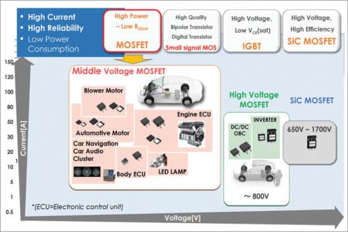
Power device technologies such as silicon-carbide metal oxide semiconductor field effect transistors (SiC MOSFETs), diodes and high-voltage insulated-gate bipolar transistors (IGBTs) improve the performance of EV systems and charging infrastructure. Multi-tasking, application-specific LSI (system ASICs) controllers reduce complexity and size, and improve efficiency of automotive systems.
Automotive green solutions include LED lighting that reduce energy consumption and extend the life of the lamp (generating less waste). SiC products (MOSFETs and Schottky barrier diodes) improve efficiency and robustness of the systems.
The aim now is to develop components for simplifying system designs, and improving efficiency and reliability. Safety and reliability are paramount for automotive systems.
The focus is also on designing development systems that reduce emissions and help original equipment manufacturers (OEMs) meet demanding standards like BS-VI, for both two and four wheelers.
Focus is also on LSI (ASIC) devices for making control systems simpler and more compact.
Steps to ensure quality and reliability of automotive components are:
Steps to ensure quality and reliability of automotive components are:
- At chip level, develop chip design rules like clearances and routing to improve reliability.
- Set up separate wafer processing facilities for automotive products.
- Modify packaging designs to reduce stresses on wire bonds, leads and solder joints, to improve system-level reliability.
- Stick to relevant AEC standards (Q100, Q101) for all automotive parts.
Latest chips for automotives
Satish R.M, automotive product strategy manager, ROHM Semiconductors, says, “ROHM obtained ISO 26262 process certification, which is an international standard for functional safety for automotive products. Focus applications include electronic fuel injection systems (fuel pump controls, etc), regulators/rectifiers, integrated starter generators, body electronics (lighting, displays, etc), traction motor inverters, DC-to-DC controllers, onboard chargers and charging stations for EVs, and body control modules (lighting, mirror control, power windows, etc), among others.”
ROHM offers EV charging applications and other multiple technologies to benefit automotive systems. These are:
- Robust IGBTs with extended short-circuit capabilities for high-voltage applications such as traction inverters. Unlike conventional IGBTs with short-circuit capabilities, these IGBTs suffer minimum performance loss.
- Robust, high-frequency switching devices (SiC MOSFETS up to 1700V ratings) for high-voltage, high-frequency applications such as onboard charging circuits, DC-to-DC converters and charging stations for EVs.
- Full SiC modules with ratings up to 1200V, 600A for high-power converters. These modules help achieve high efficiency for fast-charging DC charging stations for four-wheeled EVs.
Amith Kumar, Technical support, Analog Devices, says, “We provide two latest chips for the automobile industry: LTC6813 and LTC3895. Application areas for these chips are battery management systems for EVs and high-vin DC-to-DC converters. Accuracy and reliability are our prime criteria while designing these chips for automobiles.”
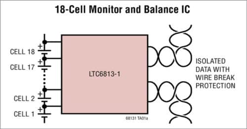
LTC6813 is a multi-cell battery stack monitor, which can measure up to 18 series connected battery cells. Cell measurement range of 0V to 5V with a total measurement error of less than 2.2mV makes it suitable for most battery chemistries. Multiple LTC6813 parts can be connected in series for simultaneous cell monitoring of long, high-voltage battery strings. For high-speed, radio frequency (RF)-immune, long-distance communications, each device has an isoSPI interface.
LTC3895 drives an all n-channel MOSFET power stage. It is a high-voltage, non-isolated synchronous step-down switching regulator controller, designed to operate from a high input voltage source (4V to 140V) or from an input that has high voltage surges. It eliminates the need for external surge suppression devices. When input voltage dips to 4V, it continues to operate at up to 100 per cent duty cycle. This makes it well suited for transportation, robotic industrial control and datacom applications.
Jai Prakash Chauhan, design engineer, NXP Semiconductors, says, “NXP designs and develops advanced electronic systems to safeguard vehicles. Major areas of focus are in-vehicle networks, microcontrollers (MCUs), processors, radars and secure car access.
“Processors are designed for efficient and intelligent communication networks in the vehicle like CAN transceivers and controllers (for high-speed CAN applications); LIN, ISO9141 and J1850 physical interfaces that support various communication protocols; FlexRay transceivers for high-bandwidth applications; LIN transceivers for low-cost communication solutions and system basis chip for integrated automotive MCU-based systems.”
These processors are used for designing advanced driver assistance systems (ADASes), body, chassis, powertrains and safety applications. Some available families are S32, S32K and S32R27 for automotive and industrial radar, S12 and S12X for wide memory and pin scalability, S32S for safety applications, S08 for high performance and low power, S32V for vision-processing applications and MagniV series for mixed-signal applications.
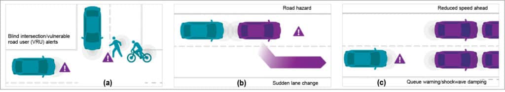
Rajiv Baby, application engineer, Qualcomm, says, “Qualcomm C-V2X 9150 chipset directly connects vehicles to everything (V2X)—to each other, to pedestrians, to roadway infrastructure and to the network. It extends a vehicle’s ability to provide a higher level of predictability for enhanced safety and autonomy, by looking further down the road.
“We have integrated V2X safety services with Wi-Fi-based dedicated short-range communications. C-V2X 9150 is integrated with GNSS capability for accurate positioning. An application processor running intelligent transportation systems V2X stack and hardware security module provides secure V2X communications.”
Researchers all over the world are working on systems-on-chips (SoCs) that integrate all necessary electronic components on a single chip, rather than single application chips. SoCs are used for in-car media to provide powerful solutions for multimedia applications. Examples include AM/FM radio chips, car radio on/off logic chips, audio amplifiers and multi-standard digital radios.
SoCs are also used in advanced motor controls for automotive and industrial applications. Some examples are motor drivers, low-side switches, high-side switches, anti-braking systems, squib drivers, pre-drivers and configurable switches for load control.
These are used in battery and power management, too. High-efficiency switching regulators, and lighting control and power management ICs are some examples.
SoCs have applications in ADAS, including advance features like electronic beam steering for object detection in wide range and safety systems like emergency braking, adaptive cruise control, blind spot monitoring, cross traffic alert and automated parking, among others.
Last, but not the least, SoCs are used for secure and convenient vehicle access and in immobiliser systems. These include technologies such as NFC and RF/UHF link with advanced encryption and protocol support.
E. XO Wireless mesh network
( JOINT WIRELESS )
A wireless mesh network (WMN) is a communications network made up of radio nodes organized in a mesh topology. It is also a form of wireless ad hoc network.
Wireless mesh architecture is a first step towards providing cost effective and low mobility over a specific coverage area. Wireless mesh infrastructure is, in effect, a network of routers minus the cabling between nodes. It is built of peer radio devices that do not have to be cabled to a wired port like traditional WLAN access points (AP) do. Mesh infrastructure carries data over large distances by splitting the distance into a series of short hops. Intermediate nodes not only boost the signal, but cooperatively pass data from point A to point B by making forwarding decisions based on their knowledge of the network, i.e. perform routing by first deriving the topology of the network.
Wireless mesh networks is a relatively "stable-topology" network except for the occasional failure of nodes or addition of new nodes. The path of traffic, being aggregated from a large number of end users, changes infrequently. Practically all the traffic in an infrastructure mesh network is either forwarded to or from a gateway, while in wireless ad hoc networks or client mesh networks the traffic flows between arbitrary pairs of nodes.
If rate of mobility among nodes are high, i.e., link breaks happen frequently, wireless mesh networks start to break down and have low communication performance .
A mesh refers to rich interconnection among devices or nodes. Wireless mesh networks often consist of mesh clients, mesh routers and gateways. Mobility of nodes is less frequent. If nodes constantly or frequently move, the mesh spends more time updating routes than delivering data. In a wireless mesh network, topology tends to be more static, so that routes computation can converge and delivery of data to their destinations can occur. Hence, this is a low-mobility centralized form of wireless ad hoc network. Also, because it sometimes relies on static nodes to act as gateways, it is not a truly all-wireless ad hoc network.
Mesh clients are often laptops, cell phones, and other wireless devices. Mesh routers forward traffic to and from the gateways, which may, but need not, be connected to the Internet. The coverage area of all radio nodes working as a single network is sometimes called a mesh cloud. Access to this mesh cloud depends on the radio nodes working together to create a radio network. A mesh network is reliable and offers redundancy. When one node can no longer operate, the rest of the nodes can still communicate with each other, directly or through one or more intermediate nodes. Wireless mesh networks can self form and self heal. Wireless mesh networks work with different wireless technologies including 802.11, 802.15, 802.16, cellular technologies and need not be restricted to any one technology or protocol. See also mesh networking.

Diagram showing a possible configuration for a wired-wireless mesh network, connected upstream via a VSAT link
Management
This type of infrastructure can be decentralized (with no central server) or centrally managed (with a central server).[4] Both are relatively inexpensive, and can be very reliable and resilient, as each node needs only transmit as far as the next node. Nodes act as routers to transmit data from nearby nodes to peers that are too far away to reach in a single hop, resulting in a network that can span larger distances. The topology of a mesh network must be relatively stable, i.e., not too much mobility. If one node drops out of the network, due to hardware failure or any other reason, its neighbors can quickly find another route using a routing protocol.
Applications
Mesh networks may involve either fixed or mobile devices. The solutions are as diverse as communication needs, for example in difficult environments such as emergency situations, tunnels, oil rigs, battlefield surveillance, high-speed mobile-video applications on board public transport, real-time racing-car telemetry, or self-organizing Internet access for communities.[5] An important possible application for wireless mesh networks is VoIP. By using a quality of service scheme, the wireless mesh may support routing local telephone calls through the mesh. Most applications in wireless mesh networks are similar to those in wireless ad hoc networks.
Some current applications:
- U.S. military forces are now using wireless mesh networking to connect their computers, mainly ruggedized laptops, in field operations.
- Electric smart meters now being deployed on residences, transfer their readings from one to another and eventually to the central office for billing, without the need for human meter readers or the need to connect the meters with cables
- The laptops in the One Laptop per Child program use wireless mesh networking to enable students to exchange files and get on the Internet even though they lack wired or cell phone or other physical connections in their area.
- Google Home, Google Wi-Fi, and Google OnHub all support Wi-Fi mesh (i.e., Wi-Fi ad hoc) networking.[7] Several manufacturers of Wi-Fi routers began offering mesh routers for home use in the mid-2010s.
- The 66-satellite Iridium constellation operates as a mesh network, with wireless links between adjacent satellites. Calls between two satellite phones are routed through the mesh, from one satellite to another across the constellation, without having to go through an earth station. This makes for a smaller travel distance for the signal, reducing latency, and also allows for the constellation to operate with far fewer earth stations than would be required for 66 traditional communications satellites.
Operation
The principle is similar to the way packets travel around the wired Internet—data hops from one device to another until it eventually reaches its destination. Dynamic routing algorithms implemented in each device allow this to happen. To implement such dynamic routing protocols, each device needs to communicate routing information to other devices in the network. Each device then determines what to do with the data it receives – either pass it on to the next device or keep it, depending on the protocol. The routing algorithm used should attempt to always ensure that the data takes the most appropriate (fastest) route to its destination.
Multi-radio mesh
Multi-radio mesh refers to having different radios operating at different frequencies to interconnect nodes in a mesh. This means there is a unique frequency used for each wireless hop and thus a dedicated CSMA collision domain. With more radio bands, communication throughput is likely to increase as a result of more available communication channels. This is similar to providing dual or multiple radio paths to transmit and receive data.
Research topics
One of the more often cited papers on Wireless Mesh Networks identified the following areas as open research problems in 2005
- New modulation scheme
- Advanced antenna processing
- Advanced antenna processing including directional, smart and multiple antenna technologies is further investigated, since their complexity and cost are still too high for wide commercialization.
- Flexible spectrum management
- Tremendous efforts on research of frequency-agile techniques are being performed for increased efficiency.
- Cross-layer optimization
- Cross-layer research is a popular current research topic where information is shared between different communications layers to increase the knowledge and current state of the network. This could facilitate development of new and more efficient protocols. A joint protocol that addresses various design problems—routing, scheduling, channel assignment etc.—can achieve higher performance since these problems are strongly co-related.[9] Note that careless cross-layer design can lead to code that is difficult to maintain and extend.
- Software-defined wireless networking
- Centralized, distributed, or hybrid? - In a new SDN architecture for WDNs is explored that eliminates the need for multi-hop flooding of route information and therefore enables WDNs to easily expand. The key idea is to split network control and data forwarding by using two separate frequency bands. The forwarding nodes and the SDN controller exchange link-state information and other network control signaling in one of the bands, while actual data forwarding takes place in the other band.
- Security
- A WMN can be seen as a group of nodes (clients or routers) that cooperate to provide connectivity. Such an open architecture, where clients serve as routers to forward data packets, is exposed to many types of attacks that can interrupt the whole network and cause denial of service (DoS) or Distributed Denial of Service (DDoS).
Protocols
Routing protocols
There are more than 70 competing schemes for routing packets across mesh networks. Some of these include:
- Associativity-Based Routing (ABR)
- AODV (Ad hoc On-Demand Distance Vector)
- B.A.T.M.A.N. (Better Approach To Mobile Adhoc Networking)
- Babel (protocol) (a distance-vector routing protocol for IPv6 and IPv4 with fast convergence properties)
- Dynamic NIx-Vector Routing|DNVR
- DSDV (Destination-Sequenced Distance-Vector Routing)
- DSR (Dynamic Source Routing)
- HSLS (Hazy-Sighted Link State)
- HWMP (Hybrid Wireless Mesh Protocol, the default mandatory routing protocol of IEEE 802.11s)
- Infrastructure Wireless Mesh Protocol (IWMP) for Infrastructure Mesh Networks by GRECO UFPB-Brazil[14]
- OLSR (Optimized Link State Routing protocol)
- OORP (OrderOne Routing Protocol) (OrderOne Networks Routing Protocol)
- OSPF (Open Shortest Path First Routing)
- Routing Protocol for Low-Power and Lossy Networks (IETF ROLL RPL protocol, RFC 6550)
- PWRP (Predictive Wireless Routing Protocol)
- TORA (Temporally-Ordered Routing Algorithm)
- ZRP (Zone Routing Protocol)
A less thorough list can be found at Ad hoc routing protocol list.
Autoconfiguration protocols
Mesh network specific autoconfiguration protocols include:Standard autoconfiguration protocols, such as DHCP or IPv6 stateless autoconfiguration may be used over mesh networks.
- Ad Hoc Configuration Protocol (AHCP)
- Proactive Autoconfiguration (Proactive Autoconfiguration Protocol)
- Dynamic WMN Configuration Protocol (DWCP)
++++++++++++++++++++++++++++++++++++++++++++++++++++++++++++++++++++++++
THE JOINT ( Jump In On Through )

++++++++++++++++++++++++++++++++++++++++++++++++++++++++++++++++++++++++
This is what commonly happens to the newbies in the business industry who do not know how to effectively market their product or service or service.Alternatives to GoGo Anime
BalasHapusThanks for sharing nice information about plastic finger support protector for fingers joint pain with us. i glad to read this post.
BalasHapus