
Data Communication Interfaces

Call it the Internet of Things, or distributed systems, or whatever the term of the day happens to be, but it is a fact that for a gadget to be as useful as it possibly can be, it needs to be able to exchange data with other things. After all, a gadget sitting all by itself in the corner with nothing to talk to is a lonely gadget.
In the past, communication of data between various devices and systems was accomplished through slow RS-232 or 20 mA current loop serial links, or bulky portable media such as magnetic tapes, removable disk packs, and floppy disks. Early in the history of computing, punched paper cards and rolls of punched paper tape were initially used for this purpose.
Nowadays, we have USB flash drives, SD memory cards, portable hard drives, and Bluetooth, USB, WiFi, and Ethernet communications. But the end result is the same: data from one device or system is passed to another for processing, storage, or display (or all three), just a lot faster today than 10, 20, or 40 years ago. Sharing data in real time is now a commonplace feature of things like networked refrigerators, coffee pots, thermostats, and home .

Electronic interfaces
Interfacing is a term used in electronics when different electronic devices are connected in order to move information from one device to another. This information may take the form of instructions for the function of a device, or feedback from a device about the results of executing a function. Laboratory automation devices function to either measure and/or act to control physical process. Electronic interfacing in laboratory automation spans a very wide range of sophistication and complexity, but in general does not tend to be cutting edge, simply because the demands placed on the interface are usually moderate. The information passed through an interface may be very simple, such as a two-state signal, high or low, open or closed. Or it may be a complex, binary stream of serial or parallel data. Data rates can range from hundreds to giga-bits of information per second.
Analog
Electrical quantities of voltage and current are easy to measure, manipulate, and transmit over long distances, so they are widely used in analog form to represent physical variables and transmit information to/from remote locations. An analog signal refers to an electrical quantity of voltage or current, used to represent or signify some other physical quantity. The signal is continuously variable, as opposed to having a limited number of steps along its range (digital).
Voltage based signals
DC voltage can be used as an analog signal to relay information from one location to another.[1] Circuits can be designed allowing the DC voltage level at the signal source to be an indicator of the physical state of a device, or a measurement. One common signal standard is 0-10 volts, meaning that a signal of 0 volts represents 0 % of measurement, 10 volts represents 100 % of measurement, and 5 volts represents 50 % of measurement. A more common voltage range is 1-5 volts, with 1 volt representing 0% measurement, 5 volts representing 100% of measurement and <1 volt indicating a circuit proactol plus fault. Using a voltage offset above zero to indicate a 0% state is referred to as using a "live zero", a standard way of scaling a signal so that an indication of 0 % can be discriminated from the status of a "dead" or faulted system. A major disadvantage of voltage signaling is the possibility that the voltage at the indicator will be less than the voltage at the signal source, due to line resistance and indicator current draw. This drop in voltage along the conductor length constitutes a measurement error from transmitter to indicator.
Current based signals
It is possible through the use of electronic amplifiers to design a circuit outputting a constant amount of current rather than a constant amount of voltage.[2] Current sources can be built as variable devices, just like voltage sources, and they can be designed to produce very precise amounts of current as an indicator of the physical state of a device or a measurement. The most common current signal standard in modern use is the 4 to 20 milliamp (4-20 mA) loop, with 4 milliamps representing 0 percent of measurement, 20 milliamps representing 100 percent, and 12 milliamps representing 50 percent. A convenient feature of the 4-20 mA standard is its ease of signal conversion to 1-5 volt indicating instruments. A 250 ohm precision resistor connected in series with the circuit will produce 1 volt of drop at 4 milliamps, 5 volts of drop at 20 milliamps. As opposed to a voltage based signals, a current "loop" circuit relies on the series circuit principle of current being equal through all components to insure no signal error due to wiring resistance.
Analog current loops are used where a device must be monitored or controlled remotely over a pair of conductors. Analog 4-20 mA current loops are commonly used for signaling in industrial process control instruments, especially when signaling must occur over long distances (1000 feet or more)[3]. The key advantages of the current loop are that the accuracy of the signal is not affected by voltage drop in the interconnecting wiring, and that the loop can supply operating power to the device. Such instruments are used to measure pressure, temperature, flow, pH or other process variables. A current loop can also be used to control a valve positioner or other output actuator. A commonly used control device called a programmable logic controller, or a PLC, is used to read a set of digital and analog inputs, apply a set of logic statements, and generate a set of analog and digital outputs.
Digital
Contact closure, TTL I/O
Already in the binary language of computers, these types of digital, or discrete, inputs and outputs (I/O) are much easier for microprocessor-based data acquisition systems to deal with than analog signals. Digital I/O is designed to deal directly with Transistor-to-Transistor Logic (TTL) level voltage changes. TTL typically sets the low voltage level between 0 and 0.8 V and the high voltage level between 2.0 and 5.0 V. Voltage levels between 0.8 and 2.0 V are not allowed. A voltage change, then, from the high range to the low range (or vice versa) represents a digital change of state from high to low, on to off, etc.
Digital Input
- The most common type of digital input is the contact, or switch closure. A sensor or switch of some type closes or opens a set of contacts in accordance with some process change. An applied electrical signal then determines whether the circuit is open or closed. Current flows if the circuit is closed, registering a "1" at the computer interface circuitry. Conversely, an open circuit retains a high voltage (and no current), registering a "0" at the computer interface circuitry. Laboratory automation systems often use switch closures to provide input regarding mechanical positioning of a device, and are particularly useful in error detection.
Digital Output
- A simple digital output provides a means of turning something on or off. Applications range from driving a relay to turning on an indicator lamp to transmitting data to another capsiplex computer. For latching outputs, a "1" typically causes the associated switch or relay to latch, while a "0" causes the switch to unlatch. Devices can be turned on or off, depending on whether the external contacts are normally open or normally closed. Standard TTL level signals can be used to drive 5-V relay coils, but are intended primarily to drive other logic slim weight patch circuits, not final control elements, such as solenoids, motors, or alarms. Many analog transducers that sense continuous variables such as pressure and temperature, can be purchased with imbedded circuitry to provide an output that is one of two states: high or low, open or closed, based on a set-point. A pressure might be too high or a temperature too low, triggering closure of a switch.
Digital I/O cards
- Data I/O cards that plug into the chassis, or the USB, RS-232 or GPIB port of a desktop PC or a PC-compatible industrial computer have made measurement and control extremely economical for the typical lab automation user. Many types of analog and digital signals can be input or output directly by performer 5 digital I/O cards, including analog current loop, switch closures, relay contacts, or TTL I/O. Cards with as many as 64 I/O channels are available from a variety of vendors.
Serial interfaces
Serial data is any data that is sent one bit at a time using a single electrical signal. In a serial interface the serial port takes 8, 16, 32 or 64 parallel bits from the computer bus and converts it as an 8, 16, 32 or 64 bit serial stream. In contrast, parallel data is sent 8, 16, 32, or 64 bits at a time using a signal line for each bit. In theory a serial link needs only two wires, a signal line and a ground, to move the serial signal from one location to another. But in practice this doesn't really work for very long, as some bits get lost in the signal and alter the ending result. If one bit is missing at the receiving end, all succeeding bits are shifted resulting in incorrect data when converted back to a parallel signal. Two serial transmission methods are used that correct serial bit errors. With synchronous communication, the sending and receiving ends of the communication are synchronized using a clock that precisely times the period separating each bit. By checking the clock the receiving end can determine if a bit is missing or if an extra bit (usually electrically induced) has been introduced in the stream. The alternative method (used in PCs) is to add markers within the bit stream to help track each data bit. By introducing a start bit which indicates the start of a short HGH Advanced data stream, the position of each bit can be determined by timing the bits at regular intervals. By sending start bits in front of each 8 bit stream, the two systems don't have to be synchronized by a clock signal. The only important issue is that both systems must be set at the same port speed. When the receiving end of the communication receives the start bit it starts a short term timer. By keeping streams short, there's not enough time for for the timer to get out of sync. This method is known as asynchronous communication because the sending and receiving end of the communication are not precisely synchronized by the means of a signal line.
Serial communication is used for all long-haul communication and most computer networks, where the cost of cable and synchronization difficulties make parallel communication clear skin max impractical. At shorter distances, serial computer buses are becoming more common because of simplicity and improved technology to ensure signal integrity and to transmit and receive at a sufficiently high speed.
| Serial Interface Quick Facts | |||
| Type | Maximum Speed | Number of Device Connections | Maximum Distance |
| RS232 | 20 Kbps | 1 | 50 feet @ 20Kbps, 3000 feet @ 2.4Kbps |
| RS422 | 10 Mbps | 10 | |
| RS485 | 10 Mbps | 32 | 4000 feet |
| CAN | 1 Mbps | 30 | 328 feet @ 12 Mbps, 3330' @ 1 Mbps |
| USB 2.0 | 480 Mbps | 127 | 10 feet (up to 60' with hubs) |
| IEEE1394c | 3200 Mbps | 63 | 15 feet (250' with repeaters) |
| Ethernet | 10 Gbps | 255 | 328 feet (longer with hubs, switches) |
The 2008 ALA Survey of Technology Providers asked a dozen prominent laboratory automation technology providers about the electronic interfaces used in their products. The results indicate that RS-232 still is the most widely used electronic interface, with Ethernet a close second. Projections for 5 years out show Ethernet becoming the dominating interface technology. It should be noted, however, that the demise of RS-232 has long been predicted, but has yet to happen.
| 2008 ALA Survey of Technology Providers | ||
| Interface | % of devices using interface in 2008 | % of devices using interface in 2013 (predicted) |
| RS-232 / RS-485 | 45% | 31% |
| Ethernet | 42% | 55% |
| USB | 25% | 38% |
| CAN bus | 13% | 11% |
| IEEE-1394/Firewire | 10% | 9% |
| GPIB | 8% | 7% |
| Bluetooth / Wireless | 8% | 21% |
EIA/TIA-232E (RS-232)

RS-232 / Current loop converter
The Electronics Industries Association (EIA) recommended standard RS-232-C[4] is a standard originally devised for serial binary data signals connecting between a DTE (Data Terminal Equipment) and a DCE (Data Circuit-terminating Equipment) in 1969. It has since become commonly used in computer serial ports. Since 1969, manufacturers adopted simplified versions of this interface for applications that were impossible to envision in the 1960s. The current slimming reviews revision is the Telecommunications Industry Association TIA-232-F Interface Between Data Terminal Equipment and Data Circuit-Terminating Equipment Employing Serial Binary Data Interchange, issued in 1997. Because no single "simplified" standard was agreed upon, however, many slightly different protocols and cables were created that obligingly mate with any EIA232 connector, but are incompatible with each other. RS-232 defines the purpose and signal timing for each of 25 data lines; however, many applications use less than a dozen.
RS232 is still widely used in laboratory automation, as well as other industries. For laboratory automation systems, the interface provides sufficient speed for most interface needs and is simple and low cost. One drawback is the ability to connect only one device per RS232 port. Relatively inexpensive port expander cards or external expansion boxes are readily available to overcome this limitation. Another limitation is that most current default PC configurations do not include an RS-232 interface port. Adapters are available to convert newer serial ports (e.g. USB) to RS-232 outputs. A major drawback is and always will be the lack of true standardization.
RS-232 vs. TTL Serial Communication
One of the tools we use most when debugging our projects is serial input/output. Serial is very easy to implement, and it allows you to send/receive any data you need from your microcontroller to a computer's serial port so it can be viewed using a terminal emulator. These two devices are compatible from a software perspective, however you can't just hook a microcontroller up to a computer because the hardware interfaces are not compatible.
Most microcontrollers these days have built in UARTs (universally asynchronous receiver/transmitter) that can be used to receive and transmit data serially. UARTs transmit one bit at a time at a specified data rate (i.e. 9600bps, 115200bps, etc.). This method of serial communication is sometimes referred to as TTL serial (transistor-transistor logic). Serial communication at a TTL level will always remain between the limits of 0V and Vcc, which is often 5V or 3.3V. A logic high ('1') is represented by Vcc, while a logic low ('0') is 0V.
The serial port on your computer (if it's lucky enough to have one, they're quickly becoming a relic) complies with the RS-232 (Recommended Standard 232) telecommunications standard. RS-232 signals are similar to your microcontroller's serial signals in that they transmit one bit at a time, at a specific baud rate, with or without parity and/or stop bits. The two differ solely at a hardware level. By the RS-232 standard a logic high ('1') is represented by a negative voltage – anywhere from -3 to -25V – while a logic low ('0') transmits a positive voltage that can be anywhere from +3 to +25V. On most PCs these signals swing from -13 to +13V.
The more extreme voltages of an RS-232 signal help to make it less susceptible to noise, interference, and degradation. This means that an RS-232 signal can generally travel longer physical distances than their TTL counterparts, while still providing a reliable data transmission.

This timing diagram shows both a TTL (bottom) and RS-232 signal sending 0b01010101
Solutions
So, you may see where the problem lies in interfacing these two signals. To connect these two ports you not only have to invert the signals, but you also have to deal with regulating the potentially harmful RS-232 voltages to something that won't destroy a microcontroller's serial pins. There are a handful of solutions to this problem of voltage converting and inverting. The most common, and easiest solution is just plugging a MAX-232 in between the two devices:

There are many generic derivatives of the MAX-232. Maxim IC just happened to be the first to market with this neato device (decades ago!) so out of habit, we call all ICs that do similar jobs 'MAX-232s'.
Less expensive solutions, like our RS-232 Shifter, use transistors or inverters to flip the signals, and charge pumps to get the voltages high enough to be RS-232 compliant:
Sample Question
With the above information at hand, here's a quick quiz to test your shiny new knowledge:
1. What are the two main differences between RS-232 and TTL signals?
2. True or false: Data is sent from a PC's RS-232 port at 9600 bits-per-second (bps), it's converted to TTL by a MAX232 before reaching a microcontroller. The voltages of the signals look different on each end, but the speed (bps) does not change.
EIA/TIA-485 (RS-485)
In telecommunications, EIA-485 (formerly RS-485 or RS485) is an electrical specification of a two-wire, half-duplex, multipoint serial communications channel. The architectural difference between Phen375 RS-232 and RS-485 is that RS-232 is a bi-directional point to point link, whereas RS-485 is a single channel, multi-point bus that can support multiple drivers and multiple receivers, with up to 32 interfaced devices. RS-485 is a "differential" standard. In addition to a common signal, there are two transmit lines (Tx+ and Tx-) and two receive lines (Rx+ and Rx-). The receiving end of the transmission line uses the difference of voltage on the pairs. This greatly reduces noise susceptibility and, in most cases, RS-485 supports longer transmission distances (up to 4,000 feet) and higher speeds (10 Mbps) than RS-232. However, it is not nearly as common as RS-232. RS-232 can also carry additional signals used for flow control and modem control. Only one device on a RS-485 bus can transmit at a time, whereas there are separate dedicated transmit and receive channels for the single device at the other end of a RS-232 link. There must also be external hardware that enables driving the bus when transmitting. EIA-485 does not specify any connector or pinout. Circuits may be terminated on screw terminals, D-subminiature connectors, or other types of connectors.
EIA-485 is used in building automation as the simple bus wiring and long cable length is ideal for joining remote devices, such as surveillance cameras or card readers. It has minimal presence in laboratory automation.
Universal Serial Bus (USB)
The Universal Serial Bus (USB) is a serial bus standard to interface devices to a host computer. USB was designed to replace many legacy serial and parallel interfaces and allow many peripherals to be connected using a single standardized interface socket. The design of USB is standardized by the USB Implementers Forum (USB-IF), an industry standards body formed in 1995 to support and accelerate market and consumer adoption of USB-compliant peripherals. The USB 1.0 specification model was introduced in November 1995. The current (as of 2008) USB 2.0 specification, with a design data rate of 480 megabits per second, was released in April 2000 and was standardized by the USB-IF at the end of 2001. A draft specification for USB 3.0 (data rate of 4.8 Gbit/s (600 MB/s)) was released by Intel and its partners in August 2008. According to Intel, bus speeds will be 10 times faster than USB 2.0 due to the inclusion of a fibre-optic link that works with traditional copper connectors. Products using the 3.0 specification are likely to arrive in 2009 or 2010.
Despite becoming the interface of choice for consumer PC peripherals, USB is not highly popular in laboratory automation devices. It is most commonly found in simple devices, such as balances, whose primary market is stand-alone bench use, rather than integration into automation systems. The cable length limits without using hubs may be a contributing factor.
IEEE-1394
The IEEE 1394 interface is a serial bus interface standard for high-speed communications and isochronous real-time data transfer, frequently used in a personal computer, digital audio and digital video. The 1394 digital link standard was conceived in 1986 by technologists at Apple Computer, who chose the trademark 'FireWire', in reference to its speeds of operation. The first specification for this link was completed in 1987. It was adopted in 1995 as the IEEE 1394 standard. The interface is also known by the brand names of i.LINK (Sony) and Lynx (Texas Instruments). FireWire can connect up to 63 peripherals in a tree topology and allows peer-to-peer device communication — such as communication between a scanner and a printer — to take place without using system memory or the CPU. The newer, current IEEE 1394b (Fire standard was introduced commercially by Apple in 2003. It allows a transfer rate of 786.432 Mbit/s full-duplex via 9 pin connector, and is backwards compatible to the 6 pin configuration and slower data rates of the original IEEE 1394a standard. The full IEEE 1394b specification supports data rates up to 3200 Mbit/s over beta-mode or optical connections up to 100 metres in length. In December 2007, the 1394 Trade Association announced that products will be available before the end of 2008 using the S1600 and S3200 modes that, for the most part, had already been defined in 1394b. The 1.6 Gbit/s and 3.2 Gbit/s devices will use the same 9-pin connectors as the existing FireWire 800 and will be fully compatible with existing S400 and S800 devices. It will compete with the forthcoming USB 3.0.. IEEE 1394b is used in military aircraft and automobiles, where weight savings are important, as well as with computer vision and digital video cameras.
The most common usage of IEEE-1394 interfacing in the laboratory is with high data density imaging devices.
Controller Area Network (CAN)
The controller-area network (CAN or CAN-bus) is a computer network protocol and bus standard designed to allow microcontrollers and devices to communicate with each other without a host computer. It was designed specifically for automotive applications but is now also used in other embedded control applications . Development of the CAN-bus started originally in 1983 at Robert Bosch GmbH.[7] The protocol was officially released in 1986 at the SAE (Society of Automotive Engineers) congress in Detroit. The first CAN controller chips, produced by Intel and Philips, came on the market in 1987. Bosch published the CAN 2.0 specification in 1991. CAN is a broadcast, differential serial bus standard for connecting electronic control units (ECUs). Each node is able to send and receive messages, but not simultaneously. The devices that are connected by a CAN network are typically sensors, actuators and control devices. A CAN message never reaches these devices directly, but instead a host-processor and a CAN Controller is needed between these devices and the bus.
CAN technology is used in automobiles, industrial control applications, and in some medical and laboratory instrumentation (Agilent, Beckman-Coulte ). It is more often used as embedded control approachnot vs. a user-accessible general purpose interface methodology, such as RS-232 or USB.
Parallel interfaces
A parallel interface is a link between two devices in which all the information transferred between them is transmitted simultaneously over separate conductors. Also known as parallel port. Before the development of high-speed serial technologies, the choice of parallel links over serial links was driven by these factors:
- Speed: Superficially, the speed of a parallel data link is equal to the number of bits sent at one time times the bit rate of each individual path; doubling the number of bits sent at once doubles the data rate. In practice, skew reduces the speed of every link to the slowest of all of the links.
- Cable length: Crosstalk creates interference between the parallel lines, and the effect worsens with the length of the communication link. This places an upper limit on the length of a parallel data connection that is usually shorter than a serial connection.
- Complexity: Parallel data links are easily implemented in hardware, making them a logical choice. Creating a parallel port in a computer system is relatively simple, requiring only a latch to copy data onto a data bus. In contrast, most serial communication must first be converted back into parallel form by a Universal asynchronous receiver transmitter before they may be directly connected to a data bus.
The decreasing cost of integrated circuits, combined with greater consumer demand for speed and cable length, has led to parallel communication links becoming deprecated in favor of serial links; for example, IEEE 1284 printer ports vs. USB, Advanced Technology Attachment (ATA) vs. Serial ATA, SCSI vs. FireWire (IEEE-1394).
IEEE-1284
An early parallel interface was developed by Dr. An Wang, Robert Howard and Prentice Robinson at Wang Laboratories. The now-familiar connector was selected because Wang had a surplus stock of 20,000 Amphenol 36-pin micro ribbon connectors that were originally used for one of their early calculators. The Centronics Model 101 printer was introduced in 1970 and included this parallel interface for printers. The Centronics parallel interface quickly became a de facto industry standard.The IEEE 1284 standard superseded the Centronics interface in 1994. The IEEE 1284 standard allows for faster throughput and bidirectional data flow with a theoretical maximum throughput of 4 megabits per second, with actual throughput around 2 megabits, depending on hardware. The parallel interface remains highly popular in the printer industry, with displacement by USB only in consumer models.
IEEE-1284 interfaces have been used in the laboratory automation environment primarily for to interface imaging or printing devices (scanners, bar code printers). In many cases, the USB interface has now been added to such devices or has replaced the parallel interface.
IEEE-488
The IEEE-488 is a short-range, digital communications bus specification. The IEEE-488 bus was developed to connect and control programmable instruments, and to provide a standard interface for communication between instruments from different sources, and is still widely used for test and measurement equipment today. Hewlett-Packard originally developed the interfacing technique, and called it HP-IB. The interface quickly gained popularity in the computer industry. Because the interface was so versatile, the IEEE committee renamed it GPIB (General Purpose interface Bus). In 1975 the bus was standardized by the Institute of Electrical and Electronics Engineers as the IEEE Standard Digital Interface for Programmable Instrumentation, IEEE-488-1975 (now 488.1). IEEE-488.1 formalized the mechanical, electrical, and basic protocol parameters of GPIB, but said nothing about the format of commands or data. .
The IEEE-488 connector has 24 pins. The bus employs 16 signal lines — eight bi-directional used for data transfer, three for handshake, and five for bus management — plus eight ground return lines. The maximum data rate is about 8 Mbyte/s in the latest versions.
The IEE-488 interface is still a standard feature of laboratory instruments built by Agilent (formerly Hewlett-Packard). Few, if any, other laboratory equipment providers have adopted the interface.
SCSI
Small Computer System Interface , or SCSI (skuh-zee), is a set of standards for physically connecting and transferring data between computers and peripheral devices. The SCSI standards define commands, protocols, and electrical and optical interfaces. SCSI is most commonly used for hard disks and tape drives, but it can connect a wide range of other devices, including scanners and CD drives. The SCSI standard defines command sets for specific peripheral device types; the presence of "unknown" as one of these types means that in theory it can be used as an interface to almost any device, but the standard is highly pragmatic and addressed toward commercial requirements. SCSI is based on an older, proprietary bus interface called Shugart Associates System Interface (SASI). SASI was originally developed in 1981 by Shugart Associates in conjunction with NCR Corporation. In 1986, the American National Standards Institute (ANSI) ratified SCSI (pronounced "scuzzy"), a modified version of SASI.
SCSI has several benefits. It supports speeds up to 320 megabytes per second (MBps). It's been around for more than 20 years and it's been thoroughly tested, so it has a reputation for being reliable. Like Serial ATA and FireWire, it lets you put multiple items on one bus. SCSI also works with most computer systems. However, SCSI also has some potential problems. It has limited system BIOS support, and it has to be configured for each computer. There's also no common SCSI software interface. Finally, all the different SCSI types have different speeds, bus widths and connectors.
SCSI is often used to control a redundant array of independent discs (RAID). Other technologies, like serial-ATA (SATA), have largely replaced it in new systems, but SCSI is still in use. Newer SATA drives tend to be faster and cheaper than SCSI drives.
Cables and connectors
A SCSI controller coordinates between all of the other devices on the SCSI bus and the computer. Also called a host adapter, the controller can be a card that you plug into an available slot or it can be built into the motherboard. The SCSI BIOS is also on the controller. This is a small ROM or Flash memory chip that contains the software needed to access and control the devices on the bus. Each SCSI device must have a unique identifier (ID) in order for it to work properly. For example, if the bus can support sixteen devices, their IDs, specified through a hardware or software setting, range from zero to 15. The SCSI controller itself must use one of the IDs, typically the highest one, leaving room for 15 other devices on the bus.
Internal devices connect to a SCSI controller with a ribbon cable. External SCSI devices attach to the controller in a daisy chain using a thick, round cable. (Serial Attached SCSI devices use SATA cables.) In a daisy chain, each device connects to the next one in line. For this reason, external SCSI devices typically have two SCSI connectors -- one to connect to the previous device in the chain, and the other to connect to the next device. The cable itself typically consists of three layers:
- Inner layer: The most protected layer, this contains the actual data being sent.
- Media layer: Contains the wires that send control commands to the device.
- Outer layer: Includes wires that carry parity information, which ensures that the data is correct.
Different SCSI variations use different connectors, which are often incompatible with one another. These connectors usually use 50, 68 or 80 pins. SAS uses smaller, SATA-compatible connectors. If the SCSI bus were left open, electrical signals sent down the bus could reflect back and interfere with communication between devices and the SCSI controller. The solution is to terminate the bus, closing each end with a resistor circuit. If the bus supports both internal and external devices, then the last device on each series must be terminated.
Types of SCSI termination can be grouped into two main categories: passive and active. Passive termination is typically used for SCSI systems that run at the standard clock speed and have a distance of less than 3 feet (1 m) from the devices to the controller. Active termination is used for Fast SCSI systems or systems with devices that are more than 3 feet (1 m) from the SCSI controller.
Laboratory Use
The SCSI interface has primarily been used for the interface of high data rate devices, such as disk drives, both internal and external to the computer. In laboratory equipment, it is most often used as an interface for digital imaging devices.
Network interfaces
A network is a collection of computers or devices connected to each other with the ability to exchange data and or share resources.[11] A network interface is the point of interconnection between a computer and a private or public network. Networks operate using serial communication. Examples of different networks are:
- Local area network (LAN), which is usually a small network constrained to a small geographic area. Computers and devices are linked via Ethernet Cable, can be joined either directly or via a network router that allows multiple connections.
- Wide area network (WAN) that is usually a larger network that covers a large geographic area. The largest and best example of a WAN is the Internet, which is a network comprised of many smaller networks. The Internet is considered the largest network in the world.. The PSTN (Public Switched Telephone Network) also is an extremely large network that is converging to use Internet technologies, although not necessarily through the public Internet.
- Wireless LANs and WANs (WLAN & WWAN) are the wireless equivalent of the LAN and WAN.
- An intranet is a private network within an organization that uses the same communications protocols as the Internet. When part of an intranet is made accessible to suppliers, customers or others outside the organization, that part becomes an extranet.
- An internet (spelled with a lower case i) is a network that is composed of a number of smaller computer networks. The Internet (spelled with an upper case I) is the world-wide network of interconnected internets that operates using a standardized set of communications protocols called TCP/IP (transmission control protocol/Internet protocol), or the Internet protocol suite. This ultimate internet is vastly larger than any other internet and connects thousands of networks and hundreds of millions of computers throughout the world.
All networks are interconnected to allow communication with a variety of different kinds of media, including twisted-pair copper wire cable, coaxial cable, optical fiber, and various wireless technologies. The devices can be separated by a few meters (e.g. via Bluetooth) or nearly unlimited distances (e.g. via the interconnections of the Internet).
Ethernet
Ethernet is a physical and data link layer technology for local area networks (LANs). Ethernet is standardized as IEEE 802.3. The combination of the twisted pair versions of Ethernet for connecting end systems to the network, along with the fiber optic versions for site backbones, is the most widespread wired LAN technology. When first widely deployed in the 1980s, Ethernet supported a maximum theoretical slimming pills data rate of 10 megabits per second (Mbps). Later, Fast Ethernet standards increased this maximum data rate to 100 Mbps. Today, Gigabit Ethernet technology teeth whitener reviews further extends peak performance up to 1000 Mbps. Higher level network protocols like Internet Protocol (IP) use Ethernet as their transmission medium. Data travels over Ethernet inside protocol units called frames. The run length of individual Ethernet unique hoodia cables is limited to roughly 100 meters, but Ethernet can be bridged to easily network entire buildings. Most manufacturers now build the functionality of an Ethernet card directly into PC motherboards, obviating the need for installation of a separate network card.
Ethernet uses 8 position modular connectors (8P8C), often called RJ45, based on the telecommunications standard TIA/EIA-568-B, which defines a hierarchical cable system architecture The cables usually used are four-pair or above twisted pair cable. Each of the three standards support both full-duplex and half-duplex communication. According to the standards, they all operate over distances of 'up to 100 meters'.
Ethernet interfaces are becoming more common in laboratory automation and instrumentation, although still not approaching the level of use of RS-232. Most laboratory instruments do not need the speed offered by Ethernet, but the ease of use and standardization of the modular connectors make the interface appealing. The cost of including an Ethernet phen375 fat burner connection in laboratory equipment has long been a barrier, especially compared to RS-232, but the widespread use of the network interface has significantly lowered the cost. Some instrument providers offer serial to network interfaces for their serial interface-equipped devices. Other laboratory equipment offers network capability as an optional add-on.
XO___XO Computer network
A computer network, or data network, is a digital telecommunications network which allows nodes to share resources. In computer networks, computing devices exchange data with each other using connections (data links) between nodes. These data links are established over cable media such as wires or optic cables, or wireless media such as WiFi.
Network computer devices that originate, route and terminate the data are called network nodes.[1] Nodes are identified by network addresses and can include hosts such as personal computers, phones, servers as well as networking hardware. Two such devices can be said to be networked together when one device is able to exchange information with the other device, whether or not they have a direct connection to each other. In most cases, application-specific communications protocols are layered (i.e. carried as payload) over other more general communications protocols. This formidable collection of information technology requires skilled network management to keep it all running reliably.
Computer networks support an enormous number of applications and services such as access to the World Wide Web, digital video, digital audio, shared use of application and storage servers, printers, and fax machines, and use of email and instant messaging applications as well as many others. Computer networks differ in the transmission medium used to carry their signals, communications protocols to organize network traffic, the network's size, topology, traffic control mechanism and organizational intent. The best-known computer network is the Internet.
Computer networking may be considered a branch of electrical engineering, electronics engineering, telecommunications, computer science, information technology or computer engineering, since it relies upon the theoretical and practical application of the related disciplines.
A computer network facilitates interpersonal communications allowing users to communicate efficiently and easily via various means: email, instant messaging, online chat, telephone, video telephone calls, and video conferencing. A network allows sharing of network and computing resources. Users may access and use resources provided by devices on the network, such as printing a document on a shared network printer or use of a shared storage device. A network allows sharing of files, data, and other types of information giving authorized users the ability to access information stored on other computers on the network. Distributed computing uses computing resources across a network to accomplish tasks.
A computer network may be used by security hackers to deploy computer viruses or computer worms on devices connected to the network, or to prevent these devices from accessing the network via a denial-of-service attack.
Network packet
Computer communication links that do not support packets, such as traditional point-to-point telecommunication links, simply transmit data as a bit stream. However, most information in computer networks is carried in packets. A network packet is a formatted unit of data (a list of bits or bytes, usually a few tens of bytes to a few kilobytes long) carried by a packet-switched network. Packets are sent through the network to their destination. Once the packets arrive they are reassembled into their original message.
Packets consist of two kinds of data: control information, and user data (payload). The control information provides data the network needs to deliver the user data, for example: source and destination network addresses, error detection codes, and sequencing information. Typically, control information is found in packet headers and trailers, with payload data in between.
With packets, the bandwidth of the transmission medium can be better shared among users than if the network were circuit switched. When one user is not sending packets, the link can be filled with packets from other users, and so the cost can be shared, with relatively little interference, provided the link isn't overused. Often the route a packet needs to take through a network is not immediately available. In that case the packet is queued and waits until a link is free.
Network topology
The physical layout of a network is usually less important than the topology that connects network nodes. Most diagrams that describe a physical network are therefore topological, rather than geographic. The symbols on these diagrams usually denote network links and network nodes.
Network links
The transmission media (often referred to in the literature as the physical media) used to link devices to form a computer network include electrical cable, optical fiber, and radio waves. In the OSI model, these are defined at layers 1 and 2 — the physical layer and the data link layer.
A widely adopted family of transmission media used in local area network (LAN) technology is collectively known as Ethernet. The media and protocol standards that enable communication between networked devices over Ethernet are defined by IEEE 802.3. Ethernet transmits data over both copper and fiber cables. Wireless LAN standards use radio waves, others use infrared signals as a transmission medium. Power line communication uses a building's power cabling to transmit data.
Wired technologies

The following classes of wired technologies are used in computer networking.
- Coaxial cable is widely used for cable television systems, office buildings, and other work-sites for local area networks. Transmission speed ranges from 200 million bits per second to more than 500 million bits per second.[citation needed]
- ITU-T G.hn technology uses existing home wiring (coaxial cable, phone lines and power lines) to create a high-speed local area network.
- Twisted pair cabling is used for wired Ethernet and other standards. It typically consists of 4 pairs of copper cabling that can be utilized for both voice and data transmission. The use of two wires twisted together helps to reduce crosstalk and electromagnetic induction. The transmission speed ranges from 2 Mbit/s to 10 Gbit/s. Twisted pair cabling comes in two forms: unshielded twisted pair (UTP) and shielded twisted-pair (STP). Each form comes in several category ratings, designed for use in various scenarios.

- An optical fiber is a glass fiber. It carries pulses of light that represent data. Some advantages of optical fibers over metal wires are very low transmission loss and immunity from electrical interference. Optical fibers can simultaneously carry multiple wavelengths of light, which greatly increases the rate that data can be sent, and helps enable data rates of up to trillions of bits per second. Optic fibers can be used for long runs of cable carrying very high data rates, and are used for undersea cables to interconnect continents. There are two types of transmission of fiber optics, Single-mode fiber (SMF) and Multimode fiber (MMF). Single-mode fiber has the advantage of being able to sustain a coherent signal for dozens or even a hundred kilometers. Multimode fiber is cheaper to terminate but is limited to a few hundred or even only a few dozens of meters, depending on the data rate and cable grade.
Price is a main factor distinguishing wired- and wireless-technology options in a business. Wireless options command a price premium that can make purchasing wired computers, printers and other devices a financial benefit. Before making the decision to purchase hard-wired technology products, a review of the restrictions and limitations of the selections is necessary. Business and employee needs may override any cost considerations.
Wireless technologies

- Terrestrial microwave – Terrestrial microwave communication uses Earth-based transmitters and receivers resembling satellite dishes. Terrestrial microwaves are in the low gigahertz range, which limits all communications to line-of-sight. Relay stations are spaced approximately 48 km (30 mi) apart.
- Communications satellites – Satellites communicate via microwave radio waves, which are not deflected by the Earth's atmosphere. The satellites are stationed in space, typically in geosynchronous orbit 35,400 km (22,000 mi) above the equator. These Earth-orbiting systems are capable of receiving and relaying voice, data, and TV signals.
- Cellular and PCS systems use several radio communications technologies. The systems divide the region covered into multiple geographic areas. Each area has a low-power transmitter or radio relay antenna device to relay calls from one area to the next area.
- Radio and spread spectrum technologies – Wireless local area networks use a high-frequency radio technology similar to digital cellular and a low-frequency radio technology. Wireless LANs use spread spectrum technology to enable communication between multiple devices in a limited area. IEEE 802.11 defines a common flavor of open-standards wireless radio-wave technology known as Wi-Fi.
- Free-space optical communication uses visible or invisible light for communications. In most cases, line-of-sight propagation is used, which limits the physical positioning of communicating devices.
Exotic technologies
There have been various attempts at transporting data over exotic media:
- IP over Avian Carriers was a humorous April fool's Request for Comments, issued as RFC 1149. It was implemented in real life in 2001.
- Extending the Internet to interplanetary dimensions via radio waves, the Interplanetary Internet.[16]
Both cases have a large round-trip delay time, which gives slow two-way communication, but doesn't prevent sending large amounts of information.
Network nodes
Apart from any physical transmission media there may be, networks comprise additional basic system building blocks, such as network interface controllers (NICs), repeaters, hubs, bridges, switches, routers, modems, and firewalls. Any particular piece of equipment will frequently contain multiple building blocks and perform multiple functions.
Network interfaces
.jpg)
A network interface controller (NIC) is computer hardware that provides a computer with the ability to access the transmission media, and has the ability to process low-level network information. For example, the NIC may have a connector for accepting a cable, or an aerial for wireless transmission and reception, and the associated circuitry.
The NIC responds to traffic addressed to a network address for either the NIC or the computer as a whole.
In Ethernet networks, each network interface controller has a unique Media Access Control (MAC) address—usually stored in the controller's permanent memory. To avoid address conflicts between network devices, the Institute of Electrical and Electronics Engineers (IEEE) maintains and administers MAC address uniqueness. The size of an Ethernet MAC address is six octets. The three most significant octets are reserved to identify NIC manufacturers. These manufacturers, using only their assigned prefixes, uniquely assign the three least-significant octets of every Ethernet interface they produce.
Repeaters and hubs
A repeater is an electronic device that receives a network signal, cleans it of unnecessary noise and regenerates it. The signal is retransmitted at a higher power level, or to the other side of an obstruction, so that the signal can cover longer distances without degradation. In most twisted pair Ethernet configurations, repeaters are required for cable that runs longer than 100 meters. With fiber optics, repeaters can be tens or even hundreds of kilometers apart.
A repeater with multiple ports is known as an Ethernet hub. Repeaters work on the physical layer of the OSI model. Repeaters require a small amount of time to regenerate the signal. This can cause a propagation delay that affects network performance and may affect proper function. As a result, many network architectures limit the number of repeaters that can be used in a row, e.g., the Ethernet 5-4-3 rule.
Hubs and repeaters in LANs have been mostly obsoleted by modern switches.
Bridges
A network bridge connects and filters traffic between two network segments at the data link layer (layer 2) of the OSI model to form a single network. This breaks the network's collision domain but maintains a unified broadcast domain. Network segmentation breaks down a large, congested network into an aggregation of smaller, more efficient networks.
Bridges come in three basic types:
- Local bridges: Directly connect LANs
- Remote bridges: Can be used to create a wide area network (WAN) link between LANs. Remote bridges, where the connecting link is slower than the end networks, largely have been replaced with routers.
- Wireless bridges: Can be used to join LANs or connect remote devices to LANs.
Switches
A network switch is a device that forwards and filters OSI layer 2 datagrams (frames) between ports based on the destination MAC address in each frame. A switch is distinct from a hub in that it only forwards the frames to the physical ports involved in the communication rather than all ports connected. It can be thought of as a multi-port bridge.[18] It learns to associate physical ports to MAC addresses by examining the source addresses of received frames. If an unknown destination is targeted, the switch broadcasts to all ports but the source. Switches normally have numerous ports, facilitating a star topology for devices, and cascading additional switches.
Routers

A router is an internetworking device that forwards packets between networks by processing the routing information included in the packet or datagram (Internet protocol information from layer 3). The routing information is often processed in conjunction with the routing table (or forwarding table). A router uses its routing table to determine where to forward packets. A destination in a routing table can include a "null" interface, also known as the "black hole" interface because data can go into it, however, no further processing is done for said data, i.e. the packets are dropped.
Modems
Modems (MOdulator-DEModulator) are used to connect network nodes via wire not originally designed for digital network traffic, or for wireless. To do this one or more carrier signals are modulated by the digital signal to produce an analog signal that can be tailored to give the required properties for transmission. Modems are commonly used for telephone lines, using a Digital Subscriber Line technology.
Firewalls
A firewall is a network device for controlling network security and access rules. Firewalls are typically configured to reject access requests from unrecognized sources while allowing actions from recognized ones. The vital role firewalls play in network security grows in parallel with the constant increase in cyber attacks.
Network structure
Network topology is the layout or organizational hierarchy of interconnected nodes of a computer network. Different network topologies can affect throughput, but reliability is often more critical. With many technologies, such as bus networks, a single failure can cause the network to fail entirely. In general the more interconnections there are, the more robust the network is; but the more expensive it is to install.
Common layouts

Common layouts are:
- A bus network: all nodes are connected to a common medium along this medium. This was the layout used in the original Ethernet, called 10BASE5 and 10BASE2. This is still a common topology on the data link layer, although modern physical layer variants use point-to-point links instead.
- A star network: all nodes are connected to a special central node. This is the typical layout found in a Wireless LAN, where each wireless client connects to the central Wireless access point.
- A ring network: each node is connected to its left and right neighbour node, such that all nodes are connected and that each node can reach each other node by traversing nodes left- or rightwards. The Fiber Distributed Data Interface (FDDI) made use of such a topology.
- A mesh network: each node is connected to an arbitrary number of neighbours in such a way that there is at least one traversal from any node to any other.
- A fully connected network: each node is connected to every other node in the network.
- A tree network: nodes are arranged hierarchically.
Note that the physical layout of the nodes in a network may not necessarily reflect the network topology. As an example, with FDDI, the network topology is a ring (actually two counter-rotating rings), but the physical topology is often a star, because all neighboring connections can be routed via a central physical location.
Overlay network

An overlay network is a virtual computer network that is built on top of another network. Nodes in the overlay network are connected by virtual or logical links. Each link corresponds to a path, perhaps through many physical links, in the underlying network. The topology of the overlay network may (and often does) differ from that of the underlying one. For example, many peer-to-peer networks are overlay networks. They are organized as nodes of a virtual system of links that run on top of the Internet.
Overlay networks have been around since the invention of networking when computer systems were connected over telephone lines using modems, before any data network existed.
The most striking example of an overlay network is the Internet itself. The Internet itself was initially built as an overlay on the telephone network.[19] Even today, each Internet node can communicate with virtually any other through an underlying mesh of sub-networks of wildly different topologies and technologies. Address resolution and routing are the means that allow mapping of a fully connected IP overlay network to its underlying network.
Another example of an overlay network is a distributed hash table, which maps keys to nodes in the network. In this case, the underlying network is an IP network, and the overlay network is a table (actually a map) indexed by keys.
Overlay networks have also been proposed as a way to improve Internet routing, such as through quality of service guarantees to achieve higher-quality streaming media. Previous proposals such as IntServ, DiffServ, and IP Multicast have not seen wide acceptance largely because they require modification of all routers in the network.[citation needed] On the other hand, an overlay network can be incrementally deployed on end-hosts running the overlay protocol software, without cooperation from Internet service providers. The overlay network has no control over how packets are routed in the underlying network between two overlay nodes, but it can control, for example, the sequence of overlay nodes that a message traverses before it reaches its destination.
For example, Akamai Technologies manages an overlay network that provides reliable, efficient content delivery (a kind of multicast). Academic research includes end system multicast,[20] resilient routing and quality of service studies, among others.
Communication protocols


A communication protocol is a set of rules for exchanging information over a network. In a protocol stack (also see the OSI model), each protocol leverages the services of the protocol layer below it, until the lowest layer controls the hardware which sends information across the media. The use of protocol layering is today ubiquitous across the field of computer networking. An important example of a protocol stack is HTTP (the World Wide Web protocol) running over TCP over IP (the Internet protocols) over IEEE 802.11 (the Wi-Fi protocol). This stack is used between the wireless router and the home user's personal computer when the user is surfing the web.
Communication protocols have various characteristics. They may be connection-oriented or connectionless, they may use circuit mode or packet switching, and they may use hierarchical addressing or flat addressing.
There are many communication protocols, a few of which are described below.
IEEE 802
IEEE 802 is a family of IEEE standards dealing with local area networks and metropolitan area networks. The complete IEEE 802 protocol suite provides a diverse set of networking capabilities. The protocols have a flat addressing scheme. They operate mostly at levels 1 and 2 of the OSI model.
For example, MAC bridging (IEEE 802.1D) deals with the routing of Ethernet packets using a Spanning Tree Protocol. IEEE 802.1Q describes VLANs, and IEEE 802.1X defines a port-based Network Access Controlprotocol, which forms the basis for the authentication mechanisms used in VLANs (but it is also found in WLANs) – it is what the home user sees when the user has to enter a "wireless access key".
Ethernet
Ethernet, sometimes simply called LAN, is a family of protocols used in wired LANs, described by a set of standards together called IEEE 802.3 published by the Institute of Electrical and Electronics Engineers.
Wireless LAN
Wireless LAN, also widely known as WLAN or WiFi, is probably the most well-known member of the IEEE 802 protocol family for home users today. It is standardized by IEEE 802.11 and shares many properties with wired Ethernet.
Internet Protocol Suite
The Internet Protocol Suite, also called TCP/IP, is the foundation of all modern networking. It offers connection-less as well as connection-oriented services over an inherently unreliable network traversed by data-gram transmission at the Internet protocol (IP) level. At its core, the protocol suite defines the addressing, identification, and routing specifications for Internet Protocol Version 4 (IPv4) and for IPv6, the next generation of the protocol with a much enlarged addressing capability.
SONET/SDH
Synchronous optical networking (SONET) and Synchronous Digital Hierarchy (SDH) are standardized multiplexing protocols that transfer multiple digital bit streams over optical fiber using lasers. They were originally designed to transport circuit mode communications from a variety of different sources, primarily to support real-time, uncompressed, circuit-switched voice encoded in PCM (Pulse-Code Modulation) format. However, due to its protocol neutrality and transport-oriented features, SONET/SDH also was the obvious choice for transporting Asynchronous Transfer Mode (ATM) frames.
Asynchronous Transfer Mode
Asynchronous Transfer Mode (ATM) is a switching technique for telecommunication networks. It uses asynchronous time-division multiplexing and encodes data into small, fixed-sized cells. This differs from other protocols such as the Internet Protocol Suite or Ethernet that use variable sized packets or frames. ATM has similarity with both circuit and packet switched networking. This makes it a good choice for a network that must handle both traditional high-throughput data traffic, and real-time, low-latency content such as voice and video. ATM uses a connection-oriented model in which a virtual circuit must be established between two endpoints before the actual data exchange begins.
While the role of ATM is diminishing in favor of next-generation networks, it still plays a role in the last mile, which is the connection between an Internet service provider and the home user.
Cellular standards
There are a number of different digital cellular standards, including: Global System for Mobile Communications (GSM), General Packet Radio Service (GPRS), cdmaOne, CDMA2000, Evolution-Data Optimized (EV-DO), Enhanced Data Rates for GSM Evolution (EDGE), Universal Mobile Telecommunications System (UMTS), Digital Enhanced Cordless Telecommunications (DECT), Digital AMPS (IS-136/TDMA), and Integrated Digital Enhanced Network (iDEN).
Geographic scale
| Computer network types by spatial scope |
|---|
 |
A network can be characterized by its physical capacity or its organizational purpose. Use of the network, including user authorization and access rights, differ accordingly.
- Nanoscale network
A nanoscale communication network has key components implemented at the nanoscale including message carriers and leverages physical principles that differ from macroscale communication mechanisms. Nanoscale communication extends communication to very small sensors and actuators such as those found in biological systems and also tends to operate in environments that would be too harsh for classical communication.
- Personal area network
A personal area network (PAN) is a computer network used for communication among computer and different information technological devices close to one person. Some examples of devices that are used in a PAN are personal computers, printers, fax machines, telephones, PDAs, scanners, and even video game consoles. A PAN may include wired and wireless devices. The reach of a PAN typically extends to 10 meters.[24] A wired PAN is usually constructed with USB and FireWire connections while technologies such as Bluetooth and infrared communication typically form a wireless PAN.
- Local area network
A local area network (LAN) is a network that connects computers and devices in a limited geographical area such as a home, school, office building, or closely positioned group of buildings. Each computer or device on the network is a node. Wired LANs are most likely based on Ethernet technology. Newer standards such as ITU-T G.hn also provide a way to create a wired LAN using existing wiring, such as coaxial cables, telephone lines, and power lines.
The defining characteristics of a LAN, in contrast to a wide area network (WAN), include higher data transfer rates, limited geographic range, and lack of reliance on leased lines to provide connectivity. Current Ethernet or other IEEE 802.3 LAN technologies operate at data transfer rates up to 100 Gbit/s, standardized by IEEE in 2010. Currently, 400 Gbit/s Ethernet is being developed.
A LAN can be connected to a WAN using a router.
- Home area network
A home area network (HAN) is a residential LAN used for communication between digital devices typically deployed in the home, usually a small number of personal computers and accessories, such as printers and mobile computing devices. An important function is the sharing of Internet access, often a broadband service through a cable TV or digital subscriber line (DSL) provider.
- Storage area network
A storage area network (SAN) is a dedicated network that provides access to consolidated, block level data storage. SANs are primarily used to make storage devices, such as disk arrays, tape libraries, and optical jukeboxes, accessible to servers so that the devices appear like locally attached devices to the operating system. A SAN typically has its own network of storage devices that are generally not accessible through the local area network by other devices. The cost and complexity of SANs dropped in the early 2000s to levels allowing wider adoption across both enterprise and small to medium-sized business environments.
- Campus area network
A campus area network (CAN) is made up of an interconnection of LANs within a limited geographical area. The networking equipment (switches, routers) and transmission media (optical fiber, copper plant, Cat5 cabling, etc.) are almost entirely owned by the campus tenant / owner (an enterprise, university, government, etc.).
For example, a university campus network is likely to link a variety of campus buildings to connect academic colleges or departments, the library, and student residence halls.
- Backbone network
A backbone network is part of a computer network infrastructure that provides a path for the exchange of information between different LANs or sub-networks. A backbone can tie together diverse networks within the same building, across different buildings, or over a wide area.
For example, a large company might implement a backbone network to connect departments that are located around the world. The equipment that ties together the departmental networks constitutes the network backbone. When designing a network backbone, network performance and network congestion are critical factors to take into account. Normally, the backbone network's capacity is greater than that of the individual networks connected to it.
Another example of a backbone network is the Internet backbone, which is the set of wide area networks (WANs) and core routers that tie together all networks connected to the Internet.
- Metropolitan area network
A Metropolitan area network (MAN) is a large computer network that usually spans a city or a large campus.
- Wide area network
A wide area network (WAN) is a computer network that covers a large geographic area such as a city, country, or spans even intercontinental distances. A WAN uses a communications channel that combines many types of media such as telephone lines, cables, and air waves. A WAN often makes use of transmission facilities provided by common carriers, such as telephone companies. WAN technologies generally function at the lower three layers of the OSI reference model: the physical layer, the data link layer, and the network layer.
- Enterprise private network
An enterprise private network is a network that a single organization builds to interconnect its office locations (e.g., production sites, head offices, remote offices, shops) so they can share computer resources.
- Virtual private network
A virtual private network (VPN) is an overlay network in which some of the links between nodes are carried by open connections or virtual circuits in some larger network (e.g., the Internet) instead of by physical wires. The data link layer protocols of the virtual network are said to be tunneled through the larger network when this is the case. One common application is secure communications through the public Internet, but a VPN need not have explicit security features, such as authentication or content encryption. VPNs, for example, can be used to separate the traffic of different user communities over an underlying network with strong security features.
VPN may have best-effort performance, or may have a defined service level agreement (SLA) between the VPN customer and the VPN service provider. Generally, a VPN has a topology more complex than point-to-point.
- Global area network
A global area network (GAN) is a network used for supporting mobile across an arbitrary number of wireless LANs, satellite coverage areas, etc. The key challenge in mobile communications is handing off user communications from one local coverage area to the next. In IEEE Project 802, this involves a succession of terrestrial wireless LANs.
Organizational scope
Networks are typically managed by the organizations that own them. Private enterprise networks may use a combination of intranets and extranets. They may also provide network access to the Internet, which has no single owner and permits virtually unlimited global connectivity.
Intranet
An intranet is a set of networks that are under the control of a single administrative entity. The intranet uses the IP protocol and IP-based tools such as web browsers and file transfer applications. The administrative entity limits use of the intranet to its authorized users. Most commonly, an intranet is the internal LAN of an organization. A large intranet typically has at least one web server to provide users with organizational information. An intranet is also anything behind the router on a local area network.
Extranet
An extranet is a network that is also under the administrative control of a single organization, but supports a limited connection to a specific external network. For example, an organization may provide access to some aspects of its intranet to share data with its business partners or customers. These other entities are not necessarily trusted from a security standpoint. Network connection to an extranet is often, but not always, implemented via WAN technology.
Internetwork
An internetwork is the connection of multiple computer networks via a common routing technology using routers.
Internet

The Internet is the largest example of an internetwork. It is a global system of interconnected governmental, academic, corporate, public, and private computer networks. It is based on the networking technologies of the Internet Protocol Suite. It is the successor of the Advanced Research Projects Agency Network (ARPANET) developed by DARPA of the United States Department of Defense. The Internet is also the communications backbone underlying the World Wide Web (WWW).
Participants in the Internet use a diverse array of methods of several hundred documented, and often standardized, protocols compatible with the Internet Protocol Suite and an addressing system (IP addresses) administered by the Internet Assigned Numbers Authority and address registries. Service providers and large enterprises exchange information about the reachability of their address spaces through the Border Gateway Protocol (BGP), forming a redundant worldwide mesh of transmission paths.
Darknet
A darknet is an overlay network, typically running on the Internet, that is only accessible through specialized software. A darknet is an anonymizing network where connections are made only between trusted peers — sometimes called "friends" (F2F) — using non-standard protocols and ports.
Darknets are distinct from other distributed peer-to-peer networks as sharing is anonymous (that is, IP addresses are not publicly shared), and therefore users can communicate with little fear of governmental or corporate interference.
Routing

Routing is the process of selecting network paths to carry network traffic. Routing is performed for many kinds of networks, including circuit switching networks and packet switched networks.
In packet switched networks, routing directs packet forwarding (the transit of logically addressed network packets from their source toward their ultimate destination) through intermediate nodes. Intermediate nodes are typically network hardware devices such as routers, bridges, gateways, firewalls, or switches. General-purpose computers can also forward packets and perform routing, though they are not specialized hardware and may suffer from limited performance. The routing process usually directs forwarding on the basis of routing tables, which maintain a record of the routes to various network destinations. Thus, constructing routing tables, which are held in the router's memory, is very important for efficient routing.
There are usually multiple routes that can be taken, and to choose between them, different elements can be considered to decide which routes get installed into the routing table, such as (sorted by priority):
- Prefix-Length: where longer subnet masks are preferred (independent if it is within a routing protocol or over different routing protocol)
- Metric: where a lower metric/cost is preferred (only valid within one and the same routing protocol)
- Administrative distance: where a lower distance is preferred (only valid between different routing protocols)
Most routing algorithms use only one network path at a time. Multipath routing techniques enable the use of multiple alternative paths.
Routing, in a more narrow sense of the term, is often contrasted with bridging in its assumption that network addresses are structured and that similar addresses imply proximity within the network. Structured addresses allow a single routing table entry to represent the route to a group of devices. In large networks, structured addressing (routing, in the narrow sense) outperforms unstructured addressing (bridging). Routing has become the dominant form of addressing on the Internet. Bridging is still widely used within localized environments.
Network service
Network services are applications hosted by servers on a computer network, to provide some functionality for members or users of the network, or to help the network itself to operate.
The World Wide Web, E-mail, printing and network file sharing are examples of well-known network services. Network services such as DNS (Domain Name System) give names for IP and MAC addresses (people remember names like “nm.lan” better than numbers like “210.121.67.18”), and DHCP to ensure that the equipment on the network has a valid IP address.
Services are usually based on a service protocol that defines the format and sequencing of messages between clients and servers of that network service.
Network performance
Quality of service
Depending on the installation requirements, network performance is usually measured by the quality of service of a telecommunications product. The parameters that affect this typically can include throughput, jitter, bit error rate and latency.
The following list gives examples of network performance measures for a circuit-switched network and one type of packet-switched network, viz. ATM:
- Circuit-switched networks: In circuit switched networks, network performance is synonymous with the grade of service. The number of rejected calls is a measure of how well the network is performing under heavy traffic loads.[33] Other types of performance measures can include the level of noise and echo.
- ATM: In an Asynchronous Transfer Mode (ATM) network, performance can be measured by line rate, quality of service (QoS), data throughput, connect time, stability, technology, modulation technique and modem enhancements.
There are many ways to measure the performance of a network, as each network is different in nature and design. Performance can also be modelled instead of measured. For example, state transition diagrams are often used to model queuing performance in a circuit-switched network. The network planner uses these diagrams to analyze how the network performs in each state, ensuring that the network is optimally designed.
Network congestion
Network congestion occurs when a link or node is carrying so much data that its quality of service deteriorates. Typical effects include queueing delay, packet loss or the blocking of new connections. A consequence of these latter two is that incremental increases in offered load lead either only to small increase in network throughput, or to an actual reduction in network throughput.
Network protocols that use aggressive retransmissions to compensate for packet loss tend to keep systems in a state of network congestion—even after the initial load is reduced to a level that would not normally induce network congestion. Thus, networks using these protocols can exhibit two stable states under the same level of load. The stable state with low throughput is known as congestive collapse.
Modern networks use congestion control, congestion avoidance and traffic control techniques to try to avoid congestion collapse. These include: exponential backoff in protocols such as 802.11's CSMA/CA and the original Ethernet, window reduction in TCP, and fair queueing in devices such as routers. Another method to avoid the negative effects of network congestion is implementing priority schemes, so that some packets are transmitted with higher priority than others. Priority schemes do not solve network congestion by themselves, but they help to alleviate the effects of congestion for some services. An example of this is 802.1p. A third method to avoid network congestion is the explicit allocation of network resources to specific flows. One example of this is the use of Contention-Free Transmission Opportunities (CFTXOPs) in the ITU-T G.hn standard, which provides high-speed (up to 1 Gbit/s) Local area networking over existing home wires (power lines, phone lines and coaxial cables).
Network resilience[
Network resilience is "the ability to provide and maintain an acceptable level of service in the face of faults and challenges to normal operation.
Security
Network e- Key Shifting
Network e- Key Shifting consists of provisions and policies adopted by the network administrator to prevent and monitor unauthorized access, misuse, modification, or denial of the computer network and its network-accessible resources. Network e- Key Shifting is the authorization of access to data in a network, which is controlled by the network administrator. Users are assigned an ID and password that allows them access to information and programs within their authority. Network e- Key Shifting is used on a variety of computer networks, both public and private, to secure daily transactions and communications among businesses, government agencies and individuals.
Network surveillance
Network surveillance is the monitoring of data being transferred over computer networks such as the Internet. The monitoring is often done surreptitiously and may be done by or at the behest of governments, by corporations, criminal organizations, or individuals. It may or may not be legal and may or may not require authorization from a court or other independent agency.
Computer and network surveillance programs are widespread today, and almost all Internet traffic is or could potentially be monitored for clues to illegal activity.
Surveillance is very useful to governments and law enforcement to maintain social control, recognize and monitor threats, and prevent/investigate criminal activity. With the advent of programs such as the Total Information Awareness program, technologies such as high speed surveillance computers and biometrics software, and laws such as the Communications Assistance For Law Enforcement Act, governments now possess an unprecedented ability to monitor the activities of citizens.[38]
However, many civil rights and privacy groups—such as Reporters Without Borders, the Electronic Frontier Foundation, and the American Civil Liberties Union—have expressed concern that increasing surveillance of citizens may lead to a mass surveillance society, with limited political and personal freedoms. Fears such as this have led to numerous lawsuits such as Hepting v. AT&T. The hacktivist group Anonymous has hacked into government websites in protest of what it considers "draconian surveillance".
End to end encryption
End-to-end encryption (E2EE) is a digital communications paradigm of uninterrupted protection of data traveling between two communicating parties. It involves the originating party encrypting data so only the intended recipient can decrypt it, with no dependency on third parties. End-to-end encryption prevents intermediaries, such as Internet providers or application service providers, from discovering or tampering with communications. End-to-end encryption generally protects both confidentiality and integrity.
Examples of end-to-end encryption include HTTPS for web traffic, PGP for email, OTR for instant messaging, ZRTP for telephony, and TETRA for radio.
Typical server-based communications systems do not include end-to-end encryption. These systems can only guarantee protection of communications between clients and servers, not between the communicating parties themselves. Examples of non-E2EE systems are Google Talk, Yahoo Messenger, Facebook, and Dropbox. Some such systems, for example LavaBit and SecretInk, have even described themselves as offering "end-to-end" encryption when they do not. Some systems that normally offer end-to-end encryption have turned out to contain a back door that subverts negotiation of the encryption key between the communicating parties, for example Skype or Hushmail.
The end-to-end encryption paradigm does not directly address risks at the communications endpoints themselves, such as the technical exploitation of clients, poor quality random number generators, or key escrow. E2EE also does not address traffic analysis, which relates to things such as the identities of the end points and the times and quantities of messages that are sent.
SSL/TLS
The introduction and rapid growth of e-commerce on the world wide web in the mid-1990s made it obvious that some form of authentication and encryption was needed. Netscape took the first shot at a new standard. At the time, the dominant web browser was Netscape Navigator. Netscape created a standard called secure socket layer (SSL). SSL requires a server with a certificate. When a client requests access to an SSL-secured server, the server sends a copy of the certificate to the client. The SSL client checks this certificate (all web browsers come with an exhaustive list of CA root certificates preloaded), and if the certificate checks out, the server is authenticated and the client negotiates a symmetric-key cipher for use in the session. The session is now in a very secure encrypted tunnel between the SSL server and the SSL client.[13]
Views of networks
Users and network administrators typically have different views of their networks. Users can share printers and some servers from a workgroup, which usually means they are in the same geographic location and are on the same LAN, whereas a Network Administrator is responsible to keep that network up and running. A community of interest has less of a connection of being in a local area, and should be thought of as a set of arbitrarily located users who share a set of servers, and possibly also communicate via peer-to-peer technologies.
Network administrators can see networks from both physical and logical perspectives. The physical perspective involves geographic locations, physical cabling, and the network elements (e.g., routers, bridges and application layer gateways) that interconnect via the transmission media. Logical networks, called, in the TCP/IP architecture, subnets, map onto one or more transmission media. For example, a common practice in a campus of buildings is to make a set of LAN cables in each building appear to be a common subnet, using virtual LAN (VLAN) technology.
Both users and administrators are aware, to varying extents, of the trust and scope characteristics of a network. Again using TCP/IP architectural terminology, an intranet is a community of interest under private administration usually by an enterprise, and is only accessible by authorized users (e.g. employees).[42] Intranets do not have to be connected to the Internet, but generally have a limited connection. An extranet is an extension of an intranet that allows secure communications to users outside of the intranet (e.g. business partners, customers).[42]
Unofficially, the Internet is the set of users, enterprises, and content providers that are interconnected by Internet Service Providers (ISP). From an engineering viewpoint, the Internet is the set of subnets, and aggregates of subnets, which share the registered IP address space and exchange information about the reachability of those IP addresses using the Border Gateway Protocol. Typically, the human-readable names of servers are translated to IP addresses, transparently to users, via the directory function of the Domain Name System (DNS).
Over the Internet, there can be business-to-business (B2B), business-to-consumer (B2C) and consumer-to-consumer (C2C) communications. When money or sensitive information is exchanged, the communications are apt to be protected by some form of communications security mechanism. Intranets and extranets can be securely superimposed onto the Internet, without any access by general Internet users and administrators, using secure Virtual Private Network (VPN) technology.
Flash Combat Peripheral Computer Networks
Microcontrollers and I/O boards
Microcontrollers are small and simple computers. They are the tiny computer brains that automate many aspects of contemporary life, through their activities inside devices ranging from alarm clocks to airplanes. A microcontroller has a processor, memory, and input/output interfaces enclosed within a single programmable unit. They range in size from about 1 × 1 cm to 5 × 2 cm. Like desktop computers, they come in many different configurations. Some have the same speed and memory as a personal computer from twenty years ago, but they are much less powerful than current machines, as this comparison tables shows:
| Model | Speed | Memory | Cost |
Apple Macintosh (1984) | 8MHz | 128 Kb | $2500 |
Atmel ATmega128-8AC Microcontroller | 8MHz | 128 Kb | $15 |
Apple Mac Mini (2006) | 1500 MHz | 512,000 Kb | $600 |
Small metal pins poking out from a microcontroller’s edges allow access to the circuits inside. Each pin has its own role. Some are used to supply power, some are for communication, some are inputs, and others can be set to either input or output. The relative voltage at each input pin can be read through software, and the voltage can be set at each output pin. Some pins are reserved for communication. They allow a microcontroller to communicate with computers and other microcontrollers through established communication protocols such as RS-232 serial.
Microcontrollers can be used to build projects directly, but they are often packaged with other components onto a printed circuit board (PCB) to make them easier to use for beginners and for rapid prototyping. We call these boards I/O boards (input/output boards) because they are used to get data in and out of a microcontroller. They are also called microcontroller modules. We’ve created three informal groups—bare microcontrollers, programmable I/O boards, and tethered I/O boards—to discuss different ways to utilize microcontrollers in a project.
Bare microcontrollers
Working directly with a bare microcontroller is the most flexible but most difficult way to work. It also has the potential to be the least expensive way of building with electronics, but this economy can be offset by initial development costs and the extra time spent learning how to use it. Microchip PIC and Atmel AVR are two popular families of microcontrollers. Each has variations ranging from simple to elaborate that are appropriate for different types of projects. The memory, speed, and other features effect the cost, the number of pins, and the size of the package. Both families feature chips with between eight and 100 pins with prices ranging from under $1 to $20. PIC microcontrollers have been on the market for a longer time, and more example code, projects, and books are available for beginners. The AVR chips have a more modern architecture and a wider range of open-source programming tools. Microcontrollers are usually programmed in the C language or their assembly language, but it’s also possible to program them in other languages such as BASIC. If you are new to electronics and programming, we don’t recommend starting by working directly with PIC or AVR chips. In our experience, beginners have had more success with the options introduced below.
Working directly with a bare microcontroller is the most flexible but most difficult way to work. It also has the potential to be the least expensive way of building with electronics, but this economy can be offset by initial development costs and the extra time spent learning how to use it. Microchip PIC and Atmel AVR are two popular families of microcontrollers. Each has variations ranging from simple to elaborate that are appropriate for different types of projects. The memory, speed, and other features effect the cost, the number of pins, and the size of the package. Both families feature chips with between eight and 100 pins with prices ranging from under $1 to $20. PIC microcontrollers have been on the market for a longer time, and more example code, projects, and books are available for beginners. The AVR chips have a more modern architecture and a wider range of open-source programming tools. Microcontrollers are usually programmed in the C language or their assembly language, but it’s also possible to program them in other languages such as BASIC. If you are new to electronics and programming, we don’t recommend starting by working directly with PIC or AVR chips. In our experience, beginners have had more success with the options introduced below.
Programmable I/O boards
A programmable I/O board is a microcontroller situated on a PCB with other components to make it easier to program, attach/detach components, and turn on and off. These boards typically have components to regulate power to protect the microcontroller and a USB or RS-232 serial port connector to make it easy to attach cables for communication. The small pins on the microcontroller are wired to larger pins called headers, which make it easy to insert and remove sensors and motors. Small wires embedded within the PCB connect pins to a corresponding header. Small reset switches make it easy to restart the power without having to physically detach the power supply or battery.
A programmable I/O board is a microcontroller situated on a PCB with other components to make it easier to program, attach/detach components, and turn on and off. These boards typically have components to regulate power to protect the microcontroller and a USB or RS-232 serial port connector to make it easy to attach cables for communication. The small pins on the microcontroller are wired to larger pins called headers, which make it easy to insert and remove sensors and motors. Small wires embedded within the PCB connect pins to a corresponding header. Small reset switches make it easy to restart the power without having to physically detach the power supply or battery.
Within the context of this book, the most relevant I/O boards are Wiring and Arduino. Both were created as tools for designers and artists to build prototypes and to learn about electronics. Both boards use the Wiring language to program their microcontrollers and use a development environment built from the Processing environment. In comparison to the Processing language, the Wiring language provides a similar level of control and ease of use within its domain. They share common language elements when possible, but Wiring has some functions specific to programming microcontrollers and omits the graphics programming functions within Processing. Like Processing programs, Wiring programs are translated into another language before they are run. When a program written with the Wiring language is compiled, it’s first translated into the C/C++ language and then compiled using a C/C++ compiler.

Tethered I/O boards
A tethered I/O board is used to get sensor data into a computer and to control physical devices (motors, lights, etc.) without the need to program the board. A computer already has many input and output devices such as a monitor, mouse, and keyboard; and tethered I/O boards provide a way to communicate between more exotic input devices such as light sensors and video cameras, and output devices such as servomotors and lights. These boards are designed to be easy to use. They often do not require knowledge of electronics because sensors and motors can be plugged directly into the board and do not need to interface with other components. Messages are sent and received from the boards through software such as Processing, Max, Flash, and many programming languages. This ease of use often comes at a high price.
A tethered I/O board is used to get sensor data into a computer and to control physical devices (motors, lights, etc.) without the need to program the board. A computer already has many input and output devices such as a monitor, mouse, and keyboard; and tethered I/O boards provide a way to communicate between more exotic input devices such as light sensors and video cameras, and output devices such as servomotors and lights. These boards are designed to be easy to use. They often do not require knowledge of electronics because sensors and motors can be plugged directly into the board and do not need to interface with other components. Messages are sent and received from the boards through software such as Processing, Max, Flash, and many programming languages. This ease of use often comes at a high price.
Sensors
Physical phenomena are measured by electronic devices called sensors. Different sensors have been invented to acquire data related to touch, force, proximity, light, orientation, sound, temperature, and much more. Sensors can be classified into groups according to the type of signals they produce (analog or digital) and the type of phenomena they measure. Analog signals are continuous, but digital signals are constrained to a range of values (e.g., 0 to 255):

Most basic analog sensors utilize resistance. Changes in a physical phenomenon modify the resistance of the sensor, therefore varying the voltage output through the sensor. An analog-to-digital converter can continuously measure this changing voltage and convert it to a number that can be used by software. Sensors that produce digital signals send data as binary values to an attached device or computer. These sensors use a voltage (typically between 3.5 and 5 volts) as ON (binary digit 1 or TRUE) and no voltage as a OFF (binary digit 0 or FALSE). More complex sensors include their own microcontrollers to convert the data to digital signals and to use established communication protocols for transmitting these signals to another computer.
Touch and force
Sensing of touch and force is achieved with switches, capacitive sensors, bend sensors, and force-sensitive resistors. A switch is the simplest way to detect touch. A switch is a mechanism that stops or allows the flow of electricity depending on its state, either open (OFF) or closed (ON). Some switches have many possible positions, but most can only be ON or OFF. Touch can also be detected with capacitive sensors. These sensors can be adjusted to detect the touch and proximity (within a few millimeters) of a finger to an object. The sensor can be positioned underneath a nonconductive surface like glass, cardboard, or fabric. This type of sensor is often used for the buttons in an elevator. A bend (flex) sensor is a thin strip of plastic that changes its resistance as it is bent. A force-sensitive resistor (FSR or force sensor) changes its resistance depending on the magnitude of force applied to its surface. FSRs are designed for small amounts of force like the pressure from a finger, and they are available in different shapes including long strips and circular pads.
Sensing of touch and force is achieved with switches, capacitive sensors, bend sensors, and force-sensitive resistors. A switch is the simplest way to detect touch. A switch is a mechanism that stops or allows the flow of electricity depending on its state, either open (OFF) or closed (ON). Some switches have many possible positions, but most can only be ON or OFF. Touch can also be detected with capacitive sensors. These sensors can be adjusted to detect the touch and proximity (within a few millimeters) of a finger to an object. The sensor can be positioned underneath a nonconductive surface like glass, cardboard, or fabric. This type of sensor is often used for the buttons in an elevator. A bend (flex) sensor is a thin strip of plastic that changes its resistance as it is bent. A force-sensitive resistor (FSR or force sensor) changes its resistance depending on the magnitude of force applied to its surface. FSRs are designed for small amounts of force like the pressure from a finger, and they are available in different shapes including long strips and circular pads.
Presence and distance
There are a wide variety of sensors to measure distance and determine whether a person is present. The simplest way to determine presence is a switch. A switch attached to a door, for example, can be used to determine whether it is open or closed. A change in the state (open or closed) means someone or something is there. Switches come in many different shapes and sizes, but the category of small ones called microswitches are most useful for this purpose. The infrared (IR) motion detectors used in security systems are another simple way to see if something is moving in the environment. They can’t measure distance or the degree of motion, but they have a wide range, and some types can be purchased at hardware stores. IR distance sensors are used to calculate the distance between the sensor and an object. The distance is converted into a voltage between 0 and 5 volts that can be read by a microcontroller. Ultrasonic sensors are used for measuring up to 10 meters. This type of device sends a sound pulse and calculates how much time it takes to receive the echo.
There are a wide variety of sensors to measure distance and determine whether a person is present. The simplest way to determine presence is a switch. A switch attached to a door, for example, can be used to determine whether it is open or closed. A change in the state (open or closed) means someone or something is there. Switches come in many different shapes and sizes, but the category of small ones called microswitches are most useful for this purpose. The infrared (IR) motion detectors used in security systems are another simple way to see if something is moving in the environment. They can’t measure distance or the degree of motion, but they have a wide range, and some types can be purchased at hardware stores. IR distance sensors are used to calculate the distance between the sensor and an object. The distance is converted into a voltage between 0 and 5 volts that can be read by a microcontroller. Ultrasonic sensors are used for measuring up to 10 meters. This type of device sends a sound pulse and calculates how much time it takes to receive the echo.
Light
Sensors for detecting light include photoresistors, phototransistors, and photodiodes. A photoresistor (also called a photocell) is a component that changes its resistance with varying levels of light. It is among the easiest sensors to use. A phototransitor is more sensitive to changes in light and is also easy to use. Photodiodes are also very sensitive and can respond faster to changing light levels, but they are more complex to interface with a microcontroller. Photodiodes are used in the remote control receivers of televisions and stereos.
Sensors for detecting light include photoresistors, phototransistors, and photodiodes. A photoresistor (also called a photocell) is a component that changes its resistance with varying levels of light. It is among the easiest sensors to use. A phototransitor is more sensitive to changes in light and is also easy to use. Photodiodes are also very sensitive and can respond faster to changing light levels, but they are more complex to interface with a microcontroller. Photodiodes are used in the remote control receivers of televisions and stereos.
Position and orientation
A potentiometer is a variable resistor that works by twisting a rotary knob or by moving a slider up and down. The potentiometer’s resistance changes with the rotation or up/down movement, and this can affect the voltage level within a circuit. Most rotary potentiometers have a limited range of rotation, but some are able to turn continuously. A tilt sensor is used to crudely measure orientation (up or down). It is a switch with two or more wires and a small metal ball or mercury in a box that touches wires in order to complete a circuit when it is in a certain orientation. An accelerometer measures the change in movement (acceleration) of an object that it is mounted to. Tiny structures inside the device bend as a result of momentum, and the amount of bending is measured. Accelerometers are used in cameras to control image stabilization and in automobiles to detect rapid deceleration and release airbags. A digital compass calculates orientation in relation to the earth’s magnetic field. The less expensive sensors of this type have a lower accuracy, and they may not work well when situated near objects that emit electromagnetic fields (e.g., motors).
A potentiometer is a variable resistor that works by twisting a rotary knob or by moving a slider up and down. The potentiometer’s resistance changes with the rotation or up/down movement, and this can affect the voltage level within a circuit. Most rotary potentiometers have a limited range of rotation, but some are able to turn continuously. A tilt sensor is used to crudely measure orientation (up or down). It is a switch with two or more wires and a small metal ball or mercury in a box that touches wires in order to complete a circuit when it is in a certain orientation. An accelerometer measures the change in movement (acceleration) of an object that it is mounted to. Tiny structures inside the device bend as a result of momentum, and the amount of bending is measured. Accelerometers are used in cameras to control image stabilization and in automobiles to detect rapid deceleration and release airbags. A digital compass calculates orientation in relation to the earth’s magnetic field. The less expensive sensors of this type have a lower accuracy, and they may not work well when situated near objects that emit electromagnetic fields (e.g., motors).
Sound
A microphone is the simplest and most common device used to detect and measure sound. Sudden changes in volume are the easiest sound elements to read, but processing the sound wave with software (or special hardware) makes it possible to detect specific frequencies or rhythms. A microphone usually requires extra components to amplify the signal before it can be read by a microcontroller. Piezo electric film sensors, commonly used in speakers and microphones, can also be used to detect sound. Sampling a sound wave with a microcontroller can dramatically reduce the quality of the audio signal. For some applications, it’s better to sample and analyze sound through a desktop computer and to communicate the desired analysis information to an attached microcontroller.
A microphone is the simplest and most common device used to detect and measure sound. Sudden changes in volume are the easiest sound elements to read, but processing the sound wave with software (or special hardware) makes it possible to detect specific frequencies or rhythms. A microphone usually requires extra components to amplify the signal before it can be read by a microcontroller. Piezo electric film sensors, commonly used in speakers and microphones, can also be used to detect sound. Sampling a sound wave with a microcontroller can dramatically reduce the quality of the audio signal. For some applications, it’s better to sample and analyze sound through a desktop computer and to communicate the desired analysis information to an attached microcontroller.
Temperature
A thermistor is a device that changes its resistance with temperature. These sensors are easy to interface, but they respond slowly to changes. To quantitatively measure temperature, a more sophisticated device is needed. Flame sensors are tuned to detect open flames such as lighters and candles.
A thermistor is a device that changes its resistance with temperature. These sensors are easy to interface, but they respond slowly to changes. To quantitatively measure temperature, a more sophisticated device is needed. Flame sensors are tuned to detect open flames such as lighters and candles.
Sensors and communication
Analog voltage signals from sensors can’t be directly interpreted by a computer, so they must be converted to a digital value. Some microcontrollers provide analog-to-digital converters (ADC or A/D) that measure variations in voltage at an input pin and convert it to a digital value. The range of values depends on the resolution of the ADC; common resolutions are 8 and 10 bits. At 8-bit resolution, an ADC can represent 28 (256) different values, where 0 volts corresponds to the value 0 and 5 volts corresponds to 255. A 10-bit ADC provides 1024 different values, where 5 volts corresponds to the value 1023.
Data is sent and received between microcontrollers and computers according to established data protocols such as RS-232 serial, USB, MIDI, TPC/IP, Bluetooth, and other proprietary formats like I2C or SPI. Most electronics prototyping kits and microcontrollers include an RS-232 serial port, and this is therefore a convenient way to communicate. This standard has been around for a long time (it was developed in the late 1960s) and it defines signal levels, timing, physical plugs, and information exchange protocols. The physical RS-232 serial port has largely been replaced in computers by the faster and more flexible (but more complex) universal serial bus (USB), but the protocol is still widely used when combining the USB port with software emulation.
Because a device can have several serial ports, a user must specify which serial port to use for data transmission. On most Windows computers, serial port names are
COMx, where x can be 1, 2, 3, etc. On UNIX-based systems (Mac OS X and Linux), serial devices are accessed through files in the /dev/ directory. After the serial port is selected, the user must specify the settings for the port. Communication speed will vary with devices, but typical values are 9600, 19,200, and 115,200 bits per second. Once the ports are open for communication on both devices, it is possible to send and receive data.
The following examples connect sensors and actuators to a Wiring or Arduino board and communicate the data between the I/O board and a Processing application. When the Wiring and Arduino boards are plugged into a computer’s USB port, it appears on the computer as a serial port, making it possible to send/receive data on it. The Wiring board has two serial ports called Serial and Serial1; the Arduino board has one called Serial. Serial is directly available on the USB connector located on the board surface. Serial1 is available through the Wiring board digital pin numbers 2(Rx) and 3(Tx) for the user’s applications.
Example 1: Switch (Code below)
This example sends the status of a switch (ON or OFF) connected to the Wiring or Arduino board to a Processing application running on a computer. Software runs on the board to read the status of a switch connected on digital pin 4. This value 1 is sent to the serial port continuously while the switch is pressed and 0 is sent continuously when the switch is not pressed. The Processing application continuously receives data from the board and assigns the color of a rectangle on the screen depending on the value of the data. When the switch is pressed the rectangle’s color changes from black to light gray.
Example 2: Light sensor (Code below)
This example brings data from a light sensor (photoresistor) connected to the Wiring or Arduino board’s analog input pin 0 into a Processing application running on a computer. Software runs on the board to send the value received from the light sensor to the serial port. Because the light sensor is plugged into an analog input pin, the analog voltage coming into the board is converted into a digital number before it is sent over the serial port. The Processing application changes the color of a rectangle on-screen according to the value sent from the board. The rectangle exhibits grays from black to white according to the amount of light received by the sensor. Cover and uncover the sensor with your hand to see a large change.
Controlling physical media
Actuators are devices that act on the physical world. Different types of actuators can create light, motion, heat, and magnetic fields. The digital output pin on a microcontroller can be set to a voltage of 0 or 5 volts. This value can be used to turn a light or motor on or off, but finer control over brightness and speed requires an analog output. By using a digital to analog converter (DAC), a discretized signal can be directly generated as illustrated in the previous figure. If desired, some smoothing can be added to obtain the desired analog signal. When a DAC is not available or not justified in terms of cost or conversion speed, another approach is to use a technique called pulse-width modulation (PWM). This is turning a digital output ON and OFF very quickly to simulate values between 0 and 5 volts. If the output is 0 volts for 90% of the time and 5 volts for 10%, this is called a 10% duty cycle. Following smoothing, it emulates an analog voltage of 0.5 volts. An 80% duty cycle with smoothing emulates a 4-volt signal:

The PWM technique can be used to dim a light, run a motor at a slow speed, and control the frequency of a tone through a speaker. In some applications, any necessary smoothing is obtained for free e.g. the inertia in a motor can average out the PWM duty cycle and result in smooth motion.
Light
Sending current through a light-emitting diode (LED) is the simplest way to get a microcontroller to control light. An LED is a semiconductor device that emits monochromatic light when a current is applied to it. The color (ranging from ultraviolet to infrared) depends on the semiconductor material used in its construction. LEDs have a wide range of applications from simple blinking indicators and displays to street lamps. They have a long life and are very efficient. Some types of LEDs and high-power LEDs require special power arrangements and interfacing circuits before they can be used with microcontrollers. Incandescent, fluorescent, and electroluminescent light sources always require special interfacing circuits before they can be controlled.
Sending current through a light-emitting diode (LED) is the simplest way to get a microcontroller to control light. An LED is a semiconductor device that emits monochromatic light when a current is applied to it. The color (ranging from ultraviolet to infrared) depends on the semiconductor material used in its construction. LEDs have a wide range of applications from simple blinking indicators and displays to street lamps. They have a long life and are very efficient. Some types of LEDs and high-power LEDs require special power arrangements and interfacing circuits before they can be used with microcontrollers. Incandescent, fluorescent, and electroluminescent light sources always require special interfacing circuits before they can be controlled.
Motion
Motors are used to create rotational and linear movement. The rated voltage, the current drawn by the motor, internal resistance, speed, and torque (force) are factors that determine the power and efficiency of the motor. Direct current (DC) motors turn continuously at very high speeds and can switch between a clockwise and counterclockwise direction. They are usually interfaced with a gearbox to reduce the speed and increase the power. Servomotors are modified DC motors that can be set to any position within a 180-degree range. These motors have an internal feedback system to ensure they remain at their position. Stepper motors move in discrete steps in both directions. The size of the steps depends on the resolution of the motor. Solenoids move linearly (forward or back instead of in circles). A solenoid is a coil of wire with a shaft in the center. When current is applied to the coil, it creates a magnetic field that pulls or pushes the shaft, depending on the type. Muscle wire (shape memory alloy or nitinol) is a nickel-titanium alloy that contracts when power is applied. It is difficult to work with and is slower than motors, but requires less current and is smaller. DC and stepper motors need special interfacing circuits because they require more current than a microcontroller can supply through its output pins. H-bridge chips simplify this interface.
Motors are used to create rotational and linear movement. The rated voltage, the current drawn by the motor, internal resistance, speed, and torque (force) are factors that determine the power and efficiency of the motor. Direct current (DC) motors turn continuously at very high speeds and can switch between a clockwise and counterclockwise direction. They are usually interfaced with a gearbox to reduce the speed and increase the power. Servomotors are modified DC motors that can be set to any position within a 180-degree range. These motors have an internal feedback system to ensure they remain at their position. Stepper motors move in discrete steps in both directions. The size of the steps depends on the resolution of the motor. Solenoids move linearly (forward or back instead of in circles). A solenoid is a coil of wire with a shaft in the center. When current is applied to the coil, it creates a magnetic field that pulls or pushes the shaft, depending on the type. Muscle wire (shape memory alloy or nitinol) is a nickel-titanium alloy that contracts when power is applied. It is difficult to work with and is slower than motors, but requires less current and is smaller. DC and stepper motors need special interfacing circuits because they require more current than a microcontroller can supply through its output pins. H-bridge chips simplify this interface.
Switches
Relays and transistors are used to turn on and off electric current. A relay is an electromechanical switch. It has a coil of wire that generates a magnetic field when an electrical current is passed through. The magnetic field pulls together the two metal contacts of the relay’s switch. Solid-state relays without moving parts are faster than electromechanical relays. Using relays makes it possible to turn ON and OFF devices that can’t be connected directly to a microcontroller. These devices include home appliances, 120-volt light bulbs, and all other devices that require more power than the microcontroller can provide. Transistors can also behave like switches. Because they operate electronically and not mechanically, they are much faster than relays.
Relays and transistors are used to turn on and off electric current. A relay is an electromechanical switch. It has a coil of wire that generates a magnetic field when an electrical current is passed through. The magnetic field pulls together the two metal contacts of the relay’s switch. Solid-state relays without moving parts are faster than electromechanical relays. Using relays makes it possible to turn ON and OFF devices that can’t be connected directly to a microcontroller. These devices include home appliances, 120-volt light bulbs, and all other devices that require more power than the microcontroller can provide. Transistors can also behave like switches. Because they operate electronically and not mechanically, they are much faster than relays.
Sound
Running a signal from a digital out or PWM pin to a small speaker is the easiest way to produce a crude, buzzing noise. For more sophisticated sounds, attach these pins to tone-generator circuits created with a 555 timer IC, capacitors, and resistors. Some chips are designed specifically to record and play back sound. Others are sound synthesizers that can synthesize speech by configuring stored phonemes.
Running a signal from a digital out or PWM pin to a small speaker is the easiest way to produce a crude, buzzing noise. For more sophisticated sounds, attach these pins to tone-generator circuits created with a 555 timer IC, capacitors, and resistors. Some chips are designed specifically to record and play back sound. Others are sound synthesizers that can synthesize speech by configuring stored phonemes.
Temperature
Temperature can be controlled by a Peltier junction, a device that works as a heat pump. It transforms electricity into heat and cold at the same time by extracting thermal energy from one side (cooling) into the other side (heating). It can also work in reverse, applying heat or cold to the proper surface to produce an electrical current. Because this device consumes more current than a microcontroller can handle in an output pin, it must be interfaced using transistors, relays, or digital switches like the ones described above.
Temperature can be controlled by a Peltier junction, a device that works as a heat pump. It transforms electricity into heat and cold at the same time by extracting thermal energy from one side (cooling) into the other side (heating). It can also work in reverse, applying heat or cold to the proper surface to produce an electrical current. Because this device consumes more current than a microcontroller can handle in an output pin, it must be interfaced using transistors, relays, or digital switches like the ones described above.
The following examples demonstrate how to control lights and motors attached to an I/O board through a Processing program:
Example 3: Turn a light on and off
This example sends data from a Processing program running on a computer to a Wiring or Arduino board to turn a light ON or OFF. The program continually writes an H to the serial port if the cursor is inside the rectangle and writes a L if it’s not. Software running on the board receives the data and checks for the value. If the value is H, it turns on a light connected to the digital I/O pin number 4, and if the value is L, it turns off the light. The light always reflects the status of the rectangle on the computer’s screen.
Example 4: Control a servomotor
This example controls the position of a servomotor through an interface within a Processing program. When the mouse is dragged through the interface, it writes the position data to the serial port. Software running on a Wiring or Arduino board receives data from the serial port and sets the position of a servomotor connected to the digital I/O pin number 4.
Example 5: Turn a DC motor on and off
This example controls a DC motor from a Processing program. The program displays an interface that responds to a mouse click. When the mouse is clicked within the interface, the program writes data to the serial port. Software running on the board receives data from the serial port and turns the DC motor connected to the PWM pin ON and OFF. The DC motor is connected to the board through an L293D chip to protect the microcontroller from current spikes caused when the motor turns on.
CAN BUS
A Controller Area Network (CAN bus) is a robust vehicle bus standard designed to allow microcontrollers and devices to communicate with each other in applications without a host computer. It is a message-based protocol, designed originally for multiplex electrical wiring within automobiles to save on copper, but is also used in many other contexts
Bosch is still active in extending the CAN standards. In 2012, Bosch released CAN FD 1.0 or CAN with Flexible Data-Rate. This specification uses a different frame format that allows a different data length as well as optionally switching to a faster bit rate after the arbitration is decided. CAN FD is compatible with existing CAN 2.0 networks so new CAN FD devices can coexist on the same network with existing CAN devices.
CAN bus is one of five protocols used in the on-board diagnostics (OBD)-II vehicle diagnostics standard. The OBD-II standard has been mandatory for all cars and light trucks sold in the United States since 1996. The EOBD standard has been mandatory for all petrol vehicles sold in the European Union since 2001 and all diesel vehicles since 2004.
Applications
- Passenger vehicles, trucks, buses (gasoline vehicles and electric vehicles)
- Electronic equipment for aviation and navigation
- Industrial automation and mechanical control
- Elevators, escalators
- Building automation
- Medical instruments and equipment
Automotive
The modern automobile may have as many as 70 electronic control units (ECU) for various subsystems. Typically the biggest processor is the engine control unit. Others are used for transmission, airbags, antilock braking/ABS, cruise control, electric power steering, audio systems, power windows, doors, mirror adjustment, battery and recharging systems for hybrid/electric cars, etc. Some of these form independent subsystems, but communications among others are essential. A subsystem may need to control actuators or receive feedback from sensors. The CAN standard was devised to fill this need. One key advantage is that interconnection between different vehicle systems can allow a wide range of safety, economy and convenience features to be implemented using software alone - functionality which would add cost and complexity if such features were "hard wired" using traditional automotive electrics. Examples include:
- Auto start/stop: Various sensor inputs from around the vehicle (speed sensors, steering angle, air conditioning on/off, engine temperature) are collated via the CAN bus to determine whether the engine can be shut down when stationary for improved fuel economy and emissions.
- Electric park brakes: The "hill hold" functionality takes input from the vehicle's tilt sensor (also used by the burglar alarm) and the road speed sensors (also used by the ABS, engine control and traction control) via the CAN bus to determine if the vehicle is stopped on an incline. Similarly, inputs from seat belt sensors (part of the airbag controls) are fed from the CAN bus to determine if the seat belts are fastened, so that the parking brake will automatically release upon moving off.
- Parking assist systems: when the driver engages reverse gear, the transmission control unit can send a signal via the CAN bus to activate both the parking sensor system and the door control module for the passenger side door mirror to tilt downward to show the position of the curb. The CAN bus also takes inputs from the rain sensor to trigger the rear windscreen wiper when reversing.
- Auto lane assist/collision avoidance systems: The inputs from the parking sensors are also used by the CAN bus to feed outside proximity data to driver assist systems such as Lane Departure warning, and more recently, these signals travel through the CAN bus to actuate brake by wire in active collision avoidance systems.
- Auto brake wiping: Input is taken from the rain sensor (used primarily for the automatic windscreen wipers) via the CAN bus to the ABS module to initiate an imperceptible application of the brakes whilst driving to clear moisture from the brake rotors. Some high performance Audi and BMW models incorporate this feature.
- Sensors can be placed at the most suitable place, and its data used by several ECU. For example, outdoor temperature sensors (traditionally placed in the front) can be placed in the outside mirrors, avoiding heating by the engine, and data used by both the engine, the climate control and the driver display.
In recent years, the LIN bus standard has been introduced to complement CAN for non-critical subsystems such as air-conditioning and infotainment, where data transmission speed and reliability are less critical.
Other
- The CAN bus protocol has been used on the Shimano DI2 electronic gear shift system for road bicycles since 2009, and is also used by the Ansmann and BionX systems in their direct drive motor.
- The CAN bus is also used as a fieldbus in general automation environments, primarily due to the low cost of some CAN controllers and processors.
- Manufacturers including NISMO aim to use CAN bus data to recreate real-life racing laps in the videogame Gran Turismo 6 using the game's GPS Data Logger function, which would then allow players to race against real laps.
- Johns Hopkins University's Applied Physics Laboratory's Modular Prosthetic Limb (MPL) uses a local CAN bus to facilitate communication between servos and microcontrollers in the prosthetic arm.
- Teams in the FIRST Robotics Competition widely use CAN bus to communicate between the roboRIO and other robot control modules.
- The CueScript teleprompter range uses CAN bus protocol over coaxial cable, to connect its CSSC – Desktop Scroll Control to the main unit
Architecture
CAN is a multi-master serial bus standard for connecting Electronic Control Units [ECUs] also known as nodes. Two or more nodes are required on the CAN network to communicate. The complexity of the node can range from a simple I/O device up to an embedded computer with a CAN interface and sophisticated software. The node may also be a gateway allowing a standard computer to communicate over a USB or Ethernet port to the devices on a CAN network.Physical
All nodes are connected to each other through a two wire bus. The wires are a twisted pair with a 120 Ω (nominal) characteristic impedance.
ISO 11898-2, also called high speed CAN (512 kbps), uses a linear bus terminated at each end with 120 Ω resistors.

High speed CAN signaling drives the CAN high wire towards 5 V and the CAN low wire towards 0 V when transmitting a dominant (0), and does not drive either wire when transmitting a recessive (1). The dominant differential voltage is a nominal 2 V. The termination resistor passively returns the two wires to a nominal differential voltage of 0 V. The dominant common mode voltage must be within 1.5 to 3.5 V of common and the recessive common mode voltage must be within +/-12 of common.

ISO 11898-3, also called low speed (128 Kbps) or fault tolerant CAN, uses a linear bus, star bus or multiple star buses connected by a linear bus and is terminated at each node by a fraction of the overall termination resistance. The overall termination resistance should be about 100 Ω, but not less than 100 Ω.

Low speed/Fault tolerant CAN signaling drives the CAN high wire towards 5 V and the CAN low wire towards 0 V when transmitting a dominant (0), and does not drive either wire when transmitting a recessive (1). The dominant differential voltage must be greater than 2.3 V (with a 5 V Vcc) and the recessive differential voltage must be less than 0.6 V The termination resistors passively return the CAN low wire to RTH where RTH is a minimum of 4.7 V (Vcc - 0.3 V where Vcc is 5 V nominal) and the CAN high wire to RTL where RTL is a maximum of 0.3 V. Both wires must be able to handle -27 to 40 V without damage.

Electrical properties
With both high speed and low speed CAN, the speed of the transition is faster when a recessive to dominant transition occurs since the CAN wires are being actively driven. The speed of the dominant to recessive transition depends primarily on the length of the CAN network and the capacitance of the wire used.
High speed CAN is usually used in automotive and industrial applications where the bus runs from one end of the environment to the other. Fault tolerant CAN is often used where groups of nodes need to be connected together.
The specifications require the bus be kept within a minimum and maximum common mode bus voltage, but do not define how to keep the bus within this range.
The CAN bus must be terminated. The termination resistors are needed to suppress reflections as well as return the bus to its recessive or idle state.
High speed CAN uses a 120 Ω resistor at each end of a linear bus. Low speed CAN uses resistors at each node. Other types of terminations may be used such as the Terminating Bias Circuit defined in ISO11783
A terminating bias circuit provides power and ground in addition to the CAN signaling on a four-wire cable. This provides automatic electrical bias and termination at each end of each bus segment. An ISO11783 network is designed for hot plug-in and removal of bus segments and ECUs.
Nodes

Each node requires a:
- Central processing unit, microprocessor, or host processor
- The host processor decides what the received messages mean and what messages it wants to transmit.
- Sensors, actuators and control devices can be connected to the host processor.
- CAN controller; often an integral part of the microcontroller
- Receiving: the CAN controller stores the received serial bits from the bus until an entire message is available, which can then be fetched by the host processor (usually by the CAN controller triggering an interrupt).
- Sending: the host processor sends the transmit message(s) to a CAN controller, which transmits the bits serially onto the bus when the bus is free.
- Transceiver Defined by ISO 11898-2/3 Medium Access Unit [MAU] standards
- Receiving: it converts the data stream from CANbus levels to levels that the CAN controller uses. It usually has protective circuitry to protect the CAN controller.
- Transmitting: it converts the data stream from the CAN controller to CANbus levels.
Each node is able to send and receive messages, but not simultaneously. A message or Frame consists primarily of the ID (identifier), which represents the priority of the message, and up to eight data bytes. A CRC, acknowledge slot [ACK] and other overhead are also part of the message. The improved CAN FD extends the length of the data section to up to 64 bytes per frame. The message is transmitted serially onto the bus using a non-return-to-zero (NRZ) format and may be received by all nodes.
The devices that are connected by a CAN network are typically sensors, actuators, and other control devices. These devices are connected to the bus through a host processor, a CAN controller, and a CAN transceiver.
Data transmission
CAN data transmission uses a lossless bitwise arbitration method of contention resolution. This arbitration method requires all nodes on the CAN network to be synchronized to sample every bit on the CAN network at the same time. This is why some call CAN synchronous. Unfortunately the term synchronous is imprecise since the data is transmitted without a clock signal in an asynchronous format.
The CAN specifications use the terms "dominant" bits and "recessive" bits where dominant is a logical 0 (actively driven to a voltage by the transmitter) and recessive is a logical 1 (passively returned to a voltage by a resistor). The idle state is represented by the recessive level (Logical 1). If one node transmits a dominant bit and another node transmits a recessive bit then there is a collision and the dominant bit "wins". This means there is no delay to the higher-priority message, and the node transmitting the lower priority message automatically attempts to re-transmit six bit clocks after the end of the dominant message. This makes CAN very suitable as a real time prioritized communications system.
The exact voltages for a logical 0 or 1 depend on the physical layer used, but the basic principle of CAN requires that each node listens to the data on the CAN network including the transmitting node(s) itself (themselves). If a logical 1 is transmitted by all transmitting nodes at the same time, then a logical 1 is seen by all of the nodes, including both the transmitting node(s) and receiving node(s). If a logical 0 is transmitted by all transmitting node(s) at the same time, then a logical 0 is seen by all nodes. If a logical 0 is being transmitted by one or more nodes, and a logical 1 is being transmitted by one or more nodes, then a logical 0 is seen by all nodes including the node(s) transmitting the logical 1. When a node transmits a logical 1 but sees a logical 0, it realizes that there is a contention and it quits transmitting. By using this process, any node that transmits a logical 1 when another node transmits a logical 0 "drops out" or loses the arbitration. A node that loses arbitration re-queues its message for later transmission and the CAN frame bit-stream continues without error until only one node is left transmitting. This means that the node that transmits the first 1 loses arbitration. Since the 11 (or 29 for CAN 2.0B) bit identifier is transmitted by all nodes at the start of the CAN frame, the node with the lowest identifier transmits more zeros at the start of the frame, and that is the node that wins the arbitration or has the highest priority.
For example, consider an 11-bit ID CAN network, with two nodes with IDs of 15 (binary representation, 00000001111) and 16 (binary representation, 00000010000). If these two nodes transmit at the same time, each will first transmit the start bit then transmit the first six zeros of their ID with no arbitration decision being made.
| Start Bit | ID Bits | The Rest of the Frame | |||||||||||
|---|---|---|---|---|---|---|---|---|---|---|---|---|---|
| 10 | 9 | 8 | 7 | 6 | 5 | 4 | 3 | 2 | 1 | 0 | |||
| Node 15 | 0 | 0 | 0 | 0 | 0 | 0 | 0 | 0 | 1 | 1 | 1 | 1 | |
| Node 16 | 0 | 0 | 0 | 0 | 0 | 0 | 0 | 1 | Stopped Transmitting | ||||
| CAN Data | 0 | 0 | 0 | 0 | 0 | 0 | 0 | 0 | 1 | 1 | 1 | 1 | |
When the 7th ID bit is transmitted, the node with the ID of 16 transmits a 1 (recessive) for its ID, and the node with the ID of 15 transmits a 0 (dominant) for its ID. When this happens, the node with the ID of 16 knows it transmitted a 1, but sees a 0 and realizes that there is a collision and it lost arbitration. Node 16 stops transmitting which allows the node with ID of 15 to continue its transmission without any loss of data. The node with the lowest ID will always win the arbitration, and therefore has the highest priority.
Bit rates up to 1 Mbit/s are possible at network lengths below 40 m. Decreasing the bit rate allows longer network distances (e.g., 500 m at 125 kbit/s). The improved CAN FD standard allows increasing the bit rate after arbitration and can increase the speed of the data section by a factor of up to ten or more of the arbitration bit rate.
ID allocation
Message IDs must be unique on a single CAN bus, otherwise two nodes would continue transmission beyond the end of the arbitration field (ID) causing an error.
In the early 1990s, the choice of IDs for messages was done simply on the basis of identifying the type of data and the sending node; however, as the ID is also used as the message priority, this led to poor real-time performance. In those scenarios, a low CAN bus use of circa 30% was commonly required to ensure that all messages would meet their deadlines. However, if IDs are instead determined based on the deadline of the message, the lower the numerical ID and hence the higher the message priority, then bus use of 70 to 80% can typically be achieved before any message deadlines are missed.
Bit timing
All nodes on the CAN network must operate at the same nominal bit rate, but noise, phase shifts, oscillator tolerance and oscillator drift mean that the actual bit rate may not be the same as the nominal bit rate.[10] Since a separate clock signal is not used, a means of synchronizing the nodes is necessary. Synchronization is important during arbitration since the nodes in arbitration must be able to see both their transmitted data and the other nodes' transmitted data at the same time. Synchronization is also important to ensure that variations in oscillator timing between nodes do not cause errors.
Synchronization starts with a hard synchronization on the first recessive to dominant transition after a period of bus idle (the start bit). Resynchronization occurs on every recessive to dominant transition during the frame. The CAN controller expects the transition to occur at a multiple of the nominal bit time. If the transition does not occur at the exact time the controller expects it, the controller adjusts the nominal bit time accordingly.
The adjustment is accomplished by dividing each bit into a number of time slices called quanta, and assigning some number of quanta to each of the four segments within the bit: synchronization, propagation, phase segment 1 and phase segment 2.

The number of quanta the bit is divided into can vary by controller, and the number of quanta assigned to each segment can be varied depending on bit rate and network conditions.
A transition that occurs before or after it is expected causes the controller to calculate the time difference and lengthen phase segment 1 or shorten phase segment 2 by this time. This effectively adjusts the timing of the receiver to the transmitter to synchronize them. This resynchronization process is done continuously at every recessive to dominant transition to ensure the transmitter and receiver stay in sync. Continuously resynchronizing reduces errors induced by noise, and allows a receiving node that was synchronized to a node which lost arbitration to resynchronize to the node which won arbitration.
Layers
The CAN protocol, like many networking protocols, can be decomposed into the following abstraction layers:
- Application layer
- Object layer
- Message filtering
- Message and status handling
- Transfer layer
Most of the CAN standard applies to the transfer layer. The transfer layer receives messages from the physical layer and transmits those messages to the object layer. The transfer layer is responsible for bit timing and synchronization, message framing, arbitration, acknowledgement, error detection and signaling, and fault confinement. It performs:
- Fault Confinement
- Error Detection
- Message Validation
- Acknowledgement
- Arbitration
- Message Framing
- Transfer Rate and Timing
- Information Routing
- Physical layer

CAN bus (ISO 11898-1:2003) originally specified the link layer protocol with only abstract requirements for the physical layer, e.g., asserting the use of a medium with multiple-access at the bit level through the use of dominant and recessive states. The electrical aspects of the physical layer (voltage, current, number of conductors) were specified in ISO 11898-2:2003, which is now widely accepted. However, the mechanical aspects of the physical layer (connector type and number, colors, labels, pin-outs) have yet to be formally specified. As a result, an automotive ECU will typically have a particular—often custom—connector with various sorts of cables, of which two are the CAN bus lines. Nonetheless, several de facto standards for mechanical implementation have emerged, the most common being the 9-pin D-sub type male connector with the following pin-out:
- pin 2: CAN-Low (CAN−)
- pin 3: GND (Ground)
- pin 7: CAN-High (CAN+)
- pin 9: CAN V+ (Power)

This de facto mechanical standard for CAN could be implemented with the node having both male and female 9-pin D-sub connectors electrically wired to each other in parallel within the node. Bus power is fed to a node's male connector and the bus draws power from the node's female connector. This follows the electrical engineering convention that power sources are terminated at female connectors. Adoption of this standard avoids the need to fabricate custom splitters to connect two sets of bus wires to a single D connector at each node. Such nonstandard (custom) wire harnesses (splitters) that join conductors outside the node reduce bus reliability, eliminate cable interchangeability, reduce compatibility of wiring harnesses, and increase cost.
The absence of a complete physical layer specification (mechanical in addition to electrical) freed the CAN bus specification from the constraints and complexity of physical implementation. However it left CAN bus implementations open to interoperability issues due to mechanical incompatibility. In order to improve interoperability, many vehicle makers have generated specifications describing a set of allowed CAN transceivers in combination with requirements on the parasitic capacitance on the line. The allowed parasitic capacitance includes both capacitors as well as ESD protection (ESD[11] against ISO 7637-3). In addition to parasitic capacitance, 12V and 24V systems do not have the same requirements in terms of line maximum voltage. Indeed, during jump start events light vehicles lines can go up to 24V while truck systems can go as high as 36V. New solutions are coming on the market allowing to use same component for CAN as well as CAN FD (see ).
Noise immunity on ISO 11898-2:2003 is achieved by maintaining the differential impedance of the bus at a low level with low-value resistors (120 ohms) at each end of the bus. However, when dormant, a low-impedance bus such as CAN draws more current (and power) than other voltage-based signaling busses. On CAN bus systems, balanced line operation, where current in one signal line is exactly balanced by current in the opposite direction in the other signal provides an independent, stable 0 V reference for the receivers. Best practice determines that CAN bus balanced pair signals be carried in twisted pair wires in a shielded cable to minimize RF emission and reduce interference susceptibility in the already noisy RF environment of an automobile.
ISO 11898-2 provides some immunity to common mode voltage between transmitter and receiver by having a 0 V rail running along the bus to maintain a high degree of voltage association between the nodes. Also, in the de facto mechanical configuration mentioned above, a supply rail is included to distribute power to each of the transceiver nodes. The design provides a common supply for all the transceivers. The actual voltage to be applied by the bus and which nodes apply to it are application-specific and not formally specified. Common practice node design provides each node with transceivers which are optically isolated from their node host and derive a 5 V linearly regulated supply voltage for the transceivers from the universal supply rail provided by the bus. This usually allows operating margin on the supply rail sufficient to allow interoperability across many node types. Typical values of supply voltage on such networks are 7 to 30 V. However, the lack of a formal standard means that system designers are responsible for supply rail compatibility.
ISO 11898-2 describes the electrical implementation formed from a multi-dropped single-ended balanced line configuration with resistor termination at each end of the bus. In this configuration a dominant state is asserted by one or more transmitters switching the CAN− to supply 0 V and (simultaneously) switching CAN+ to the +5 V bus voltage thereby forming a current path through the resistors that terminate the bus. As such the terminating resistors form an essential component of the signalling system and are included not just to limit wave reflection at high frequency.
During a recessive state the signal lines and resistor(s) remain in a high impedances state with respect to both rails. Voltages on both CAN+ and CAN− tend (weakly) towards a voltage midway between the rails. A recessive state is only present on the bus when none of the transmitters on the bus is asserting a dominant state.
During a dominant state the signal lines and resistor(s) move to a low impedance state with respect to the rails so that current flows through the resistor. CAN+ voltage tends to +5 V and CAN− tends to 0 V.
Irrespective of signal state the signal lines are always in low impedance state with respect to one another by virtue of the terminating resistors at the end of the bus.
This signalling strategy differs significantly from other balanced line transmission technologies such as RS-422/3, RS-485, etc. which employ differential line drivers/ receivers and use a signalling system based on the differential mode voltage of the balanced line crossing a notional 0 V. Multiple access on such systems normally relies on the media supporting three states (active high, active low and inactive tri-state) and is dealt with in the time domain. Multiple access on CAN bus is achieved by the electrical logic of the system supporting just two states that are conceptually analogous to a ‘wired AND’ network.
Frames
A CAN network can be configured to work with two different message (or "frame") formats: the standard or base frame format (described in CAN 2.0 A and CAN 2.0 B), and the extended frame format (only described by CAN 2.0 B). The only difference between the two formats is that the "CAN base frame" supports a length of 11 bits for the identifier, and the "CAN extended frame" supports a length of 29 bits for the identifier, made up of the 11-bit identifier ("base identifier") and an 18-bit extension ("identifier extension"). The distinction between CAN base frame format and CAN extended frame format is made by using the IDE bit, which is transmitted as dominant in case of an 11-bit frame, and transmitted as recessive in case of a 29-bit frame. CAN controllers that support extended frame format messages are also able to send and receive messages in CAN base frame format. All frames begin with a start-of-frame (SOF) bit that denotes the start of the frame transmission.
CAN has four frame types:
- Data frame: a frame containing node data for transmission
- Remote frame: a frame requesting the transmission of a specific identifier
- Error frame: a frame transmitted by any node detecting an error
- Overload frame: a frame to inject a delay between data or remote frame
Data frame
The data frame is the only frame for actual data transmission. There are two message formats:
- Base frame format: with 11 identifier bits
- Extended frame format: with 29 identifier bits
The CAN standard requires the implementation must accept the base frame format and may accept the extended frame format, but must tolerate the extended frame format.
Base frame format

The frame format is as follows: The bit values are described for CAN-LO signal.
| Field name | Length (bits) | Purpose |
|---|---|---|
| Start-of-frame | 1 | Denotes the start of frame transmission |
| Identifier (green) | 11 | A (unique) identifier which also represents the message priority |
| Remote transmission request (RTR) (blue) | 1 | Must be dominant (0) for data frames and recessive (1) for remote request frames (see Remote Frame, below) |
| Identifier extension bit (IDE) | 1 | Must be dominant (0) for base frame format with 11-bit identifiers |
| Reserved bit (r0) | 1 | Reserved bit. Must be dominant (0), but accepted as either dominant or recessive. |
| Data length code (DLC) (yellow) | 4 | Number of bytes of data (0–8 bytes)[a] |
| Data field (red) | 0–64 (0-8 bytes) | Data to be transmitted (length in bytes dictated by DLC field) |
| CRC | 15 | Cyclic redundancy check |
| CRC delimiter | 1 | Must be recessive (1) |
| ACK slot | 1 | Transmitter sends recessive (1) and any receiver can assert a dominant (0) |
| ACK delimiter | 1 | Must be recessive (1) |
| End-of-frame (EOF) | 7 | Must be recessive (1) |
- ^ It is physically possible for a value between 9–15 to be transmitted in the 4-bit DLC, although the data is still limited to eight bytes. Certain controllers allow the transmission or reception of a DLC greater than eight, but the actual data length is always limited to eight bytes.
Extended frame format
The frame format is as follows:
| Field name | Length (bits) | Purpose |
|---|---|---|
| Start-of-frame | 1 | Denotes the start of frame transmission |
| Identifier A (green) | 11 | First part of the (unique) identifier which also represents the message priority |
| Substitute remote request (SRR) | 1 | Must be recessive (1) |
| Identifier extension bit (IDE) | 1 | Must be recessive (1) for extended frame format with 29-bit identifiers |
| Identifier B (green) | 18 | Second part of the (unique) identifier which also represents the message priority |
| Remote transmission request (RTR) (blue) | 1 | Must be dominant (0) for data frames and recessive (1) for remote request frames (see Remote Frame, below) |
| Reserved bits (r1, r0) | 2 | Reserved bits which must be set dominant (0), but accepted as either dominant or recessive |
| Data length code (DLC) (yellow) | 4 | Number of bytes of data (0–8 bytes)[a] |
| Data field (red) | 0–64 (0-8 bytes) | Data to be transmitted (length dictated by DLC field) |
| CRC | 15 | Cyclic redundancy check |
| CRC delimiter | 1 | Must be recessive (1) |
| ACK slot | 1 | Transmitter sends recessive (1) and any receiver can assert a dominant (0) |
| ACK delimiter | 1 | Must be recessive (1) |
| End-of-frame (EOF) | 7 | Must be recessive (1) |
- ^ It is physically possible for a value between 9–15 to be transmitted in the 4-bit DLC, although the data is still limited to eight bytes. Certain controllers allow the transmission or reception of a DLC greater than eight, but the actual data length is always limited to eight bytes.
The two identifier fields (A & B) combine to form a 29-bit identifier.
Remote frame
- Generally data transmission is performed on an autonomous basis with the data source node (e.g., a sensor) sending out a Data Frame. It is also possible, however, for a destination node to request the data from the source by sending a Remote Frame.
- There are two differences between a Data Frame and a Remote Frame. Firstly the RTR-bit is transmitted as a dominant bit in the Data Frame and secondly in the Remote Frame there is no Data Field. The DLC field indicates the data length of the requested message (not the transmitted one)
i.e.,
- RTR = 0 ; DOMINANT in data frame
- RTR = 1 ; RECESSIVE in remote frame
In the event of a Data Frame and a Remote Frame with the same identifier being transmitted at the same time, the Data Frame wins arbitration due to the dominant RTR bit following the identifier.
Error frame
The error frame consists of two different fields:
- The first field is given by the superposition of ERROR FLAGS (6–12 dominant/recessive bits) contributed from different stations.
- The following second field is the ERROR DELIMITER (8 recessive bits).
There are two types of error flags:
- Active Error Flag
- six dominant bits – Transmitted by a node detecting an error on the network that is in error state "error active".
- Passive Error Flag
- six recessive bits – Transmitted by a node detecting an active error frame on the network that is in error state "error passive".
There are two error counters in CAN:
    1. Transmit error counter (TEC)
    2. Receive error counter (REC)
- When TEC or REC is greater than 127 and lesser than 255, a Passive Error frame will be transmitted on the bus.
- When TEC and REC is lesser than 128, an Active Error frame will be transmitted on the bus.
- When TEC is greater than 255, then the node enters into Bus Off state, where no frames will be transmitted.
Overload frame
The overload frame contains the two bit fields Overload Flag and Overload Delimiter. There are two kinds of overload conditions that can lead to the transmission of an overload flag:
- The internal conditions of a receiver, which requires a delay of the next data frame or remote frame.
- Detection of a dominant bit during intermission.
The start of an overload frame due to case 1 is only allowed to be started at the first bit time of an expected intermission, whereas overload frames due to case 2 start one bit after detecting the dominant bit. Overload Flag consists of six dominant bits. The overall form corresponds to that of the active error flag. The overload flag’s form destroys the fixed form of the intermission field. As a consequence, all other stations also detect an overload condition and on their part start transmission of an overload flag. Overload Delimiter consists of eight recessive bits. The overload delimiter is of the same form as the error delimiter.
ACK slot
The acknowledge slot is used to acknowledge the receipt of a valid CAN frame. Each node that receives the frame without finding an error, transmits a dominant level in the ACK slot and thus overrides the recessive level of the transmitter. If a transmitter detects a recessive level in the ACK slot it knows that no receiver found a valid frame. A receiving node may transmit a recessive to indicate that it did not receive a valid frame, but another node that did receive a valid frame may override this with a dominant. The transmitting node cannot know that the message has been received by all of the nodes on the CAN network.
Often, the mode of operation of the device is to re-transmit unacknowledged frames over and over. This may lead to eventually entering the "error passive" state.
Interframe spacing
Data frames and remote frames are separated from preceding frames by a bit field called interframe space. Interframe space consists of at least three consecutive recessive (1) bits. Following that, if a dominant bit is detected, it will be regarded as the "Start of frame" bit of the next frame. Overload frames and error frames are not preceded by an interframe space and multiple overload frames are not separated by an interframe space. Interframe space contains the bit fields intermission and bus idle, and suspend transmission for error passive stations, which have been transmitter of the previous message.[13]
Bit stuffing

To ensure enough transitions to maintain synchronization, a bit of opposite polarity is inserted after five consecutive bits of the same polarity. This practice is called bit stuffing, and is necessary due to the non-return to zero (NRZ) coding used with CAN. The stuffed data frames are destuffed by the receiver.
All fields in the frame are stuffed with the exception of the CRC delimiter, ACK field and end of frame which are a fixed size and are not stuffed. In the fields where bit stuffing is used, six consecutive bits of the same polarity (111111 or 000000) are considered an error. An active error flag can be transmitted by a node when an error has been detected. The active error flag consists of six consecutive dominant bits and violates the rule of bit stuffing.
Bit stuffing means that data frames may be larger than one would expect by simply enumerating the bits shown in the tables above. The maximum increase in size of a CAN frame (base format) after bit stuffing is in the case
- 11111000011110000...
which is stuffed as (stuffing bits in bold):
- 111110000011111000001...
The stuffing bit itself may be the first of the five consecutive identical bits, so in the worst case there is one stuffing bit per four original bits.
The size is bounded by

since is the size of the frame before stuffing, in the worst case one bit will be added every four original bits after the first one (hence the −1 at the numerator) and, because of the layout of the bits of the header, only 34 out of 44 of them can be subject to bit stuffing.

An undesirable side effect of the bit stuffing scheme is that a small number of bit errors in a received message may corrupt the destuffing process, causing a larger number of errors to propagate through the destuffed message. This reduces the level of protection that would otherwise be offered by the CRC against the original errors. This deficiency of the protocol has been addressed in CAN FD frames by the use of a combination of fixed stuff bits and a counter that records the number of stuff bits inserted.
CAN lower-layer standards
ISO 11898 series specifies physical and data link layer (levels 1 and 2 of the ISO/OSI model) of serial communication technology called Controller Area Network that supports distributed real-time control and multiplexing for use within road vehicles.
There are several CAN physical layer and other standards:
ISO 11898-1:2015 specifies the data link layer (DLL) and physical signalling of the controller area network (CAN).[15] This document describes the general architecture of CAN in terms of hierarchical layers according to the ISO reference model for open systems interconnection (OSI) established in ISO/IEC 7498-1 and provides the characteristics for setting up an interchange of digital information between modules implementing the CAN DLL with detailed specification of the logical link control (LLC) sublayer and medium access control (MAC) sublayer.
ISO 11898-2:2016 specifies the high-speed (transmission rates of up to 1 Mbit/s) medium access unit (MAU), and some medium dependent interface (MDI) features (according to ISO 8802-3), which comprise the physical layer of the controller area network. ISO 11898-2 uses a two-wire balanced signalling scheme. It is the most used physical layer in vehicle powertrain applications and industrial control networks.
ISO 11898-3:2006 specifies low-speed, fault-tolerant, medium-dependent interface for setting up an interchange of digital information between electronic control units of road vehicles equipped with the CAN at transmission rates above 40 kBit/s up to 125 kBit/s.
ISO 11898-4:2004 specifies time-triggered communication in the CAN (TTCAN). It is applicable to setting up a time-triggered interchange of digital information between electronic control units (ECU) of road vehicles equipped with CAN, and specifies the frame synchronisation entity that coordinates the operation of both logical link and media access controls in accordance with ISO 11898-1, to provide the time-triggered communication schedule.
ISO 11898-5:2007 specifies the CAN physical layer for transmission rates up to 1 Mbit/s for use within road vehicles. It describes the medium access unit functions as well as some medium dependent interface features according to ISO 8802-2. This represents an extension of ISO 11898-2, dealing with new functionality for systems requiring low-power consumption features while there is no active bus communication.
ISO 11898-6:2013 specifies the CAN physical layer for transmission rates up to 1 Mbit/s for use within road vehicles. It describes the medium access unit functions as well as some medium dependent interface features according to ISO 8802-2. This represents an extension of ISO 11898-2 and ISO 11898-5, specifying a selective wake-up mechanism using configurable CAN frames.
ISO 16845-1:2016 provides the methodology and abstract test suite necessary for checking the conformance of any CAN implementation of the CAN specified in ISO 11898-1.
ISO 16845-2:2018 establishes test cases and test requirements to realize a test plan verifying if the CAN transceiver with implemented selective wake-up functions conform to the specified functionalities. The kind of testing defined in ISO 16845-2:2018 is named as conformance testing.
CAN-based higher-layer protocols
As the CAN standard does not include tasks of application layer protocols, such as flow control, device addressing, and transportation of data blocks larger than one message, and above all, application data, many implementations of higher layer protocols were created. Several are standardized for a business area, although all can be extended by each manufacturer. For passenger cars, each manufacturer has its own standard. Among these implementations are:
Standardized approaches
- ARINC 812 or ARINC 825 (aviation industry)
- CANopen - EN 50325-4 (industrial automation)
- DeviceNet (industrial automation)
- EnergyBus - CiA 454 (light electrical vehicles)
- ISOBUS - ISO 11783 (agriculture)
- ISO-TP - ISO 15765-2 (transport protocol for automotive diagnostics)
- MilCAN (military vehicles)
- NMEA 2000 - IEC 61162-3 (marine industry)
- SAE J1939 (in-vehicle network for buses and trucks)
- SAE J2284 (in-vehicle networks for passenger cars)
- Unified Diagnostic Services (UDS) - ISO 14229 (automotive diagnostics)
Other approaches
- CANaerospace - Stock (for the aviation industry)
- CAN Kingdom - Kvaser (embedded control system)
- CCP/XCP (automotive ECU calibration)
- GMLAN - General Motors (for General Motors)
- RV-C - RVIA (used for recreational vehicles)
- SafetyBUS p - Pilz (used for industrial automation)
- UAVCAN (aerospace and robotics)
- CSP (CubeSat Space Protocol)
CANopen Lift
The CANopen Special Interest Group (SIG) "Lift Control", which was founded in 2001, develops the CANopen application profile CiA 417 for lift control systems. The first version of CiA 417 was published in summer 2003. The version 2.0 has been available on CiA's website since February 2010. The SIG works on extending the features for CANopen lift systems, improves technical content and ensures that the current legal standards for lift control systems are met. The version 2.1.0 was published in July 2012 and version 2.2.0 (available for CiA members) was published in December 2015 as Draft Standard Proposal. At the moment (2016) the SIG is working on version 2.3.0 (available for CiA members)
Jörg Hellmich (ELFIN GmbH) is the chairman of this SIG and manages a wiki of the CANopen lift community with content about CANopen lift.
e- Key Shifting
CAN is a low-level protocol and does not support any e- Key Shifting features intrinsically. There is also no encryption in standard CAN implementations, which leaves these networks open to man-in-the-middle packet interception. In most implementations, applications are expected to deploy their own security mechanisms; e.g., to authenticate incoming commands or the presence of certain devices on the network. Failure to implement adequate security measures may result in various sorts of attacks if the opponent manages to insert messages on the bus.[16] While passwords exist for some safety-critical functions, such as modifying firmware, programming keys, or controlling antilock brake actuators, these systems are not implemented universally and have a limited number of seed/key pairs.
Development tools
When developing or troubleshooting the CAN bus, examination of hardware signals can be very important. Logic analyzers and bus analyzers are tools which collect, analyse, decode and store signals so people can view the high-speed waveforms at their leisure. There are also specialist tools as well as CAN bus monitors.
A CAN bus monitor is an analysis tool, often a combination of hardware and software, used during development of hardware making use of the CAN bus.
Typically the CAN bus monitor will listen to the traffic on the CAN bus in order to display it in a user interface. Often the CAN bus monitor offers the possibility to simulate CAN bus activity by sending CAN frames to the bus. The CAN bus monitor can therefore be used to validate expected CAN traffic from a given device or to simulate CAN traffic in order to validate the reaction from a given device connected to the CAN bus.
Licensing
Bosch holds patents on the technology, though those related to the original protocol have now expired. Manufacturers of CAN-compatible microprocessors pay license fees to Bosch for use of the CAN trademark and any of the newer patents related to CAN FD, and these are normally passed on to the customer in the price of the chip. Manufacturers of products with custom ASICs or FPGAs containing CAN-compatible modules need to pay a fee for the CAN Protocol License if they wish to use the CAN trademark or CAN FD capabilities.
XO___XO ++ DW Human-to-human closed-loop control based on brain-to-brain interface and muscle-to-muscle interface
The conventional interactions between two humans or animals basically depend on vision, audition, voice, olfaction or touch. However, new technologies, such as brain-to-brain interface (BBI) and muscle-to-muscle interface (MMI), have been proposed based on unconventional approaches to explore the novel concept of interactive communication1,2. BBI, which emerged as an extension of brain-computer interface (BCI), aims to transfer information between two individuals merely using their brains without any intentional physical motion. This technique was first tested on communication among two brains of a pair of functioning rats to jointly learn and move in synchrony. In this study M1 neural ensemble was used as a motor information elicitation source in the encoder rat and invasive intercortical microstimulation (ICMS) as corresponding command inducer in the decoder rat’s brain3. BBI was also used to successfully establish artificial information transfer pathway from a human to a rat using electroencephalography (EEG) and transcranial focused ultrasound (FUS) to control a simple motion of the rat’s tail using BBI4. In a later study, the first direct brain-to-brain interface between two humans was established, which investigated the feasibility of decoding a command from a sender’s brain by EEG and forcing a receiver to follow the command using transcranial magnetic stimulation (TMS)1. Analogously, internet-based human brain-to-brain communication also succeeded in implementing conscious word transmission, over a long distance, exploiting EEG and TMS by means of Bacon’s cipher5. BBI has inspired other interesting application, by adopting steady-state visual evoked potential (SSVEP)-based BCI for the human and applying invasive neural stimulation to a cyborg cockroach, the human could control the cockroach to walk along a trajectory6. Although some achievements have been accomplished through establishing functional BBIs, all the previous work just focused on single-way communication and realized open-loop control between two subjects, i.e. only the sender can control the receiver.
In addition, an engrossing artificial communication technique is used for building an information path between two muscles, we call it muscle-to-muscle interface (MMI) herein. In the rehabilitation field, MMI is generally introduced by using electromyography (EMG) for functional electrical stimulation (FES) control7. In previous studies, EMG-controlled FES was mostly applied to muscles of one and the same subject for rehabilitation8. Recently, EMG-controlled FES was used in a master-slave paradigm between two persons, indicating as well that MMI can be a feasible information transfer approach for human-to-human control2. Despite the fact that BBI and MMI technologies have separately substantiated as novel ways to establish artificial communication between two functioning organisms, the result when using them in a unified mechanism remains obscure. This work aims to develop closed-loop control between two persons based on BBI and MMI as shown in Fig. 1. We expected to build two artificial pathways that functionally connect two natural neural pathways as a closed information loop. We adopted EEG-based BCI and TMS to construct one artificial pathway (i.e. BBI), and EMG-triggered FES to form the other one (i.e. MMI). FES can evoke EEG through afferent nerves in one person, and TMS can induce EMG through efferent nerves in the other person. The realization, as well as the performance of the current system, is presented in this paper.
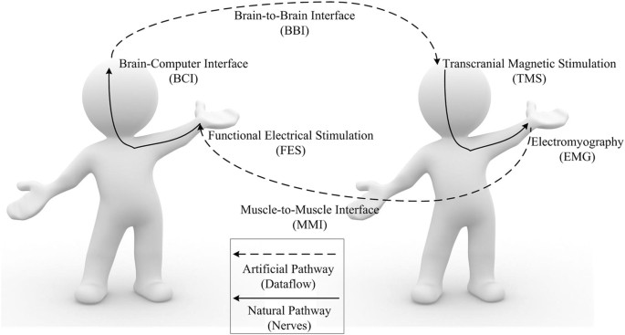
Original idea and basic terms/ acronyms of the human-to-human closed-loop control based on brain-to-brain interface and muscle-to-muscle interface.
Results
Latency and repeatability
The representative results are shown in Fig. 2(a). Brain activations are reflected by event-related de-synchronization (ERD)9, which is a normalized power attenuation in a specific frequency band (upper alpha rhythm 10–13(Hz)) with respect to a baseline time window (0.8–0.1(s) prior to the placement of cue). Motor cortical activations in form of 2-D head plots are illustrated to vividly describe the underlying mechanism of the brain and how it interacted with the mechanism. Head plots - drawn using FieldTrip, an open source MATLAB package - indicate activation spots over the brain according to electrode positioning. The majority of activations for both head plots are in the vicinity of C3 electrode over the contralateral hemispheric motor area of the right hand side. A time-frequency map of channel C3 is shown to illustrate a point to point brain activation in the contralateral hemisphere during MI task. Time-frequency plots are employed for this purpose which are plotted using EEGlab (open source MATLAB toolbox). Furthermore, sequential steps with their corresponding time delay are illustrated in Fig. 2(b). Accordingly, each loop takes 6.49 seconds in total to perform all steps (excluding rest time). Although BCI classification part had a 0.17 s delay, trigger circuitries did not introduce any detectable time delay while trigger signal transmission through the Internet showed 0.1 s latency. However, a large portion of the delay (4.5 s) corresponds to MI-BCI task and FES-evoked BCI. Despite the complexity of the mechanism design, hardware- (i.e. connections, network, circuits, processing times, etc.) and software-related (i.e. signal processing algorithm, device drivers, system software, etc.), latencies were negligible (merely 0.99 s). This fast response time corresponds to the short delay of BCI classification, EMG-triggered FES detection, and network data transfers which were approximately 0.17 s, 0.35 s, and 0.1 s, respectively. The interface between BBI and MMI was established using natural neural network connection from contralateral hemispheric motor area to index finger muscle with a trifling delay.
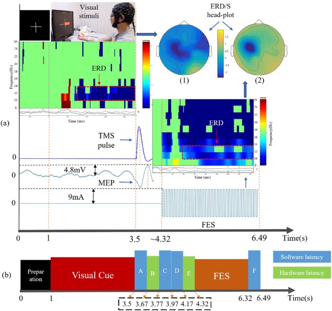
Step-by-step data flow and latency in a representative trial. (a) different steps of the experiment in detail and signals driving different devices are shown. Brain activations are illustrated by spectral power attenuation (ERD), in form of head plots and time-frequency maps, showing the location and frequency bands of cortical activations, during right hand MI and FES-evoked BCI. TMS pulse shape, induced MEP magnitude, and FES stimulation pulse are illustrated. (b) latencies for each step including preparation and visual cue appearance, A and F are EEG data classification latencies, B is trigger transfer delay via network, C is EMG classification latency, and D and E are delays for FES driver software to receive trigger and hardware to start stimulation, respectively. Physiological delays (i.e. delay of neural pathway from brain to hand muscle) were not detectable. Blue values are software related latencies. Green values are hardware-related latencies.
Additionally, automatic control loop applied to a representative pair (pair 6), demonstrated the two subjects successfully completed 85 loops without any break upon just one time motor imagery initiated by the subject in side A, which conclusively confirms the repeatability of the mechanism.
System performance
For right-hand true detection, the accuracy is calculated with the number of successful detections to the number of visual cues instructing the same hand motion imagination. Each session consists of 30 trials, among which half trials visual cue is on the right and half on the left. Figure 3(a) illustrates overall independent response accuracy (RA) for 4 sessions (120 trials) of the experiment for each pair. Each loop is categorized into four independent steps and a dependent step of human-controlled paradigm. Accuracy for each step is calculated by:
(1)
where the number of trials with a true response for a specific step is NTT and the number of related trials in each step is N RT . Here dependent RA corresponds to responses recorded for each step with respect to the prior step, for instance, the accuracy for BCI-triggered TMS detection is calculated with respect to the number of true right-hand motor imagery classification, therefore, we call aforementioned accuracies dependent accuracy. Meanwhile, independent RA is defined to show the efficiency of each individual step without any respect to its previous step. Since the number of visual cues on the right and left in each session is equal, the number of related trials for dependent BCI is 30 and for the rest of steps is 15. Dependent RA for each pair is shown in Fig. 3(a). As depicted from the figure, pair 5 has the best mean RA (80%) while the value of pair 3 is the worst (53%). Meanwhile, the highest RA reaches as high as 93%, occurred in the 3rd session of pair 5. Step-wise accuracies for each pair (Fig. 3(b)) are obtained, according to the results, MMI showed superior outcome to BBI for all pairs.
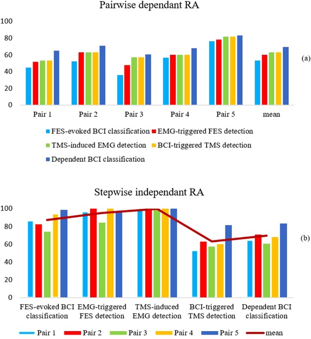
Response accuracy corresponding to each pair illustrated in form of accuracies. All accuracies are the average values through 120 trials for each pair. (a) Pairwise accuracies are calculated with respect to the prior step. In this experiment, the performance of each step is absolutely dependent on the previous one. (b) Step-wise accuracies for each pair are calculated without respect to prior step to illustrate the difference between MMI and BBI part.
The overall RA is 69.7 ± 8.55% and 87.37 ± 9.7% for BBI and MMI segments, respectively, which suggests muscle to muscle interface with the current mechanism is more reliable and accurate than the current BBI mechanism. The total response rate of the mechanism over 20 session shows 85.7 ± 12.13% accuracy. Notably, the accuracy of TMS-induced EMG detection is always 100%, owing to the fact that whenever right-hand motor imagery detection is true, a trigger is sent to TMS. The same situation is valid for EMG-triggered FES detections. The difference between pairs mostly depends on hand motor imagery and passive movement induced by FES classification accuracy. The rest of the system is properly operating which is in the prospect of a reliable BBI and MMI system. Overall RA of FES-induced BCI classification in the offline analysis have the average of 84.5% while for motor imagery classification is 63% totally (for stop and start commands). Conclusively, the overall FES-induced BCI classification accuracy was higher than motor imagery.
Analysis of variance
The Independency Ratio (IR) is defined between 0 and 1, as an indication measure for each step individually, regardless of the performance of prior step. IR can be calculated with the following equation:
(2)
Considering the hierarchy of steps, efficiency of each step independently without the influence of previous one needs to be calculated separately. To address this, analysis of variance (ANOVA) of independency ratio over different steps using results from 20 sessions of the experiment is conducted. Stepwise ANOVA yields a p-value of 0.00025 which is dramatically smaller than the level of significance (alpha = 0.05). Thus, the null hypothesis, namely “the efficiency of each step is based on chance”, is rejected and results are statistically significant (F-value 5.908). The first step was excluded from IR assessment, since its independent accuracy is unconditionally pertinent to subject-related BCI performance, rather than system performance. Therefore, calculations started from second step, which illustrated IR = 0.87 ± 0.12 with 0.015 variance, while the third step perfectly completed without any misses (IR = 1). Meanwhile, fourth and fifth steps, demonstrated IR = 0.97 ± 0.06 with 0.003 variance and IR = 0.878 ± 0.13 with 0.01 variance, respectively. Hence, individual steps functioned efficiently.
Receiver operating characteristics
To better quantify the system performance, the receiver operating characteristics (ROC) curve is drawn for each pair in Fig. 4. The efficacy of each step of this experiment is depicted using True Positive Rate (TPR) and False Positive Rate (FPR)10. Thus, some measures are defined. True Positive (TP) is true command sent to the receiver and true movement detected; False negative (FN) is true command sent to the receiver but false movement detected; False Positive (FP) is false command sent to the receiver but true movement detected; True negative (TN) is false command sent to the receiver and false movement detected. It is noteworthy that the mentioned values have been calculated solely regardless of prior steps. The accuracy of the test depends on how well the test separates the group being tested into detected and not detected trials. Accuracy is measured by calculating the area under the ROC curve (AUC). The closeness of the curve to the top-left corner of the ROC chart depicts superior performance. This figure gives a good comparison between control session and experimental sessions, with step-wise contrast. The lowest efficacy in all stages of the experiment is 0.6 of full AUC corresponding to step 2 of pair 3, which is higher than the area of control experiment (0.5). Although the largest area under the curve is 1, the best MMI + BBI efficacy is related to pair 5 with overall 0.94 ± 0.08 of AUC. Step-wise analysis illustrates that step 3 with 1.0, step 4 with 0.977 ± 0.028, step 5 with 0.924 ± 0.044, and step 2 with 0.68 ± 0.09 of AUC present best to worst performances, respectively. Conclusively, test experiments for all pairs had a larger AUC than control ones, which is expected from a working system.
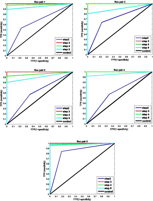
ROC curves related to step 2 (BCI-triggered TMS detection), step 3 (EMG-triggered FES detection), and step 5 (FES-evoked BCI) plotted for each pair according to their TPR and FPR values. Blue, red, and green lines are test experiment results of steps 1 to 3, respectively, while the black line is control result.
Mutual information transfer
Mutual information11, as an efficiency indicator of information transferred between two subjects, is carried out to evaluate the performance of the current system. The amount of mutual information transferred is calculated by multiplying response vector I(A, B) with the number of related trials. Here, the whole system is disassembled into two parts. In the first part, we obtained the mutual information transferred from the subject’s brain (side A) to the other subject’s muscle (side B), as illustrated in Table 1. The results demonstrate that the average information transferred via brain to brain to muscle varies between 18.82 ± 7.99 bits for pair 3 and 26.62 ± 4.432 bits for pair 5. Moreover, for the second part, mutual information transferred from the subject’s muscle (side B) back to the subject’s brain (side A) are determined and shown in Table 2. According to this table, information transferred in the remaining chain via brain to brain to muscle vary from 9.22 ± 1.27 bits for pair 1 to 10.82 ± 2.73 bits for pair 5. Even though there is common inter-subject variability for BCI dependent step, remaining steps are perceived to work reliably. In previous results, it is indicated that MMI shows a better performance than BBI, however, less mutual information is transferred through MMI herein. This occurrence is basically due to sequential nature of the mechanism which allows only those trials with a prosperous BBI to reach MMI section, which means half of the trials are related to the second part. Thus, with respect to the linear correlation between the transferable amount of mutual information and number of trials, less information can be transferred in MMI to brain section. Accordingly, there is no contradiction between results.
Discussion
A novel and distinguishing communication method based on BBI and MMI is demonstrated herein. Our current results indicate the possibility of functionally combining natural and artificial neural pathways to establish a novel communication path. It has two sections, first, from one person’s brain towards another person’s brain and muscle, second, from one person’s brain to their own hand. This is accomplished by merely using noninvasive technologies with short latency and reliably working mechanism. In other words, the goal was to establish a composite neural pathway using human natural and BCI-based artificial neural pathway to transmit commands from a sender’s brain to his muscle. To this end, cortical activations decoded from EEG and muscle movements detected from EMG signal were used as inputs, while FES and TMS were used as outputs of the artificial neural system. Experimental outcomes showed up to 85% of mean system RA achieved and totally 37.44 ± 2.5 bits of mutual information transferred. Furthermore, mean IR of steps 2 to 5 is 0.96 ± 0.08 and 0.99 s delay, explicitly reveals the system reliability and relatively fast response time of different steps of the mechanism. The proposed system may provide interesting entertainment between two individuals. To our knowledge, intending to make a move and use natural neural pathway possessed by another person to induce movement command in the first person’s muscle is not investigated in any previous research work. The novel paradigm introduced in this paper proposes a new human-to-human communication way which engages human brain and muscles. A promising capability of this mechanism is the interaction between two subjects from any distance, using the Internet as a part of the artificial neural pathway. In this way, simultaneous learning of two or more persons who are far apart is conceivable. Although analogous works focused on BBI or MMI alone have been accomplished, the full interaction between two subjects has never been addressed in any previous works in the field. Our results suggest that the proposed procedure of the mechanism is performing satisfactorily. Thus, the current design of combining artificial and neural pathways to unconventionally communicate two persons is adequately sufficient and can be subject to find operational applications.
A substantial objective of the BCI-based research is literally for rehabilitation. In addition to its entertainment application, currently proposed system can be used fundamentally for rehabilitation. Four well-known technologies used in this system, BCI, TMS, EMG, and FES are popular rehabilitation technologies. In former studies, the four employed technologies are widely used independently. Some researchers have attempted to combine two technologies among them for rehabilitation. For instance, BCI have been combined with FES12 and TMS13. Additionally, MI-based BCI has been proven to effectively improve motor recovery14. BCI can decode the motion intention and control related devices, in this case, the patients are in a rather active role in the rehabilitation process. It might potentially enhance the rehabilitation of stroke-related motor impairments by promoting neuroplasticity and altering motor cortical areas. Therefore, rehabilitation is likely to be remarkably improved15. Our proposed method initially combined all the four methods in a closed-loop system. The two subjects in side A and side B can exchange and experience all the four kinds of rehabilitation technologies. Majority of current rehabilitation procedures are performed solely on a single patient, but our research can engage two patients to realize co-rehabilitation as double players in a game. The co-rehabilitation could be designed as a competitive way, which means both patients in side A and side B are able to start or stop the rehabilitation process. They can compare “who win or who lose”. They can also exchange their roles in side A and side B to play again. They may have strong desire to win, so the rehabilitation would be performed more enthusiastically. In such a way, the co-rehabilitation may become more attractive and interesting for the patients. In this work, a combination of BBI and MMI is accomplished to illustrate the possibility and applicability of this kind of rehabilitation, which is based on the reciprocal human to human interaction channel.
According to results, FES-evoked BCI demonstrated higher cortical activity within the demanded frequency bands (i.e. alpha and beta rhythm) compared to MI-based BCI as indicated by ERD plots depicted in Fig. 2(a) and FES-evoked BCI classification accuracy. This phenomenon might rely on the effect of FES-generated sensory feedback, which activates cerebellum and increases its interaction with cortex. Electrical stimulation of motor nerve fibers may generate both orthodromic and antidromic impulse. An impulse can cause depolarization of horn cells which leads to conductivity increase between pyramidal tract axons and anterior horn cells. Therefore, FES can induce changes in the segmental level even in people with lesioned limb and capable of activating anterior horn cell repeatedly which leads to enhancement in the corticospinal excitability compared to MI alone16.
The present work is a pilot study which has some limitations and there is a vast room for future development. Although noninvasive signal acquisition and stimulation methods employed in this paper are easy to implement and portable, their inherent shortcomings restrict further development of the mechanism. For instance, assessment of different natural neural pathway (i.e. lower limb motor nerves, etc.) effect is barely practicable. In addition, according to network based brain activations, for a perfect BBI all activated cortical spots in the brain of the subject in side A should be stimulated in the brain of subject in side B with corresponding latencies. However, it is impractical to stimulate different spots using a single TMS coil with low latency or using several TMS coils for neighboring spots. This is due to the size of the coil which prevents the reachability to certain regions that are spatially close to each other. Therefore, merely the physical response of the motor unit was used to determine which brain area to be excited. Moreover, only alpha and beta frequency bands are used to determine brain activations. This is mostly based on low signal to noise ratio of EEG signal which limits usability of features in other frequency bands (i.e. gamma band). Hence, noninvasive methods are replaceable with more accurate invasive technologies, i.e. Electrocorticography (ECoG), to accomplish a real task consisting of complex movements. Furthermore, implementation of the mechanism is technically complicated, this may pragmatically cause technical deficits while putting it into real-world application. Furthermore, simultaneous FES stimulation and MI suggested for maximizing short term neuroplastic effects17, while in our study they have been performed separately, which may be subject to modification in future rehabilitation practices.
Current software and hardware infrastructure is capable of being adopted for more than two healthy or disabled subjects to have interaction (e.g. social communication) with each other. Therefore, co-rehabilitation between two or more paralyzed patients simultaneously using the proposed mechanism can be further investigated. Besides, the response rate of the mechanism was directly interdependent to BCI performance. Thus, advanced sensorimotor pattern extraction algorithms to enhance the performance of the system and fundamental research on the exploration of the brain network that will provide more and effective control modes for BCI, are still in high demand. The current system design is one out of many possibilities. For instance, a possible substitution for BCI part is online ERD calculation. In this case, instead of using left or right hand EEG signal classification, attenuation or increase of ERD value in electrodes neighboring motor area can be used as BCI output and generate a trigger for TMS. Accordingly, TMS stimulation intensity could linearly be adapted with ERD value, meaning higher ERD value cause higher TMS stimulation intensity and vice versa. As a result, the amplitude of detected MEP will change linearly with TMS-induced movement, and accordingly, the FES stimulation may be modified and applies higher or lower stimulation intensity regarding MEP amplitude. Under this circumstance, both subjects will not only stop or start the mechanism but also control the range of movements which enhance the interaction level between two subjects.
Methods
Overview
The implementation framework of BBI and MMI for human-to-human closed-loop control is shown in Fig. 5. In side A, we used a commercial device (SynAmp, Neuroscan, USA) for EEG measurement and a commercial device (REHASTIM 2, Hasomed, Germany) for FES. In side B, we used a commercial device (Rapid 2, Magstim, UK) for TMS, and a custom-made device (iMYO, SJTU, China) manufactured in biomechatronics and bio-robotics laboratory for EMG detection.
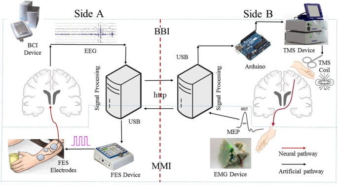
System implementation. Different steps of the mechanism, employed devices, connections and data flow direction is illustrated.
The proposed method consists of five main steps. First, the subject in side A uses motor imagery (MI, right or left hand motion) to start or stop the control (the first step: MI-based BCI classification). Afterwards, in the case that a required classification result is generated (i.e. right hand MI), a square pulse (5 V, 1000 ms) will be triggered as a handler of computer-to-brain interface (CBI) from an open-source electronic I/O board (Arduino, Sparkfun Electronics, Boulder, CO), subsequently initiates the operation of TMS device to non-invasively stimulate primary motor cortex of a subject in side B (the second step: BCI-triggered TMS). In the meantime, raw EMG data are collected and transmitted via Bluetooth 4.0 USB module to a desktop PC in side B, where runs a designated software (C#, Microsoft visual studio, USA) for EMG analysis, as a result of TMS, hand motion of the subject in side B may be elicited and in consequence will carry out a significant change in motor evoked potentials (MEP) compared to a threshold (the third step: TMS-induced EMG detection). MEP detection of hand movement will result in generation of a trigger signal and the signal will be sent to PC in side A via Internet connection (HTTP protocol), hence starting muscle stimulation on the subject in side A using a self-designated software coupled with FES device through USB connection (the fourth step: EMG-triggered FES detection). Finally, FES-generated hand motion may evoke changes on EEG signal which are detected via BCI system (the fifth step: FES-evoked BCI).
Participants
This study was approved by local ethics committee of Shanghai Jiao Tong University. All experiments were performed in accordance with relevant guidelines and regulations. Twelve healthy subjects (age 23 ± 3 years old, all males), deprived of any disclosed background of central or peripheral nervous disease, voluntarily participated in this study (Table 2). All participants were naive to BCI and TMS operations. They were fully informed about the entire experimental procedure, the potential risks/benefits, and possibility of publishing their identifying information/images and thereupon given the written consents before the experiments. During the experiment, each subject in a pair played two roles, sender and receiver. Since the architecture of closed-loop system required the sender who sends command for BBI chain was also a receiver of MMI chain, and on the contrary, the receiver of BBI was also the sender of MMI chain.
Brain-Computer Interface
BCI experiments were performed in an electromagnetic shielding chamber, which is designed for noise-sensitive experiments like EEG recording. The subject in side A wore an easy-cap of 64-channel Ag–AgCl electrodes (1 cm in diameter), with a right ear reference positioned on temporal bone and a ground electrode placed on the forehead next to front parietal. The electrodes were placed according to the international 10–20 system. All channels in the vicinity of the motor region on both hemispheres were used (C4, C2, CP4, C6, FC4, CZ, C1, C3, FC3, C5, and CP3). All impedances were kept below 5 kΩ throughout the experimental session. The signals were digitized at 250 Hz using a bio-signal amplifier (SynAmp, NeuroScan Inc, USA). The subject assigned to side A as a sender for BBI was seated in a comfortable chair and asked to put both the hands on the table in front of a PC display. They were instructed to do left or right-hand motor imagery (wrist flexion imagination) successively according to placement of a red rectangle cue as visual stimuli on the screen. Acquired raw EEG data were filtered using a 2nd-order infinite impulse response (IRR) Butterworth band-pass filter to the target frequency band (8–26 Hz) which covered the entire alpha and beta band as well as mu rhythm. Afterward, EEG features were extracted using common spatial patterns (CSP) method18. Extracted features were classified by the fisher’s Linear Discriminant Analysis (LDA) method19. Aforementioned algorithms are explained in details (Appendix A). A self-developed computer software in visual studio C++ (Microsoft Visual Studio, USA) was programmed to collect EEG data and sent it to a corresponding MATLAB code module (Mathworks, Natick, MA) simultaneously to automatically perform classification. The classified result was compared with the placement of visual cue, and the number of correctly classified trials was returned and shown on the screen.
Transcranial Magnetic Stimulation
TMS and repetitive TMS (rTMS) are non-invasive methods used to induce excitability changes in the motor cortex via a wire coil generating a magnetic field that passes through the scalp20. TMS is a technique that can non-invasively excite a specific population of cortical neurons with a spatial resolution of millimeters and a temporal resolution of microseconds21. Prior to performing the stimulation, an evaluation procedure was defined to optimally recognize the position of hand motor area on the contralateral hemisphere, M1 area on the scalp, which took approximately 10 minutes. Two participants were discarded from formal experiments and further analysis due to their unrecognizable hand motion response. Along the evaluation session, the subject in side B was accommodated on a comfortable chair specifically designed for fixating participant’s head handled by a mechanical mechanism. Head fixation was accomplished using a header stand and a forehead fasten part which can be adjusted according to each subject’s height and head size as shown in Fig. 6 (side B). TMS coil was centered tangentially over M1 hand motor area and fixed on the exact position and orientation discovered for each participant. The exact position (hot spot) for TMS over motor cortex, which connects to flexor carpi ulnaris muscle, was found manually by trial-and-error searching. Each single pulse was delivered by a double 70-mm coil (Rapid2, Magstim, UK). The stimulation intensity for each subject is expressed as a percentage of the maximum stimulation output (magnetic field strength 2.2 (Tesla) for double 70-mm coil), which were selected manually as follows regarding to each subject’s response to TMS stimulation: pair 1 (73%), Pair 2 (80%), pair 3 (75%), pair 4 (85%), pair 5 (75%), pair 6 (82%).
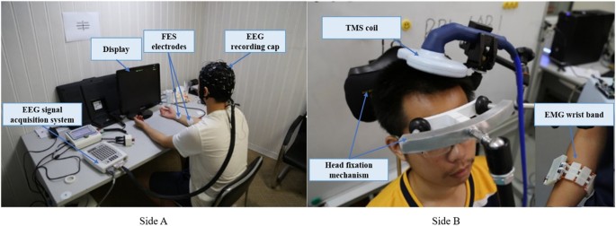
Illustration of experimental condition. The two subjects sat in two separate rooms to avoid any visual or auditory interactions. Side A: EEG equipment and FES device. Side B: Custom-designed head for TMS stimulation (the white part is soft and bouncy foam which is designed to reduce annoying tension on participant’s forehead). EMG wristband attached on the forearm shown on down-right.
Electromyography
A custom-made surface EMG sensor (iMYO, SJTU) consisting of 8 bipolar EMG channels (sampling rate 1000 Hz), designated on a soft wearable wristband as shown in Fig. 5, was used for measuring TMS-induced MEP fluctuations. Raw MEP data over flexor carpi ulnaris muscle were acquired from EMG sensor, amplified and transmitted to side B’s PC using Bluetooth communication system for further analysis. Feature extraction and classification were performed by a self-developed C# software (Microsoft visual studio). Acquired motion information was compared to a threshold value in real-time, defined as an average of MEP amplitude over 20 evaluation trials. Since insignificant changes in TMS-induced MEP were observed, the minor threshold value was picked (4–6 mV with inter-subject variability). The threshold value was optimally picked prior to the experimental session for each specific subject. The software would automatically figure out a proper motion was made in the subject’s hand, when the amplitude of four out of eight channels was evidenced to meet the threshold value and a trigger signal was sent to side A through an Internet connection (HTTP protocol).
Functional Electrical Stimulation
FES, as a well-known noninvasive muscle stimulation method, is used in this experimental design. Rehabilitation and therapeutic effects of FES on gait, motor recovery, and motor cortex activity are widely studied in the literature22. There are also numerous interesting and unexplored applications of this method for moving a body joint spontaneously by stimulating skeletal muscles for healthy persons. In side A, FES was used to generate right-hand movement (wrist flexion), which was controlled by C++ program in PC via USB port. A pair of FES electrodes with approximate 25cm 2 was attached to the subject’s forearm skin over flexor carpi ulnaris muscle, and the stimulator delivers the desired electrical stimulation pulses to the electrodes through analog connections. The subject in side A was expected to perform the hand motion when the corresponding program received the trigger from side B. In each trial, as soon as a trigger was sent to TMS from side A, the software serving for FES looked for a trigger from side B. Once the intended trigger was received from EMG command, FES started the stimulation for a preset period of 2 seconds (biphasic square signal with 9 mA amplitude, 250 μs pulse width, and 30 Hz frequency).
Experimental Protocol
Human-Controlled Loop
The participant in side A sat on a comfortable chair in front of a 17-inch display with an EEG cap mounted over sculpt and rest their both hands on a desk (Fig. 6). During each experimental session, two participants had to carry out specific tasks over sequential trials. EEG recording trials comprised of four sub-sections for subjects in side A. At the beginning of the session a blank screen was projected to the subject for 3 s indicating idle state, then a white cross fixation appeared at the center for 1 s altering the subject to get ready for the task which was going to start shortly. Afterward, a red rectangle (approximately 20*10 mm) appeared on the left or right side of the cross for 2.5 s instructing the motor imagery execution. Subjects were instructed to imagine the motion of left or right hand wrist flexion following visual stimulus orientation. Raw EEG data from this time window were instantly sent to the classifier, after 0.5 s the cross vanished and the trial terminated with 1 s of the blank screen, which was vital to remove the possibility of overlapping between varying mental states of consequent trials. Each subject underwent 5 sessions of experiment, 30 trials each (150 trials in total). Raw signals have been clipped in the time window of −1 to 3 second corresponding to the onset of the cue as time zero. Recorded EEG data during first session consisting of 30 trials were used for training. A detailed illustration of the protocol is shown in Fig. 7. Two types of BCIs (independent and dependent BCIs) were used for the subjects in side A. In the human-controlled loop, the independent BCI was motor imagery (MI) based BCI. The subject imagined the right or left hand which controlled the mechanism to start or stop, respectively. The dependent BCI was FES-evoked BCI which was irrelevant to the subject’s voluntary intention and merely used in automatic loop. The MI-based BCI and FES-evoked BCI used the same feature exaction and classification algorithms in this work. Throughout the experimental session, the subject in side B sat on a custom-designed chair in a separated room to barricade any visual or auditory interaction from the subject in side A. Subjects were asked to stay relaxed and wore earplugs to prevent hearing the click sound produced by the TMS coil. TMS-induced MEP can be detected by EMG sensor, which was used as a trigger for FES in side A. In fact, the subject in side B could also dominate the control, i.e. the voluntary wrist flexion and extension could be used as “start” or “stop” commands. For clear and concise representation, the side B-dominant control is not provided in this paper, i.e. the side B was passively involved in the loop.
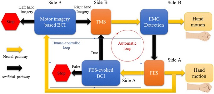
Block diagram of human-controlled loop and automatic control loop. Artificial pathways connect neural pathways of side A and side B as a closed loop.
Automatic Loop
The only difference between automatic protocol and human-controlled loop protocol was indeed the BCI part. In other words, independent BCI based on motor imagery served in the human-controlled loop, while dependent BCI based on FES-evoked EEG served in the automatic loop. FES made a muscle contraction and generated passive hand motion that could evoke EEG changes. In this case, BCI could automatically detect and classify the EEG changes. In automatic paradigm, a trial was not finished after FES generated the hand motion. Instead, if classifier’s response for FES-evoked BCI was true, a trigger would be sent to TMS as a trigger and another loop would start as exhibited in Fig. 7. This procedure continued until classification output of FES-evoked BCI, turned out to be false. This is interesting because we could observe the subject in side A had repetitive and continuous right hand movements, just by thinking about moving his hand once at the beginning. However, in the human-controlled paradigm, each trial terminated regardless of the classification result. The difference is obvious as depicted in Fig. 7. The continuity of automatic loop was extremely based upon FES-evoked BCI. In human-controlled loop paradigm, the subject could determine to continue or stop, while In automatic loop, FES would evoke changes of EEG signals and BCI could detect the changes and started next loop automatically, therefore, the action could repeat and never stop if BCI did not provide a wrong detection. The automatic control loop was only tested for pair 6 solely, as a proof of concept.
+++++++++++++++++++++++++++++++++++++++++++++++++++++++++++++++++
e - Data Communication interfaces in ADA

++++++++++++++++++++++++++++++++++++++++++++++++++++++++++++++++
entertainment systems. one another on the road to help avoid accidents, or between cars and roadside wireless communications points to dispense traffic advisories and warnings in a way that doesn’t require the driver to continuously listen to the radio or ...
Tidak ada komentar:
Posting Komentar