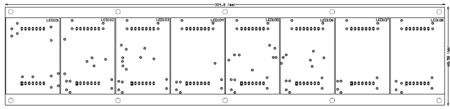
Dot matrix LED running display v2.0

Features
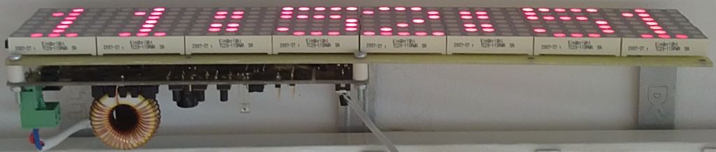
- LED matrix display 40×7;
- Display of clock, calendar, inside and outside temperature, custom text massages;
- Automatic Daylight Savings Time;
- Capability of keep the real time clock works correctly for more than one week without power supply.
- Clock automatic calibration – a software function, adding or subtracting a preset number of seconds (0-59) once time per day, improving clock accuracy;
- Inside temperature measurement (-40 ÷ +75) °C, ±0.5 °C accuracy;
- Outside temperature measurement (-40 ÷ +75) °C, ±0.5 °C accuracy;
- Displaying minimum and maximum temperatures reached;
- Supports static and running massages with different effects;
- Full Cyrillic and special symbols supports;
- External memory for 10 custom messages, freely configurable via PC software;
- Bult-in fixed messages;
- Automatic brightness control;
- IR remote control for settings and massage selection;
- Power supply: 12 ÷ 24V DC;
- Front panel dimensions 305×69 mm.
Schematic Description
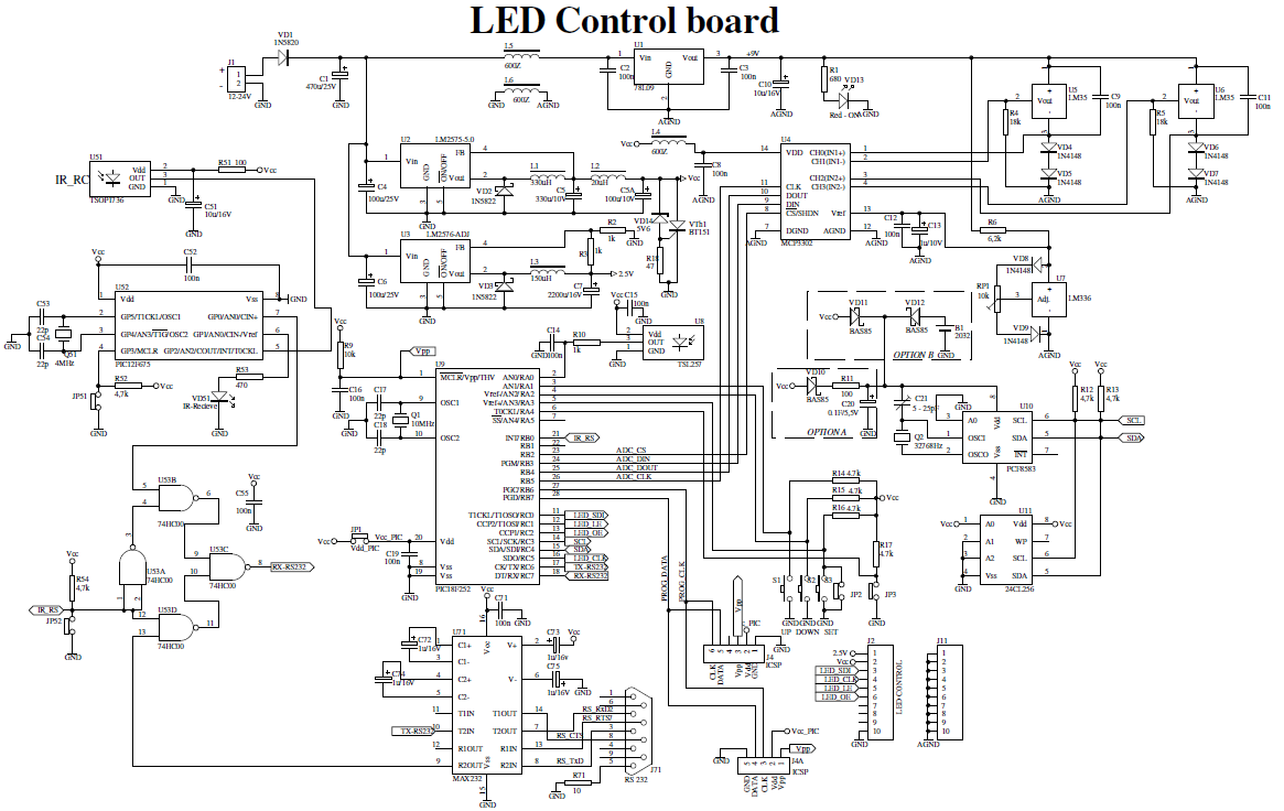
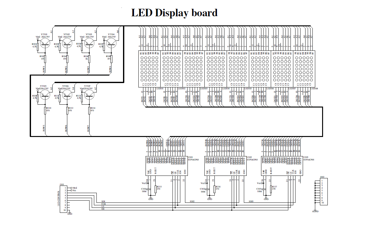
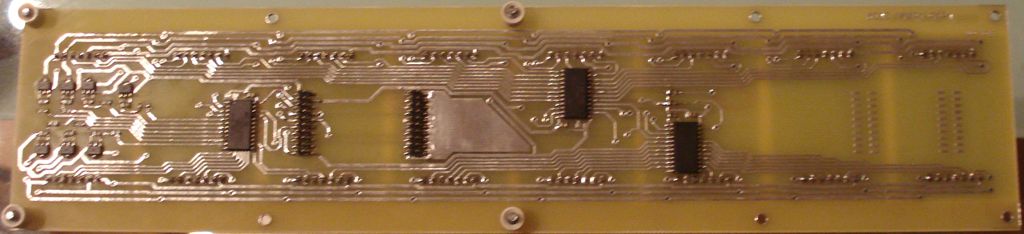
The device is separated of two parts named LED control board and LED display board. Two PCBs are designed to fit together one behind other using two sets of dual row connectors and 4 spacers. One of this connector is used for electrical connections, while the other one is used only as mechanical connecting element.
The core of the device is the microcontroller PIC18F252 (U9). The microcontroller controls all functions of device, generates the whole algorithm to control the LED matrix. LEDs are connected in matrix 40×7. The columns tie together the cathodes of LEDs’ and rows tie the LEDs’ anodes. The LEDs are dynamically controlled row by row. To safe space and number of components, the LEDs are driven with specialized LED driver STP16CP05 (U101-U103), produced from ST Microelectronics. Each one of these IC contain 16-bit serial-in, parallel-out shift register, latch register and 16 constant current output channels. Outputs are open drain type, allowing connection of a load supplied with up to 20V supply voltage. The constant current for all outputs is set from an external resistor (R115-R117) connected to pin 23. It’s value set the LED’s current from 5 to 100mA.
In this application, the three LED drivers are connected in cascade and controlled from the microcontroller over SPI protocol. The microcontroller sends a 48-bit word, controlling one row at the time. The 40 LSB represent LED states (1-On, 0-Off) in the row and controlled their cathodes. The 7 MSB are controlled the anodes through the 7 driver transistors (VT101 – VT107). The 40th bit remains unused. The microcontroller sends this 48-bit word each 1ms. There is 7 row cycles for displaying each row plus one blank cycle, used for process the temperature measurements. Therefore, the refresh rate of display is 125Hz. To control the display brightness is used the “outputs enable” (OE) pin.
Each row cycle begin with logical 0 on OE pin (outputs are enabled). Depends on the desired brightness the duration of enable signal is changed, using the microcontroller’s on-chip PWM module.
Note, that the numbers of columns and rows are not connected in sequential order to the corresponded pins of ICs (U101-U103). This is done due to simplify the design of PCB. The LEDs’ corresponded bits are rearranged by software to fit them with their physical order.
Real-time clock / calendar
The real time clock is implemented with U10 – PCF8583. This is a clock / calendar / alarm circuit with I2C interface and on-chip 32768Hz oscillator. The PCF8583 contains all necessary counter registers to provide real time clock and date information. Its power consumption is very low (typical supply current is 10 A) and operate in wide range of supply voltage from 1 to 6V. These features give a possibility to supply the real-time clock for a long time using a small lithium battery or even with a back-up capacitor. Both options are available in the designed PCB. The footprint for lithium battery is suited for 2032 type socket.
The experiments using 1F back-up capacitor shows that the clock remain active more than a week after turning-off the power supply. The diodes VD10, VD11 and VD12 should be Shotkey type as shown in the schematic, due to their low drop forward voltage. Trimmer-capacitor C21 is used to adjust the oscillator frequency at 32768Hz. For I2C communication is used the Master Synchronous Serial Port (MSSP) module in PIC18F252. This module is set in I2C master mode. On the same bus an external EEPROM (U11) can be connected to expand capacity of data storage.
Note, that the numbers of columns and rows are not connected in sequential order to the corresponded pins of ICs (U101-U103). This is done due to simplify the design of PCB. The LEDs’ corresponded bits are rearranged by software to fit them with their physical order.
Note, that the numbers of columns and rows are not connected in sequential order to the corresponded pins of ICs (U101-U103). This is done due to simplify the design of PCB. The LEDs’ corresponded bits are rearranged by software to fit them with their physical order.
External EEPROM
On the same I2C bus an external EEPROM (U11) can be inserted to allow storage of custom messages. This is a standard serial EEPROM (32K x 8) type 24LC256 or some equivalent. Firmware is written on that way that the device can work without this EEPROM. In this case the display will show only built-in messages.
Temperature measurement
For ambient temperature measurement are used LM35 sensors (U5, U6). They are factory calibrated directly in ° Celsius. The output response is 10mV/°C. The supply voltage should be between 4 and 30 Volts. To make a full-range temperature measurement, a negative voltage must be applied to the output through a resistor (R4 and R5). To ensure this requirement, the ground pins of the sensors is connected to the analog ground through two diodes (VD4,VD5 and VD6,VD7), which pick them up with approximately 1,4V. In that case the Vcc (+5V) power supply is not enough for LM35, so additional voltage regulator is need it to use – U1 (78L09).
The signal from sensor is taken between the output and negative pins of LM35. The voltage between these two pins is bipolar with polarity dependent on the measured temperature sign. The sensors could be connected with external three-wire cables. Software is designed to show inside temperature from U6 and outside temperature from U5.
A/D converter
Both LM35’s outputs are connected to U4 – MCP3302. This is a Successive Approximation Register (SAR) analog to digital converter. It provides 13 bits resolution (12 bits plus one sign bit). The MCP3302 has 4 analog inputs, which can be configured either as 4 single ended or as 2 differential inputs. The application requires 2 differential inputs to convert both bipolar voltages from the LM35 temperature sensors. As a reference voltage is used U7 – LM336-2,5. It’s output value need to be adjusted at 2,55V using trimmer-potentiometer RP1. VD8 and VD9 are used for temperature compensation.
The MCP3302 has an SPI interface, using four signal lines. These lines are under software control from the microcontroller (U9). To ensure accuracy analog ground is separated from the digital using small ferrite beam (L6). This is an SMD type Z600 ferrite beam in 0805 package. The same type are used to decouple the power supply for A/D converter and for temperature sensors and reference voltage (L4 and L5 respectively).
To increase the accuracy and stability of the indication, a modified average filter is applied. The microcontroller get samples from temperature measurements on each second and the values are stored in a buffer. When 10 measurements are stored, microcontroller subtracts the highest two and the lowest two values. From remain six values is calculated an average sum. Then to stabilize the display reading, a slight deadband is applied to the average sum.
Brightness control
For an automatic brightness control is used U8 (TSL257) – light-to-voltage converter. Its output voltage is directly proportional to light intensity on the built in photodiode. The voltage from the light sensor is measured using an on chip microcontroller’s ADC. The result influences to the PWM module from where the LED panel is changed its brightness. To avoid unwanted blinks of display, a slight software delay of PWM control is applied.
IR remote control
An additional feature of device is the possibility to be controlled using an Infrared remote control. It allows device to be installed on a place with difficult access. The decoder is implemented with microcontroller PIC12F675 (U52) and designed to work with a standard TV remote control, matching RC5 protocol. This protocol is supported from TV Philips. The decoder received a demodulated digital signal from IR receiver TSOP1736.
The software decodes the received command and transmits it to the main microcontroller U9 over an asynchronous serial connection. The LED VD51 is blink once on each recognized command. The main microcontroller (PIC18F252) receives commands from IR decoder using its hardware Universal Synchronous Asynchronous Receiver Transmitter (USART) module. Because the same module is also used for RS232 connection to the PC, RXe signal is multiplexed between the U52 output or U71 (MAX232) output. The switch is realized with 4 NAND elements in U53 (74HC00).
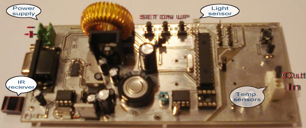
Power supply
The device is needed of three different stabilized supply voltages: Vcc (+5V) for main part of schematic, Vled (+2,5V) for LEDs’ anodes and a +9V for temperature sensors. For highefficiancy Vcc (+5V) and Vled (+2,5V) are provided using a step-down regulator. For a +5V is used U2 (LM2575-5.0) and for Vled is used U3 (LM2576-ADJ). Because of low consumption from the +9V it is implemented with low power version of standard linear regulator 78L09. Vth1, VD14 and R18 realized overvoltage protection. If the voltage of Vcc exceed the zener diode voltage plus thyristor gate voltage the thyristor starts to open and gives short circuit Vcc to ground. This protects all of integrated circuits from accidentally raising the supply voltage. Note, that the external power supply must have a fuse or current limiter. Of course, this protection circuit is not necessary, but strongly recommended, especially in the stage of testing. Other two power supplies are not so critical if the voltage is increased. The LED drivers’ outputs can work with up to 20V load and limits the current through the LEDs. The ICs LM35 and LM336 also can work with higher than 9V power supply.
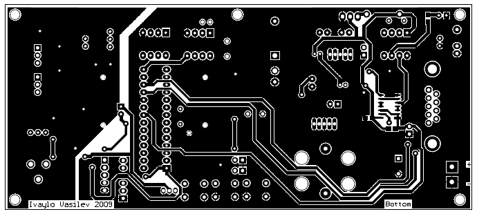
It is necessary to pay attention to the Vled voltage. Its value is very important due to the power dissipation from the LED drivers. In this case are used super bright red LEDs dot matrix modules 5×7 (TC20-11SRWA). The LED forward voltage Vf is 1,85V at 20mA. It’s not a problem to use other types of LEDs. For reliable work the Vled should be 0,5-0,7 higher than the Vf. But not to be much more higher, because the power dissipation from the drivers will increase and a thermal shut-down protection will be activated. To calculate the Vled use the next formula:
where R2 is between 1 and 5 k .
It is also need to choose a proper value for LEDs current. The current is set with R115, R116 and R117 resistors, connected to pin 23 (R EXT) of LED driver. The showed value (270 ) set the current at approximately 80mA per output. Because the duty cycle of each row is 1/8, the average current through the LED is 10mA. See the STP16CP05 datasheet for output current resistor set. For convenience of changing these resistors, the footprints of R115 and R116 are duplicated next to R117, named R115’ and R116’.
Display functions
The display settings are adjusted from the user with three local buttons S1-S3 or by Philips TV compatible IR remote control. The meaning of the local buttons are as follows: S1 – UP; S2 – DOWN; S3 – SET. The available buttons from IR remote control are as follows:
- PROG UP: equivalent to local S1 (UP),
- PROG DOWN: equivalent to local S2 (DOWN),
- MENU or MUTE: equivalent to local S3 (SET),
- 0 … 9 – directly select messages,
- VOL UP, VOL DOWN: Move cursor in Clock settings mode forward or backward respectively.
After Power on the display enters in normal mode of operation, showing continuously the last selected message. The values for temperatures are unavailable for the first 10 seconds. Instead of temperature the display will show “F -.–“. If this message is shown after this period, it is an indication for a fault temperature sensor.
To select other message press directly one of digital buttons (0 … 9) on IR remote control, or press one time SET, select the message number using UP/DOWN buttons or digital buttons and press again SET. If an external EEPROM is placed on the PCB and a valid message is written to selected corresponded number the display will show it. If an external EEPROM not installed or the selected number is empty or deleted the display will load a message from built-in memory. Note, that to use the external EEPROM, the setting in the Service menu (extEEP), must set to Y (enable).
To show MAX/MIN temperatures during normal mode of operation press UP or DOWN buttons. At first time the display will show Maximum or Minimum reached Outside temperature. To show MAX/MIN inside temperatures, press UP or DOWN buttons for the second time (no later than 5 seconds). Each time you press two times the same button UP or DOWN the display switched between Inside and Outside values. In five seconds the display will return in normal mode of operation. To reset values manually, while in MAX/MIN mode press SET button. A confirmation message “RESET?: ” appeared. Using the buttons UP/DOWN select Y (Yes) to confirm or N (No) to reject and press SET. Note, that MAX/MIN temperature function is not available for the first 30 seconds after power on.
Configuration menu
In normal mode of operation press two times SET button. A “Config” is appeared on display. Using UP button the display shows the following options: Time -> Bright -> °Reset -> PC conn. -> back. The button DOWN walks through the same options in reverse order. To return in normal mode select press SET button when “back” or “Config” label is showed. If none of buttons is pressed for more than 10 seconds, display will automatically return in normal mode.
-Time: Press SET to enter in set Time and Date mode. Display shows clock and tens of hours are flashing. Set the value using the digital buttons (0 … 9) from IR remote control. After entering the value, the display automatically selects the ones of hours. In the same way successively enter values for minutes, day, month and year. The day of the week is calculated automatically. Alternatively, the values can be set using UP/DOWN buttons and button SET to switch to the next step. To skip the steps forward and backward use buttons VOL UP and VOL DOWN from IR remote control only. To exit from Time and Date settings mode without changes, press repeatedly VOL DOWN until “Time” label appeared.
After entering the value for years press SET button to enter in mode of confirmation the new clock value. The new time and flashing “OK” is displayed. When the button SET is pressed again the new value of clock and date will apply, the seconds set to :00. If an incorrect value was entered, press UP button to return in begins. To discard all changes and return to configuration menu, press DOWN button.
-Bright: Press SET to enter in set Bright mode. Display shows “Bright” and a digit for bright degree from 1 (minimum) to 8 (maximum) or A for automatic mode. To select a new value for the bright use buttons UP and DOWN to set one of eight degrees or auto mode. From the IR remote control the values can set directly with digital button (1 … 8) or 0 for auto mode. Press SET again to exit and return to normal mode. The bright setting is stored into built-in EEPROM.
-Reset: This setting switches between automatic or manual mode of reset MIN/MAX temperature registers. When “°Reset A” is showed on display the registers for MIN/MAX temperature reached are reset on every day at 00:00. When “°Reset M” is showed on display – MIN/MAX registers are reset only manually. To switch between auto/manual modes press SET. The setting is stored into built-in EEPROM.
-PC Conn.: Use this option to connect the display to a PC via RS232. The Message Editor can operate with display only in PC connection mode. When “PC Conn.” is selected, press a SET button. A confirmation message “Contin?N” is shown, asking are you sure to continue entering in PC mode. Use buttons UP and DOWN to select “Y” to confirm or “N” to exit from this function. If you select Y and then press SET, the display will enter in PC mode and RS232 connection will activated. Once you entered in PC mode the IR remote control is deactivated. To return in normal mode of operation and activate the IR remote control you have three options: press a local button SET, click on Disconnect button in Message Editor software or
restart the device. During this mode of operation a message “PC mode” is shown permanently on display. During read and write operations the display may start blinking for a short time.
restart the device. During this mode of operation a message “PC mode” is shown permanently on display. During read and write operations the display may start blinking for a short time.
Message Editor Software. First ensure that the display is in PC mode of operation. From drop down menu select a COM port to which cable or USB to RS232 converter is connected. Click on Connect/Test button. If everything is OK, software shows a message “The display is connected” and display controls become active. If an error message occurs “The display is not responding” check all conditions mentioned above and try again. Only messages from external EEPROM can be read and modified. Each operation of read, write and delete message is applied to the selected message only. Upload button is read the selected message from an external EEPROM and put it in Message section. Download button sent a prepared message to display’s EEPROM. A Delete button deactivate selected message. The content of message remains in memory, but marked as deleted. This means that the display will show a message from built-in flash memory, not from external EEPROM. To activate the same message again,
upload and then download it. To construct a new message sequence showing different data and effects, use drop down menus, from where you can add a message text and commands. The maximum length of message is 250 characters, which includes all symbols and commands. Configured message can be stored to a text file with *.msg extension.
upload and then download it. To construct a new message sequence showing different data and effects, use drop down menus, from where you can add a message text and commands. The maximum length of message is 250 characters, which includes all symbols and commands. Configured message can be stored to a text file with *.msg extension.
Service menu
Service menu is useful during the initial start-up and testing the device. To enter in service mode press and hold local buttons S1 and S3 until “Service” text is displayed. Alternatively from IR remote control: in Config mode, press Power/Stand By button. To return in normal mode press SET button while the display shows “Service”. Use UP or DOWN buttons to select one of test functions: ASCII, external EEPROM, RTC auto correction, Light sensor, PWM output, ADC channel 1, ADC channel 2, IR commands, Firmware version.
-ASCII: Shows display representations for whole ASCII table. Press SET to enter in this mode. The display shows for example “ 4A (J)” – a hexadecimal address and corresponding ASCII symbol in brackets. Use UP/DOWN buttons to scroll through the all addresses. To exit from this function press SET.
-External EEPROM: This function is used to enable (Y) or disable (N) the external (I2C) EEPROM. In this mode press SET button to alternate the setting: “extEEP:Y” or “extEEP:N”. If the external EEPROM is disabled the display will show only bult-in messages nevertheless, that in EEPROM is written an active message. This setting is stored in built-in EEPROM.
-RTC auto correction: This function will add or subtract a preset amount of seconds at 4:30 am every day. This will automatically correct the time corresponding on how many seconds the real time clock is run fast or slow per 24 hours period of time. To set the correction value press SET button. With UP and DOWN buttons set the value from -59 to +59 seconds. To disable this function set 0. The selected value is written in built-in EEPROM.
-Light sensor: Shows two values: A – a row ADC value (8-bit, integer) read directly a voltage from Light sensor, F – a filtered value from Light sensor.
-PWM Output: Shows the actual pulse width value (8-bit integer) controlling the bright of LEDs. The value 0 is corresponding to maximum bright, while the value 200 is corresponding to minimum.
-ADC channel 1: Shows the 16-bit signed integer value read from external ADC, differential channel 1. This channel is connected to an outside temperature sensor. On the left side a letter “o” is showed with an index from 0 to 9. This is the input buffer memory index. Press SET to switch showing a filtered value (integer with sign before converted in Celsius degrees).
-ADC channel 2: The same as ADC channel 1 for inside temperature sensor.
-IR commands: Shows for a short time a decoded command from IR remote control unit. This is a converted command from U52 (PIC12F675), not directly read from IR remote control.
-Firmware version: Shows current firmware version loaded in PIC18F252.
In conclusion
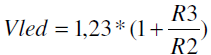
To start the schematic are not required any special adjustments. If the device is assembled properly and two microcontrollers are programmed it will run right away. U9 can be programming with one of two available connector J4 or J4A, depending on the programmer type. It is possible need to disconnect the Vcc from U9, during programming. For that purpose is provided JP1. The U52 must be program externally. Some programming tools may require do not put capacitor between MCLR pin and ground (C16). Note, that the two double row connectors connected the two boards are SMD type. The clearance between the pins is 2,00mm not 2,54! The jumpers JP2, JP3, JP51, JP52 are reserved for some test functions and no needed to be installed. This is a demonstration device. I am open to any ideas and issues concerning the project.
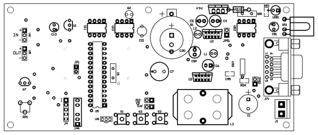
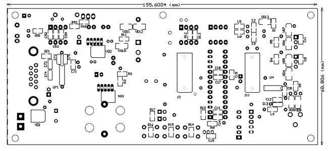
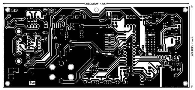
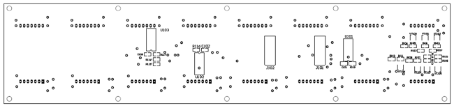
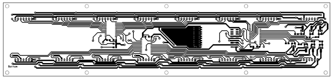
PCB

XXX . XXX How Remote Controls Work
In this article, we'll examine the infrared technology used in most home theaters, look at the difference between IR and RF remotes, find out the difference between a "universal" and a "learning" remote and check out some of the other high-tech features you can find on remotes today, like PC connectivity, RF extenders and macro commands.
Infrared Remote Controls: Inside
An IR remote control (the transmitter) sends out pulses of infrared light that represent specific binary codes. These binary codes correspond to commands, such as Power On/Off and Volume Up. The IR receiver in the TV, stereo or other device decodes the pulses of light into the binary data (ones and zeroes) that the device's microprocessor can understand. The microprocessor then carries out the corresponding command.


To get a better idea of how the process works, let's take a look inside a typical remote control -- the universal remote that came with the author's digital cable box. The basic parts involved in sending an IR signal include:
- Buttons
- Integrated circuit
- Button contacts
- Light-emitting diode (LED)


To find out more about the parts on a remote-control circuit board, check out Inside a TV Remote Control.
On the component side, the infrared receiver sits on the front of the device where it can easily see the signal coming from the remote control.
You've probably noticed that some remotes only work when you're pointing them directly at the receiver on the controlled device, while others work when you're pointing them in the general vicinity of the receiver. This has to do with the strength of the transmitting LED. A remote with more than one LED and/or a particularly powerful LED produces a stronger, broader signal.
Now let's find out how these parts work together to allow pulses of light to change the channel on a cable box.
Infrared Remote Controls: The Process

Sony TV remotes use a space-coding method in which the length of the spaces between pulses of light represent a one or a zero.
- You push the "volume up" button on your remote control, causing it to touch the contact beneath it and complete the "volume up" circuit on the circuit board. The integrated circuit detects this.
- The integrated circuit sends the binary "volume up" command to the LED at the front of the remote.
- The LED sends out a series of light pulses that corresponds to the binary "volume up" command.
Button 2 = 000 0001
Button 3 = 000 0010
Button 4 = 000 0011
Channel Up = 001 0001
Channel Down = 001 0001
Power On = 001 0101
Power Off = 010 1111
Volume Up = 001 0010
Volume Down = 001 0011
The remote signal includes more than the command for "volume up," though. It carries several chunks of information to the receiving device, including:
- a "start" command
- the command code for "volume up"
- the device address (so the TV knows the data is intended for it)
- a "stop" command (triggered when you release the "volume up" button)
When the infrared receiver on the TV picks up the signal from the remote and verifies from the address code that it's supposed to carry out this command, it converts the light pulses back into the electrical signal for 001 0010. It then passes this signal to the microprocessor, which goes about increasing the volume. The "stop" command tells the microprocessor it can stop increasing the volume.
Infrared remote controls work well enough to have stuck around for 25 years, but they do have some limitations related to the nature of infrared light. First, infrared remotes have a range of only about 30 feet (10 meters), and they require line-of-sight. This means the infrared signal won't transmit through walls or around corners -- you need a straight line to the device you're trying to control. Also, infrared light is so ubiquitous that interference can be a problem with IR remotes. Just a few everyday infrared-light sources include sunlight, fluorescent bulbs and the human body. To avoid interference caused by other sources of infrared light, the infrared receiver on a TV only responds to a particular wavelength of infrared light, usually 980 nanometers. There are filters on the receiver that block out light at other wavelengths. Still, sunlight can confuse the receiver because it contains infrared light at the 980-nm wavelength. To address this issue, the light from an IR remote control is typically modulated to a frequency not present in sunlight, and the receiver only responds to 980-nm light modulated to that frequency. The system doesn't work perfectly, but it does cut down a great deal on interference.
While infrared remotes are the dominant technology in home-theater applications, there are other niche-specific remotes that work on radio waves instead of light waves. If you have a garage-door opener, for instance, you have an RF remote.
Radio Remote Controls

Instead of sending out light signals, an RF remote transmits radio waves that correspond to the binary command for the button you're pushing. A radio receiver on the controlled device receives the signal and decodes it. The problem with RF remotes is the sheer number of radio signals flying through the air at any given time. Cell phones, walkie-talkies, WiFi setups and cordless phones are all transmitting radio signals at varying frequencies. RF remotes address the interference issue by transmitting at specific radio frequencies and by embedding digital address codes in the radio signal. This lets the radio receiver on the intended device know when to respond to the signal and when to ignore it. To learn more about the technology of radio-frequency remotes .
The greatest advantage to radio-frequency remotes is their range: They can transmit up to 100 feet from the receiver (the range for Bluetooth is shorter), and radio signals can go through walls. This benefit is why you'll now find IR/RF remotes for home-theater components. These remotes use RF-to-IR converters to extend the range of an infrared remote.
In the next section, we'll talk about RF extenders and other special remote-control features.
Remote-control Features

Universal capabilities
Different electronics brands use different command codes. Some IR remotes are preprogrammed with more than one manufacturer's command codes so they can operate multiple devices (sometimes up to 15) of different brands. If your home-theater setup incorporates components from, say, three different manufacturers, you can either use three different remotes to operate your system or use one universal remote. To add functions to a universal remote, you need to know the command codes for the component you want to control. You can look these up online or find them in the manual that came with your remote.Learning
A learning remote can receive and store codes transmitted by another remote control; it can then transmit those codes to control the device that understands them. For instance, let's say you have a receiver with its own preprogrammed remote, and you buy a new TV that comes with a universal learning remote. The learning remote can pick up the signals your receiver remote sends out and remember them so it can control your receiver, too. You don't need to input the command codes yourself -- a learning remote picks up and stores the signals another remote sends out. All learning remotes are considered universal remotes because they can control more than one device.Macro commands
A macro is a series of commands that you program to occur sequentially at the push of a single button. These macros can be anything you want, such as an "activity command." You can set up a macro that lets you push one button to activate, in order, everything that needs to happen for you to watch a movie or listen to a CD. (Some remotes come with "activity commands" preprogrammed, and others let you download macros from the Internet.)PC connectivity
There are remotes that connect to your PC via the USB port so you can install programming software and download command codes and personalized graphic icons (for remotes with LCD screens).LCD screen
A remote-control LCD screen may simply display data, or it may be a touchscreen that receives user input.User interfaces
Most remotes still utilize the simple button-pushing method, but some have more high-tech manners of inputing commands. You'll find remotes that you operate via an LCD touchscreen, a joystick (for directional commands) and even voice commands.RF extenders
Some IR remotes can send out both IR and RF signals. The RF signals aren't meant to control RF devices (in fact, they can't control them). They're meant to extend the operating range of the IR remote control from about 30 feet to about 100 feet (give or take) and allow the signal to penetrate walls and glass cabinet enclosures. The remote automatically transmits both IR and RF signals for every command. When you hook up an RF-to-IR converter (sometimes included with IR/RF remotes, sometimes sold as add-ons) on the receiving end, it receives and converts the signal back into the infrared pulses the device can understand. Now you've got an IR remote that can increase the volume on your home-theater stereo from your bedroom upstairs.Remote controls are steadily increasing the number of devices and functions they can manage. Some universal remotes intended for home-theater components can learn commands for wirelessly controlled lights, so they will not only start a movie at the push of a button, but they'll also dim the lights for you. Full home-automation systems let you use one remote control to manage lighting, alarm systems and entertainment components by way of a receiver wired directly into your home's electrical wiring. Chances are it won't be long before you have a single remote control to manage every electronic device in your life.
| IR Codes The world of IR remotes has become a commodity world. IR remotes (simple ones, not the Pronto) are relatively inexpensive. I bought 5, credit card sized, universal remotes for $10. They are three times as thick as a credit card but the same height and width. Fits nicely in a shirt pocket. (A true couch potato must NEVER EVER be without a remote!). This has happened because there has been a large degree of standardization on the chips that generate the IR codes and receive them. In fact there are only about 5 or 6 such chips being used. Sony, Sharp, Toshiba, Philips and NEC are the most popular, with the NEC one being the most popular of all. The majority of the Asian rim manufacturers (except for Sony, Sharp, Toshiba, and Philips) use NEC chips and therefor NEC format. I will discuss the exact coding of two of these systems, Sony and NEC. I believe Pioneer, Onkyo, Akai, Canon, Goldstar, Hitachi, Kenwood, NEC, Teac, and Yamaha all use the NEC chip. [Note: IR data is always transmitted least significant bit first so the first data bit sent is lowest order and in a real binary representation it would be the rightmost bit having a weight of 1.] SONY IR CODING
|  |

XXX . XXX 4 zero What is an LED Lighting Controller?
A lighting control system communicates between several system outputs and inputs related to lighting control and other computing devices. Lighting control systems are used in indoor and outdoor lighting to provide the required amount of light or to maximize energy savings.
Types of LED lighting controllers
There are several different kinds of LED lighting controllers at Future Electronics. We stock many of the most common types categorized by manufacturer name and packaging type. Our parametric filters will allow you to refine your search results according to the required specifications.LED lighting controllers from Future Electronics
Future Electronics has a wide range of LED lighting controllers from several manufacturers that can be used for your integrated circuits. By going through the selection you will find the right LED lighting controls, strobe light control, DMX lighting controller, lighting control systems, remote light control system, LED lights controller or for any application that requires LED lighting controllers. You will be able to choose from the technical attributes and your search results will be narrowed to match your specific LED lighting controller application needs.We deal with Philips Lighting, Synapse Wireless Inc. and Vishay as manufacturers. You can easily refine your LED lighting controller product search results by clicking your preferred LED lighting controller brand from the list of manufacturers below.
Applications for LED Lighting Controllers
LED lighting controllers are used in:- Scene control
- Individual LED fixture control
- Daylight harvesting
- Ambient light control
- Traffic signals and signs
- Interior and exterior lighting
- Dashboard illumination
- Backlighting
- LCD switches
- Illuminated advertising
Choosing the Right LED Lighting Controller
With the FutureElectronics.com parametric search, when looking for the right LED lighting controllers, you can filter the results by manufacturer name and packaging. You will be able to find the right strobe light control, LED lighting controls, DMX lighting controller, remote light control system, LED lights controller or lighting control systems for applications requiring LED lighting controllers by using these filters.LED Lighting Controllers in Production Ready Packaging or R&D Quantities
We offer to our customers several of our LED lighting controllers in individual quantities that will help you avoid unneeded surplus.Future Electronics also offers its clients a unique bonded inventory program designed to eliminate potential problems that may arise from an unpredictable supply of products that could contain raw metals and products with erratic or long lead times. Talk with your nearest Future Electronics branch and find out more on how you can avoid possible shortages.
What is an LED Light Module?
An LED light module, or light emitting diode module, is an LED device that is made to either function alone or that is pluggable into a compatible unit for power. LED modules often have one or more LED bulbs contained in a fixture that powers the LED lights or plugs into a unit that powers the LED module. LED modules use an electrified semiconductor as the light-emitting material and, depending on the material, the light can take on any color in addition to white and UV light.Types of LED Light Modules
There are many different kinds of LED light modules and at Future Electronics we stock many of the most common types categorized by Color, CCT, Form, Module Efficacy, Flux, Packaging type and whether or not there is Integrated Power in the module. The parametric filters on our website can help refine your search results depending on the required specifications.The most common Form is circular and rectangular. We also carry LED light modules with linear, square and star forms. Flux can be between 105 lm and 6000 lm, with the most common LED light modules having a Flux of 800 lm, 1100 lm, 2000 lm or 3000 lm.
LED Light Modules from Future Electronics
Future Electronics has a full selection of LED light modules from several manufacturers, including LED lighting modules for the interior and exterior of the house, LED module lights, LED home lighting systems, outdoor & indoor LED lighting modules, or any residential or commercial LED lighting system. Simply choose from the LED light module technical attributes below and your search results will quickly be narrowed to match your specific LED light module application needs.We deal with LG Innoteck, Philips Lighting and Optek, among other manufacturers. You can easily refine your LED light module product search results by clicking your preferred LED light module brand below from our list of manufacturers.
Applications for LED Light Modules:
LED modules are commonly used in order to create portable or energy-efficient lighting and emit bright light from a small bulb when powered on. LED module devices include:- LED book lights
- Night lights
- Outdoor lighting
- LED headlamps
- LED flashlights
- LED lighting fixtures
Choosing the Right LED Light Module:
When you are looking for the right LED light modules, with the FutureElectronics.com parametric search, you can filter the results by various attributes: by Form (circular, rectangular, linear, square and star), By Module Efficacy (10.8 lm/W, 55 lm/W, 97 lm/W, 98 lm/W,…) and Flux (from 105 lm to 6000 lm) to name a few. You will be able to find the right LED light module from several manufacturers, including LED module lights for the interior and exterior of the house, LED home lighting systems, indoor & outdoor LED lighting modules, or any commercial or residential LED lighting system.What is a Color High Power LED?
A color high power light emitting diode, or color high power LED, is designed to operate at many hundred mA and at a power of 1 Watt or more. Special heat dissipation technologies are used with high power LEDs because they create a large amount of heat.Types of Color High Power LEDs
There are many different kinds of color high power LEDs. At Future Electronics we stock many of the most common types categorized by Family, Flux, Forward Voltage, Color, Radiometric Power, Test Current, Packaging type and Forward (Drive) Current. The parametric filters on our website can help refine your search results depending on the required specifications.The most common value for Test Current is 350 mA. We also carry color high power LEDs with Test Current up to 750 mA. Forward (Drive) Current can have a range between 70 mA and 1.05 A, with the most common color high power LEDs having a Forward (Drive) Current of 70 mA, 700 mA or 1A.
Color High Power LEDs from Future Electronics
Future Electronics has a full color high power LED selection from Philips Lumileds when looking for a high powered red LED emitter, amber LED lights, green LED, orange LED, blue LED light, or any other LED color that can be used to design a red LED flashlight, LED lamp, LED bulb light or car LED lights. Simply choose from the color high power LED technical attributes below and your search results will quickly be narrowed in order to match your specific color high power LED application needs.Applications for Color High Power LEDs:
White High Power LEDs can be used in:- Stairway lighting
- Contour lighting
- Landscape lighting
- Outdoor lighting
- Flashlights
- Security lighting
- Reading lamps
- Automotive applications
Choosing the Right Color High Power LED:
When you are looking for the right color high power LEDs, with the FutureElectronics.com parametric search, you can filter the results by several different attributes: by Test Current (350 mA, 500 mA, 700 mA, 750 mA), Forward (Drive) Current (70 mA, 150 mA, 700 mA, 1 A, 1.05 A) and Flux (from 2.5 lm to 840 lm) to name a few. You will be able to find the right amber LED lights, green LED, blue LED light, orange LED, high powered red LED emitter, or many other LED colors that can be used to design an LED lamp, red LED flashlight, LED bulb light or car LED lights, among other applications.
XXX . XXX 4 zero null 0 1 Remote Controlled Light Switch
 Remote Controlled Light Switch
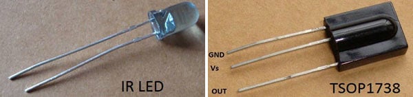
IR LED emits infrared light, and used in TV remotes. This Infrared is received by the receiver TSOP17XX (TSOP 1738used in TV). TSOP17XX receives the modulated Infrared waves and changes its output. TSOP is available in many frequency ranges like TSOP1730, TSOP1738, TSOP1740 etc. Last two digits represent the frequency (in Khz) of modulated IR rays, on which TSOP responds. Like for example TSOP1738 reacts when it receives the IR radiation modulated at 38Khz. TSOP output is active low, means it becomes LOW when IR is detected.
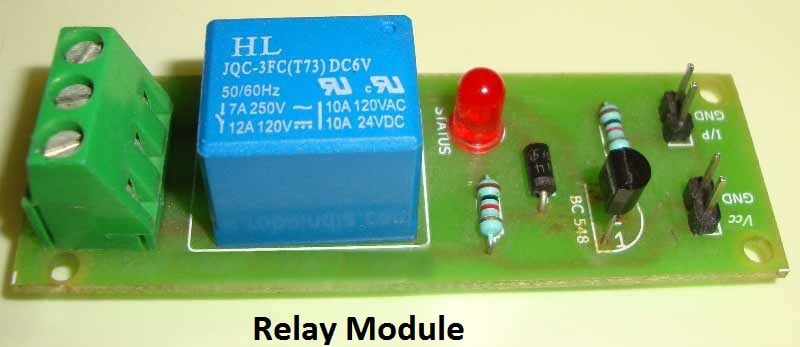
In this remote controlled switch circuit we are using TV remote to ON/OFF the AC light by pressing any button of remote, and using the TSOP1738 at receiver end. Receiver circuit is connected to AC appliance via Relay, so that we can control the light remotely. We have used IC 4017 to convert it into a push ON, push OFF switch. Go through this article to understand the IR Transmitter and Receiver.
Normally when we press any button of TV/DVD player remote, Light glows and as soon as we release Button, it becomes OFF. Now it can be converted into a PUSH ON and PUSH OFF toggle switch using IC CD4017. IC CD4017 is a CMOS decade counter IC. It can produce output at the 10 pins sequentially, i.e. it produces output one by one at the 10 output pins. Output is switched to one pin to another by applying a clock pulse at pin 14.
When firstly, power is applied to IC 4017, output at PIN 3 (Q0) is HIGH, when we press the button of IR remote, then a LOW to HIGH clock pulse is applied to PIN 14 (first clock pulse) and output at Q0 becomes low and PIN 2(Q1) becomes HIGH. PIN 2 triggers the RELAY module, and the AC light becomes ON. Now this position will remain until the next clock pulse. If we press the Button of IR remote again (second clock pulse), output at Q1 becomes LOW and Q2 becomes HIGH. This will deactivate the Relay and switch off the light. And because Q2 is connected to the RESET pin 15 of 4017, it will reset the IC and again output at Q0 becomes HIGH and Q2 becomes LOW (initial state). So it works like a toggle switch.

Output of TSOP1738 oscillates at the rate of 38KHz, which is applied to clock pulse of 4017. So we have connected a 1uF capacitor across the output of the TSOP so that this 38KHz pulse train is counted as one clock pulse to the IC 4017.
We can also use the IR transmitter circuit to ON/OFF the Bulb, this IR transmitter circuit produces modulated IR at 38KHz like a TV remote. Also we can replace Bulb with any AC appliance, which is to be controlled by remote control.
Video:
XXXX . XXX 4 zero null 0 1 2 3 Motion detector
A motion detector is a device that detects moving objects, particularly people. Such a device is often integrated as a component of a system that automatically performs a task or alerts a user of motion in an area. They form a vital component of security, automated lighting control, home control, energy efficiency, and other useful systems.
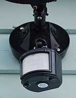 A motion detector attached to an outdoor, automatic light.
Overview

An electronic motion detector contains an optical, microwave, or acoustic sensor, and in many cases a transmitter for illumination. However, a passive sensor senses a signature only from the moving object via emission or reflection, i.e., it can be emitted by the object, or by some ambient emitter such as the sun or a radio station of sufficient strength. Changes in the optical, microwave, or acoustic field in the device's proximity are interpreted by the electronics based on one of the technologies listed below. Most low-cost motion detectors can detect up to distances of at least 15 feet (4.6 m). Specialized systems cost more, but have much longer ranges. Tomographic motion detection systems can cover much larger areas because the radio waves are at frequencies which penetrate most walls and obstructions, and are detected in multiple locations, not only at the location of the transmitter.
Motion detectors have found wide use in domestic and commercial applications. One common application is activating automatic door openers in businesses and public buildings. Motion sensors are also widely used in lieu of a true occupancy sensor in activating street lights or indoor lights in walkways, such as lobbies and staircases. In such smart lighting systems, energy is conserved by only powering the lights for the duration of a timer, after which the person has presumably left the area. A motion detector may be among the sensors of a burglar alarm that is used to alert the home owner or security service when it detects the motion of a possible intruder. Such a detector may also trigger a security camera to record the possible intrusion.
Sensor technology[edit]

Several types of motion detection are in wide use:
- Passive infrared (PIR)
- Passive infrared (PIR) sensors are sensitive to a person's skin temperature through emitted black body radiation at mid-infrared wavelengths, in contrast to background objects at room temperature. No energy is emitted from the sensor, thus the name passive infrared. This distinguishes it from the electric eye for instance (not usually considered a motion detector), in which the crossing of a person or vehicle interrupts a visible or infrared beam.
- Microwave
- These detect motion through the principle of Doppler radar, and are similar to a radar speed gun. A continuous wave of microwave radiation is emitted, and phase shifts in the reflected microwaves due to motion of an object toward (or away from) the receiver result in a heterodyne signal at a low audio frequency.
- Ultrasonic
- An ultrasonic wave (sound at a frequency higher than a human ear can hear) is emitted and reflections from nearby objects are received.[1] Exactly as in Doppler radar, heterodyne detection of the received field indicates motion. The detected doppler shift is also at low audio frequencies (for walking speeds) since the ultrasonic wavelength of around a centimeter is similar to the wavelengths used in microwave motion detectors. One potential drawback of ultrasonic sensors is that the sensor can be sensitive to motion in areas where coverage is undesired, for instance, due to reflections of sound waves around corners.[2] Such extended coverage may be desirable for lighting control, where the goal is detection of any occupancy in an area. But for opening an automatic door, for example, a sensor selective to traffic in the path toward the door is superior.
- Tomographic motion detector
- These systems sense disturbances to radio waves as they pass from node to node of a mesh network. They have the ability to detect over large areas completely because they can sense through walls and other obstructions.
- Video camera software
- With the proliferation of low-cost digital cameras able to shoot video, it is possible to use the output of such a camera to detect motion in its field of view using software. This solution is particularly attractive when the intent is to record video triggered by motion detection, as no hardware beyond the camera and computer is needed. Since the observed field may be normally illuminated, this may be considered another passive technology. However it can also be used together with near-infrared illumination to detect motion in the dark, that is, with the illumination at a wavelength undetectable by a human eye.
- Gesture detector
- Photodetectors and infrared lighting elements can support digital screens to detect hand motions and gestures with the aid of machine learning algorithms.[3]
Dual-technology motion detectors[edit]
Many modern motion detectors use combinations of different technologies. While combining multiple sensing technologies into one detector can help reduce false triggering, it does so at the expense of reduced detection probabilities and increased vulnerability.[citation needed] For example, many dual-tech sensors combine both a PIR sensor and a microwave sensor into one unit. For motion to be detected, both sensors must trip together.[citation needed] This lowers the probability of a false alarm since heat and light changes may trip the PIR but not the microwave, or moving tree branches may trigger the microwave but not the PIR. If an intruder is able to fool either the PIR or microwave, however, the sensor will not detect it.[citation needed]
Often, PIR technology is paired with another model to maximize accuracy and reduce energy use.[citation needed] PIR draws less energy than emissive microwave detection, and so many sensors are calibrated so that when the PIR sensor is tripped, it activates a microwave sensor.[citation needed][citation needed] If the latter also picks up an intruder, then the alarm is sounded.
Sensor technology
Several types of motion detection are in wide use:
- Passive infrared (PIR)
- Passive infrared (PIR) sensors are sensitive to a person's skin temperature through emitted black body radiation at mid-infrared wavelengths, in contrast to background objects at room temperature. No energy is emitted from the sensor, thus the name passive infrared. This distinguishes it from the electric eye for instance (not usually considered a motion detector), in which the crossing of a person or vehicle interrupts a visible or infrared beam.
- Microwave
- These detect motion through the principle of Doppler radar, and are similar to a radar speed gun. A continuous wave of microwave radiation is emitted, and phase shifts in the reflected microwaves due to motion of an object toward (or away from) the receiver result in a heterodyne signal at a low audio frequency.
- Ultrasonic
- An ultrasonic wave (sound at a frequency higher than a human ear can hear) is emitted and reflections from nearby objects are received.[1] Exactly as in Doppler radar, heterodyne detection of the received field indicates motion. The detected doppler shift is also at low audio frequencies (for walking speeds) since the ultrasonic wavelength of around a centimeter is similar to the wavelengths used in microwave motion detectors. One potential drawback of ultrasonic sensors is that the sensor can be sensitive to motion in areas where coverage is undesired, for instance, due to reflections of sound waves around corners.[2] Such extended coverage may be desirable for lighting control, where the goal is detection of any occupancy in an area. But for opening an automatic door, for example, a sensor selective to traffic in the path toward the door is superior.
- Tomographic motion detector
- These systems sense disturbances to radio waves as they pass from node to node of a mesh network. They have the ability to detect over large areas completely because they can sense through walls and other obstructions.
- Video camera software
- With the proliferation of low-cost digital cameras able to shoot video, it is possible to use the output of such a camera to detect motion in its field of view using software. This solution is particularly attractive when the intent is to record video triggered by motion detection, as no hardware beyond the camera and computer is needed. Since the observed field may be normally illuminated, this may be considered another passive technology. However it can also be used together with near-infrared illumination to detect motion in the dark, that is, with the illumination at a wavelength undetectable by a human eye.
- Gesture detector
- Photodetectors and infrared lighting elements can support digital screens to detect hand motions and gestures with the aid of machine learning algorithms.[3]
Dual-technology motion detectors[edit]
Many modern motion detectors use combinations of different technologies. While combining multiple sensing technologies into one detector can help reduce false triggering, it does so at the expense of reduced detection probabilities and increased vulnerability.[citation needed] For example, many dual-tech sensors combine both a PIR sensor and a microwave sensor into one unit. For motion to be detected, both sensors must trip together.[citation needed] This lowers the probability of a false alarm since heat and light changes may trip the PIR but not the microwave, or moving tree branches may trigger the microwave but not the PIR. If an intruder is able to fool either the PIR or microwave, however, the sensor will not detect it.[citation needed]
Often, PIR technology is paired with another model to maximize accuracy and reduce energy use.[citation needed] PIR draws less energy than emissive microwave detection, and so many sensors are calibrated so that when the PIR sensor is tripped, it activates a microwave sensor.[citation needed][citation needed] If the latter also picks up an intruder, then the alarm is sounded.
See also
- Gesture detector
- Photodetectors and infrared lighting elements can support digital screens to detect hand motions and gestures with the aid of machine learning algorithms.
Dual-technology motion detectors
Many modern motion detectors use combinations of different technologies. While combining multiple sensing technologies into one detector can help reduce false triggering, it does so at the expense of reduced detection probabilities and increased vulnerability.[ For example, many dual-tech sensors combine both a PIR sensor and a microwave sensor into one unit. For motion to be detected, both sensors must trip together.[ This lowers the probability of a false alarm since heat and light changes may trip the PIR but not the microwave, or moving tree branches may trigger the microwave but not the PIR. If an intruder is able to fool either the PIR or microwave, however, the sensor will not detect it.
Often, PIR technology is paired with another model to maximize accuracy and reduce energy use. PIR draws less energy than emissive microwave detection, and so many sensors are calibrated so that when the PIR sensor is tripped, it activates a microwave
sensor.[citation needed][citation needed] If the latter also picks up an intruder, then the alarm is sounded.
XXX . XXX 4 zero null 0 1 2 3 4 How to make remote control car

Do you ever wonder how to make a remote control car/toy or how to make a remote control robot? The objective of this project is to design a low cost remote control toy or robot. There are so many projects available to make RC toys. But here we are providing a simple circuit with low cost electronics components. DIY electronic projects like this will increase your passion to electronics.
The project “How to make a remote control car” is for students to make a low cost car by themselves. It is very useful to study the basics of wireless communication for electronics beginners. Mainly wireless car projects use two types of technologies Infra-Red (IR) and Radio Frequency (RF). IR remote control sends infrared rays to the car circuit. In case of IR remote control, line of sight with the receiving circuit is necessary and its range is only up to 10 meters. But in case of RF remote Radio Frequency waves plays the role, so signal can go through walls and are able to provide a range up to 35 meters.
In our project we are designing an RF remote control. For that we are using an ASK transmitter receiver module. Microcontroller is avoided in the circuit to make it cost effective. ASK module is used as the remote transmitter, two IC’sHT12E and HT12D is used for Encoding and Decoding. Circuit diagram and circuit explanation given below will make you confident enough to make a remote control car.
Block Diagram of DIY Electronic Project Remote Control Car:

Block Description:
Transmitter Section:
Controlling Switches: Four button switches are used in the remote control to move the car backward, forward, left and right.
HT12E Encoder IC: It is a 212 series encoder IC used for wireless communication applications. It is mainly used to convert 12 bit parallel data (8 address bits and 4 data bits) to serial out so that it can be transmitted using a transmitter Module.
RF Tx Module: 434 MHz ASK transmitter module for transmission. It is capable of providing a data rate of about 8kbps.
Battery: 3V button cell is used to power the remote.
Receiver Section:
RF Rx Module: A high sensitivity 434 MHz ASK Receiver module for receiving the data from remote control.
HT12D Decoder IC: It is a 1212 series decoder IC used for wireless communication applications. It converts the serial input to parallel out.
Motor Driver: L293D motor driver is used to drive two motors. L293D provides bidirectional drive current up to 600mA at voltages from 4.5V to 36V.
Motors: Here two BO motors are used which are driven by the motor driver L293D and both of them are connected to robotic wheels to move the car.
Battery: Receiver section need more power than the remote control circuit. So 9V/12V battery is required to power the circuit.
Electronic Components & Modules Required:
Only basic electronic components were used here for the project. All datasheets and link to buy the components online are provided below. Refer datasheets and get familiarize about the components used for the circuit before starting the DIY project.
Resistor:
- 1K Resistor: 8
Semiconductors:
Modules:
Miscellaneous:
- 3V Button Cell with holder (Remote): 1
- 9V/12V Battery with holder (Receiver/Car): 1
- Button Switch: 4
- BO Motor: 2
- Robotic Wheels: 4
Circuit Design of Remote Control Car:
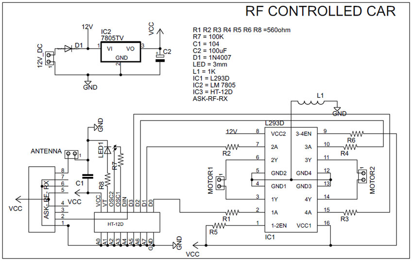

RC car circuit diagram with remote transmitter
Circuit design of this remote control car is simple and is of low cost as we are not using a microcontroller in it. So these type DIY electronic projects are very effective for hobbyists, students and for beginners in electronics field. Main components are two communication ICs (HT12D and HT12E) and an ASK RF transmitter receiver module. They are available in every local shop and online stores in a very low cost.
RC car circuit diagram with remote transmitter is designed in a compact way to make it as small as possible. Remote uses four button switches (S1, S2, S3, and S4) to control the toy. Digital data’s from the switches are encoded by the HT12E encoder IC and are transmitted to the receiver through ASK RF Module. When we press these switches, 4 data bits and 8 address bits are serially encoded and output through the pin “DOUT” is given to the 434 MHz Transmitter. Circuit is so simple due to the simple coupling of ASK module with HT12E and HT12D pair. Remote control is power by a 3V button cell.
Receiver section receives the signal with the help of 434 MHz ASK module and provides it to the decoder IC. “DIN” pin of HT12D gets the data from RF module and checks it three times before decoding. And if received address data matches with the encoder address data, then IC will decode the data bits and provides it directly to L293D motor driver. This driver is used to control the motors forward and backward according to the received signal. An LED is connected to the valid transmit pin of Decoder IC to indicate a valid transmission.
Left Motor Direction
|
Right Motor Direction
|
Direction of Car
|
Forward
|
Forward
|
Forward
|
Forward
|
Backward
|
Right
|
Backward
|
Forward
|
Left
|
Backward
|
Backward
|
Backward
|
PCB
Highly optimized PCB design using Eagle Cad is provided below. Both the PCB design for remote control and car is designed as small as possible. Just print both these PCBs and solder it with the electronic components required. After soldering test all the components with a multimeter.

Remote PCB

Remote Control Car PCB
This DIY project “how to make a RC car” uses only some basic electronics circuitry and mechanical design. So this project is very easy to make and very useful for students. Also this helps in learning about some basic electronics components and about Radio Frequency communication. As our circuit using low cost electronic components it is very helpful for students to learn electronics through practical knowledge.
XXX . XXX 4 zero null 0 1 2 3 4 remote sense Internet of Things: Architectures, Protocols, and Applications
The Internet of Things (IoT) is defined as a paradigm in which objects equipped with sensors, actuators, and processors communicate with each other to serve a meaningful purpose. In this paper, we survey state-of-the-art methods, protocols, and applications in this new emerging area. This survey paper proposes a novel taxonomy for IoT technologies, highlights some of the most important technologies, and profiles some applications that have the potential to make a striking difference in human life, especially for the differently abled and the elderly. As compared to similar survey papers in the area, this paper is far more comprehensive in its coverage and exhaustively covers most major technologies spanning from sensors to applications.
1. Introduction
Today the Internet has become ubiquitous, has touched almost every corner of the globe, and is affecting human life in unimaginable ways. However, the journey is far from over. We are now entering an era of even more pervasive connectivity where a very wide variety of appliances will be connected to the web. We are entering an era of the “Internet of Things” (abbreviated as IoT). This term has been defined by different authors in many different ways. Let us look at two of the most popular definitions. Vermesan et al. [1] define the Internet of Things as simply an interaction between the physical and digital worlds. The digital world interacts with the physical world using a plethora of sensors and actuators. Another definition by Peña-López et al. [2] defines the Internet of Things as a paradigm in which computing and networking capabilities are embedded in any kind of conceivable object. We use these capabilities to query the state of the object and to change its state if possible. In common parlance, the Internet of Things refers to a new kind of world where almost all the devices and appliances that we use are connected to a network. We can use them collaboratively to achieve complex tasks that require a high degree of intelligence.
For this intelligence and interconnection, IoT devices are equipped with embedded sensors, actuators, processors, and transceivers. IoT is not a single technology; rather it is an agglomeration of various technologies that work together in tandem.
Sensors and actuators are devices, which help in interacting with the physical environment. The data collected by the sensors has to be stored and processed intelligently in order to derive useful inferences from it. Note that we broadly define the term sensor; a mobile phone or even a microwave oven can count as a sensor as long as it provides inputs about its current state (internal state + environment). An actuator is a device that is used to effect a change in the environment such as the temperature controller of an air conditioner.
The storage and processing of data can be done on the edge of the network itself or in a remote server. If any preprocessing of data is possible, then it is typically done at either the sensor or some other proximate device. The processed data is then typically sent to a remote server. The storage and processing capabilities of an IoT object are also restricted by the resources available, which are often very constrained due to limitations of size, energy, power, and computational capability. As a result the main research challenge is to ensure that we get the right kind of data at the desired level of accuracy. Along with the challenges of data collection, and handling, there are challenges in communication as well. The communication between IoT devices is mainly wireless because they are generally installed at geographically dispersed locations. The wireless channels often have high rates of distortion and are unreliable. In this scenario reliably communicating data without too many retransmissions is an important problem and thus communication technologies are integral to the study of IoT devices.
Now, after processing the received data, some action needs to be taken on the basis of the derived inferences. The nature of actions can be diverse. We can directly modify the physical world through actuators. Or we may do something virtually. For example, we can send some information to other smart things.
The process of effecting a change in the physical world is often dependent on its state at that point of time. This is called context awareness. Each action is taken keeping in consideration the context because an application can behave differently in different contexts. For example, a person may not like messages from his office to interrupt him when he is on vacation.
Sensors, actuators, compute servers, and the communication network form the core infrastructure of an IoT framework. However, there are many software aspects that need to be considered. First, we need a middleware that can be used to connect and manage all of these heterogeneous components. We need a lot of standardization to connect many different devices. We shall discuss methods to exchange information and prevailing standards in Section 7.
The Internet of Things finds various applications in health care, fitness, education, entertainment, social life, energy conservation, environment monitoring, home automation, and transport systems. We shall focus on these application areas in Section 9. We shall find that, in all these application areas, IoT technologies have significantly been able to reduce human effort and improve the quality of life.
2. Architecture of IoT
There is no single consensus on architecture for IoT, which is agreed universally. Different architectures have been proposed by different researchers.
2.1. Three- and Five-Layer Architectures
The most basic architecture is a three-layer architecture [3–5] as shown in Figure 1. It was introduced in the early stages of research in this area. It has three layers, namely, the perception, network, and application layers.(i)The perception layer is the physical layer, which has sensors for sensing and gathering information about the environment. It senses some physical parameters or identifies other smart objects in the environment.(ii)The network layer is responsible for connecting to other smart things, network devices, and servers. Its features are also used for transmitting and processing sensor data.(iii)The application layer is responsible for delivering application specific services to the user. It defines various applications in which the Internet of Things can be deployed, for example, smart homes, smart cities, and smart health.
The three-layer architecture defines the main idea of the Internet of Things, but it is not sufficient for research on IoT because research often focuses on finer aspects of the Internet of Things. That is why, we have many more layered architectures proposed in the literature. One is the five-layer architecture, which additionally includes the processing and business layers [3–6]. The five layers are perception, transport, processing, application, and business layers (see Figure 1). The role of the perception and application layers is the same as the architecture with three layers. We outline the function of the remaining three layers.(i)The transport layer transfers the sensor data from the perception layer to the processing layer and vice versa through networks such as wireless, 3G, LAN, Bluetooth, RFID, and NFC.(ii)The processing layer is also known as the middleware layer. It stores, analyzes, and processes huge amounts of data that comes from the transport layer. It can manage and provide a diverse set of services to the lower layers. It employs many technologies such as databases, cloud computing, and big data processing modules.(iii)The business layer manages the whole IoT system, including applications, business and profit models, and users’ privacy. The business layer is out of the scope of this paper. Hence, we do not discuss it further.
Another architecture proposed by Ning and Wang [7] is inspired by the layers of processing in the human brain. It is inspired by the intelligence and ability of human beings to think, feel, remember, make decisions, and react to the physical environment. It is constituted of three parts. First is the human brain, which is analogous to the processing and data management unit or the data center. Second is the spinal cord, which is analogous to the distributed network of data processing nodes and smart gateways. Third is the network of nerves, which corresponds to the networking components and sensors.
2.2. Cloud and Fog Based Architectures
Let us now discuss two kinds of systems architectures: cloud and fog computing (see the reference architectures in [8]). Note that this classification is different from the classification in Section 2.1, which was done on the basis of protocols.
In particular, we have been slightly vague about the nature of data generated by IoT devices, and the nature of data processing. In some system architectures the data processing is done in a large centralized fashion by cloud computers. Such a cloud centric architecture keeps the cloud at the center, applications above it, and the network of smart things below it [9]. Cloud computing is given primacy because it provides great flexibility and scalability. It offers services such as the core infrastructure, platform, software, and storage. Developers can provide their storage tools, software tools, data mining, and machine learning tools, and visualization tools through the cloud.
Lately, there is a move towards another system architecture, namely, fog computing [10–12], where the sensors and network gateways do a part of the data processing and analytics. A fog architecture [13] presents a layered approach as shown in Figure 2, which inserts monitoring, preprocessing, storage, and security layers between the physical and transport layers. The monitoring layer monitors power, resources, responses, and services. The preprocessing layer performs filtering, processing, and analytics of sensor data. The temporary storage layer provides storage functionalities such as data replication, distribution, and storage. Finally, the security layer performs encryption/decryption and ensures data integrity and privacy. Monitoring and preprocessing are done on the edge of the network before sending data to the cloud.
Often the terms “fog computing” and “edge computing” are used interchangeably. The latter term predates the former and is construed to be more generic. Fog computing originally termed by Cisco refers to smart gateways and smart sensors, whereas edge computing is slightly more penetrative in nature. This paradigm envisions adding smart data preprocessing capabilities to physical devices such as motors, pumps, or lights. The aim is to do as much of preprocessing of data as possible in these devices, which are termed to be at the edge of the network. In terms of the system architecture, the architectural diagram is not appreciably different from Figure 2. As a result, we do not describe edge computing separately.
Finally, the distinction between protocol architectures and system architectures is not very crisp. Often the protocols and the system are codesigned. We shall use the generic 5-layer IoT protocol stack (architectural diagram presented in Figure 2) for both the fog and cloud architectures.
2.3. Social IoT
Let us now discuss a new paradigm: social IoT (SIoT). Here, we consider social relationships between objects the same way as humans form social relationships (see [14]). Here are the three main facets of an SIoT system:(i)The SIoT is navigable. We can start with one device and navigate through all the devices that are connected to it. It is easy to discover new devices and services using such a social network of IoT devices.(ii)A need of trustworthiness (strength of the relationship) is present between devices (similar to friends on Facebook).(iii)We can use models similar to studying human social networks to also study the social networks of IoT devices.
2.3.1. Basic Components
In a typical social IoT setting, we treat the devices and services as bots where they can set up relationships between them and modify them over time. This will allow us to seamlessly let the devices cooperate among each other and achieve a complex task.
To make such a model work, we need to have many interoperating components. Let us look at some of the major components in such a system.(1)ID: we need a unique method of object identification. An ID can be assigned to an object based on traditional parameters such as the MAC ID, IPv6 ID, a universal product code, or some other custom method.(2)Metainformation: along with an ID, we need some metainformation about the device that describes its form and operation. This is required to establish appropriate relationships with the device and also appropriately place it in the universe of IoT devices.(3)Security controls: this is similar to “friend list” settings on Facebook. An owner of a device might place restrictions on the kinds of devices that can connect to it. These are typically referred to as owner controls.(4)Service discovery: such kind of a system is like a service cloud, where we need to have dedicated directories that store details of devices providing certain kinds of services. It becomes very important to keep these directories up to date such that devices can learn about other devices.(5)Relationship management: this module manages relationships with other devices. It also stores the types of devices that a given device should try to connect with based on the type of services provided. For example, it makes sense for a light controller to make a relationship with a light sensor.(6)Service composition: this module takes the social IoT model to a new level. The ultimate goal of having such a system is to provide better integrated services to users. For example, if a person has a power sensor with her air conditioner and this device establishes a relationship with an analytics engine, then it is possible for the ensemble to yield a lot of data about the usage patterns of the air conditioner. If the social model is more expansive, and there are many more devices, then it is possible to compare the data with the usage patterns of other users and come up with even more meaningful data. For example, users can be told that they are the largest energy consumers in their community or among their Facebook friends.
2.3.2. Representative Architecture
Most architectures proposed for the SIoT have a server side architecture as well. The server connects to all the interconnected components, aggregates (composes) the services, and acts as a single point of service for users.
The server side architecture typically has three layers. The first is the base layer that contains a database that stores details of all the devices, their attributes, metainformation, and their relationships. The second layer (Component layer) contains code to interact with the devices, query their status, and use a subset of them to effect a service. The topmost layer is the application layer, which provides services to the users.
On the device (object) side, we broadly have two layers. The first is the object layer, which allows a device to connect to other devices, talk to them (via standardized protocols), and exchange information. The object layer passes information to the social layer. The social layer manages the execution of users’ applications, executes queries, and interacts with the application layer on the server.
3. Taxonomy
Let us now propose taxonomy for research in IoT technologies (see Figure 3). Our taxonomy is based on the architectural elements of IoT as presented in Section 2.
The first architectural component of IoT is the perception layer. It collects data using sensors, which are the most important drivers of the Internet of Things [15]. There are various types of sensors used in diverse IoT applications. The most generic sensor available today is the smartphone. The smartphone itself has many types of sensors embedded in it [16] such as the location sensor (GPS), movement sensors (accelerometer, gyroscope), camera, light sensor, microphone, proximity sensor, and magnetometer. These are being heavily used in different IoT applications. Many other types of sensors are beginning to be used such as sensors for measuring temperature, pressure, humidity, medical parameters of the body, chemical and biochemical substances, and neural signals. A class of sensors that stand out is infrared sensors that predate smartphones. They are now being used widely in many IoT applications: IR cameras, motion detectors, measuring the distance to nearby objects, presence of smoke and gases, and as moisture sensors. We shall discuss the different types of sensors used in IoT applications in Section 5.
Subsequently, we shall discuss related work in data preprocessing. Such applications (also known as fog computing applications) mainly filter and summarize data before sending it on the network. Such units typically have a little amount of temporary storage, a small processing unit, and some security features.
The next architectural component that we shall discuss is communication. We shall discuss related work (in Section 7) on different communication technologies used for the Internet of Things. Different entities communicate over the network [17–19] using a diverse set of protocols and standards. The most common communication technologies for short range low power communication protocols are RFID (Radio Frequency Identification) and NFC (Near Field Communication). For the medium range, they are Bluetooth, Zigbee, and WiFi. Communication in the IoT world requires special networking protocols and mechanisms. Therefore, new mechanisms and protocols have been proposed and implemented for each layer of the networking stack, according to the requirements imposed by IoT devices.
We shall subsequently look at two kinds of software components: middleware and applications. The middleware creates an abstraction for the programmer such that the details of the hardware can be hidden. This enhances interoperability of smart things and makes it easy to offer different kinds of services [20]. There are many commercial and open source offerings for providing middleware services to IoT devices. Some examples are OpenIoT [21], MiddleWhere [22], Hydra [23], FiWare [24], and Oracle Fusion Middleware. Finally, we discuss the applications of IoT in Section 9. We primarily focus on home automation, ambient assisted living, health and fitness, smart vehicular systems, smart cities, smart environments, smart grids, social life, and entertainment.
4. Related Survey Papers
Our taxonomy describes the technologies in the IoT domain and is classified on the basis of architectural layers. We have tried to cover all subareas and recent technologies in our taxonomy. There have been many survey papers on the Internet of Things in the past. Table 1 shows how our survey is different from other highly cited surveys in the literature.
Let us first consider our novel contributions. Our paper looks at each and every layer in the IoT stack, and as a result the presentation is also far more balanced. A novel addition in our survey is that we have discussed different IoT architectures. This has not been discussed in prior surveys on the Internet of Things. The architecture section also considers newer paradigms such as fog computing, which have also hitherto not been considered. Moreover, our survey nicely categorizes technologies based on the architectural layer that they belong to. We have also thoroughly categorized the network layer and tried to consolidate almost all the technologies that are used in IoT systems. Such kind of a thorough categorization and presentation of technologies is novel to the best of our knowledge.
Along with these novel contributions our survey is far more comprehensive, detailed, and exhaustive as compared to other surveys in the area. Most of the other surveys look at only one or two types of sensors, whereas we describe 9 types of sensors with many examples. Other surveys are also fairly restricted when they discuss communication technologies and applications. We have discussed many types of middleware technologies as well. Prior works have not given middleware technologies this level of attention. We cover 10 communication technologies in detail and consider a large variety of applications encompassing smart homes, health care, logistics, transport, agriculture, environment, smart cities, and green energy. No other survey in this area profiles so many technologies, applications, and use cases.
5. Sensors and Actuators
All IoT applications need to have one or more sensors to collect data from the environment. Sensors are essential components of smart objects. One of the most important aspects of the Internet of Things is context awareness, which is not possible without sensor technology. IoT sensors are mostly small in size, have low cost, and consume less power. They are constrained by factors such as battery capacity and ease of deployment. Schmidt and Van Laerhoven [25] provide an overview of various types of sensors used for building smart applications.
5.1. Mobile Phone Based Sensors
First of all, let us look at the mobile phone, which is ubiquitous and has many types of sensors embedded in it. In specific, the smartphone is a very handy and user friendly device that has a host of built in communication and data processing features. With the increasing popularity of smartphones among people, researchers are showing interest in building smart IoT solutions using smartphones because of the embedded sensors [16, 26]. Some additional sensors can also be used depending upon the requirements. Applications can be built on the smartphone that uses sensor data to produce meaningful results. Some of the sensors inside a modern smartphone are as follows.(1)The accelerometer senses the motion and acceleration of a mobile phone. It typically measures changes in velocity of the smartphone in three dimensions. There are many types of accelerometers [27]. In a mechanical accelerometer, we have a seismic mass in a housing, which is tied to the housing with a spring. The mass takes time to move and is left behind as the housing moves, so the force in the spring can be correlated with the acceleration. In a capacitive accelerometer, capacitive plates are used with the same setup. With a change in velocity, the mass pushes the capacitive plates together, thus changing the capacitance. The rate of change of capacitance is then converted into acceleration. In a piezoelectric accelerometer, piezoelectric crystals are used, which when squeezed generate an electric voltage. The changes in voltage can be translated into acceleration. The data patterns captured by the accelerometer can be used to detect physical activities of the user such as running, walking, and bicycling.(2)The gyroscope detects the orientation of the phone very precisely. Orientation is measured using capacitive changes when a seismic mass moves in a particular direction.(3)The camera and microphone are very powerful sensors since they capture visual and audio information, which can then be analyzed and processed to detect various types of contextual information. For example, we can infer a user’s current environment and the interactions that she is having. To make sense of the audio data, technologies such as voice recognition and acoustic features can be exploited.(4)The magnetometer detects magnetic fields. This can be used as a digital compass and in applications to detect the presence of metals.(5)The GPS (Global Positioning System) detects the location of the phone, which is one of the most important pieces of contextual information for smart applications. The location is detected using the principle of trilateration [28]. The distance is measured from three or more satellites (or mobile phone towers in the case of A-GPS) and coordinates are computed.(6)The light sensor detects the intensity of ambient light. It can be used for setting the brightness of the screen and other applications in which some action is to be taken depending on the intensity of ambient light. For example, we can control the lights in a room.(7)The proximity sensor uses an infrared (IR) LED, which emits IR rays. These rays bounce back when they strike some object. Based on the difference in time, we can calculate the distance. In this way, the distance to different objects from the phone can be measured. For example, we can use it to determine when the phone is close to the face while talking. It can also be used in applications in which we have to trigger some event when an object approaches the phone.(8)Some smartphones such as Samsung’s Galaxy S4 also have a thermometer, barometer, and humidity sensor to measure the temperature, atmospheric pressure, and humidity, respectively.
We have studied many smart applications that use sensor data collected from smartphones. For example, activity detection [29] is achieved by applying machine learning algorithms to the data collected by smartphone sensors. It detects activities such as running, going up and down stairs, walking, driving, and cycling. The application is trained with patterns of data using data sets recorded by sensors when these activities are being performed.
Many health and fitness applications are being built to keep track of a person’s health continuously using smartphones. They keep track of users’ physical activities, diet, exercises, and lifestyle to determine the fitness level and give suggestions to the user accordingly. Wang et al. [30] describe a mobile application that is based completely on a smartphone. They use it to assess the overall mental health and performance of a college student. To track the location and activities in which the student is involved, activity recognition (accelerometer) and GPS data are used. To keep a check on how much the student sleeps, the accelerometer and light sensors are used. For social life and conversations, audio data from a microphone is used. The application also conducts quick questionnaires with the students to know about their mood. All this data can be used to assess the stress levels, social life, behavior, and exercise patterns of a student.
Another application by McClernon and Choudhury [31] detects when the user is going to smoke using context information such as the presence of other smokers, location, and associated activities. The sensors provide information related to the user’s movement, location, visual images, and surrounding sounds. To summarize smartphone sensors are being used to study different kinds of human behavior (see [32]) and to improve the quality of human life.
5.2. Medical Sensors
The Internet of Things can be really beneficial for health care applications. We can use sensors, which can measure and monitor various medical parameters in the human body [33]. These applications can aim at monitoring a patient’s health when they are not in hospital or when they are alone. Subsequently, they can provide real time feedback to the doctor, relatives, or the patient. McGrath and Scanaill [34] have described in detail the different sensors that can be worn on the body for monitoring a person’s health.
There are many wearable sensing devices available in the market. They are equipped with medical sensors that are capable of measuring different parameters such as the heart rate, pulse, blood pressure, body temperature, respiration rate, and blood glucose levels [35]. These wearables include smart watches, wristbands, monitoring patches, and smart textiles.
Moreover, smart watches and fitness trackers are becoming fairly popular in the market as companies such as Apple, Samsung, and Sony are coming up with very innovative features. For example, a smart watch includes features such as connectivity with a smartphone, sensors such as an accelerometer, and a heart rate monitor (see Figure 4).
Figure 4: Smart watches and fitness trackers (source: https://www.pebble.com/ and http://www.fitbit.com/).
Another novel IoT device, which has a lot of promise are monitoring patches that are pasted on the skin. Monitoring patches are like tattoos. They are stretchable and disposable and are very cheap. These patches are supposed to be worn by the patient for a few days to monitor a vital health parameter continuously [15]. All the electronic components are embedded in these rubbery structures. They can even transmit the sensed data wirelessly. Just like a tattoo, these patches can be applied on the skin as shown in Figure 5. One of the most common applications of such patches is to monitor blood pressure.
A very important consideration here is the context [34]. The data collected by the medical sensors must be combined with contextual information such as physical activity. For example, the heart rate depends on the context. It increases when we exercise. In that case, we cannot infer abnormal heart rate. Therefore, we need to combine data from different sensors for making the correct inference.
5.3. Neural Sensors
Today, it is possible to understand neural signals in the brain, infer the state of the brain, and train it for better attention and focus. This is known as neurofeedback [36] (see Figure 6). The technology used for reading brain signals is called EEG (Electroencephalography) or a brain computer interface. The neurons inside the brain communicate electronically and create an electric field, which can be measured from outside in terms of frequencies. Brain waves can be categorized into alpha, beta, gamma, theta, and delta waves depending upon the frequency.
Figure 6: Brain sensing headband with embedded neurosensors (source: http://www.choosemuse.com/).
Based on the type of wave, it can be inferred whether the brain is calm or wandering in thoughts. This type of neurofeedback can be obtained in real time and can be used to train the brain to focus, pay better attention towards things, manage stress, and have better mental well-being.
5.4. Environmental and Chemical Sensors
Environmental sensors are used to sense parameters in the physical environment such as temperature, humidity, pressure, water pollution, and air pollution. Parameters such as the temperature and pressure can be measured with a thermometer and barometer. Air quality can be measured with sensors, which sense the presence of gases and other particulate matter in the air (refer to Sekhar et al. [37] for more details).
Chemical sensors are used to detect chemical and biochemical substances. These sensors consist of a recognition element and a transducer. The electronic nose (e-nose) and electronic tongue (e-tongue) are technologies that can be used to sense chemicals on the basis of odor and taste, respectively [38]. The e-nose and e-tongue consist of an array of chemical sensors coupled with advance pattern recognition software. The sensors inside the e-nose and e-tongue produce complex data, which is then analyzed through pattern recognition to identify the stimulus.
These sensors can be used in monitoring the pollution level in smart cities [39], keeping a check on food quality in smart kitchens, testing food, and agricultural products in supply chain applications.
5.5. Radio Frequency Identification (RFID)
RFID is an identification technology in which an RFID tag (a small chip with an antenna) carries data, which is read by a RFID reader. The tag transmits the data stored in it via radio waves. It is similar to bar code technology. But unlike a traditional bar code, it does not require line of sight communication between the tag and the reader and can identify itself from a distance even without a human operator. The range of RFID varies with the frequency. It can go up to hundreds of meters.
RFID tags are of two types: active and passive. Active tags have a power source and passive tags do not have any power source. Passive tags draw power from the electromagnetic waves emitted by the reader and are thus cheap and have a long lifetime [40, 41].
There are two types of RFID technologies: near and far [40]. A near RFID reader uses a coil through which we pass alternating current and generate a magnetic field. The tag has a smaller coil, which generates a potential due to the ambient changes in the magnetic field. This voltage is then coupled with a capacitor to accumulate a charge, which then powers up the tag chip. The tag can then produce a small magnetic field that encodes the signal to be transmitted, and this can be picked up by the reader.
In far RFID, there is a dipole antenna in the reader, which propagates EM waves. The tag also has a dipole antenna on which an alternating potential difference appears and it is powered up. It can then use this power to transmit messages.
RFID technology is being used in various applications such as supply chain management, access control, identity authentication, and object tracking. The RFID tag is attached to the object to be tracked and the reader detects and records its presence when the object passes by it. In this manner, object movement can be tracked and RFID can serve as a search engine for smart things.
For access control, an RFID tag is attached to the authorized object. For example, small chips are glued to the front of vehicles. When the car reaches a barricade on which there is a reader, it reads the tag data and decides whether it is an authorized car. If yes, it opens automatically. RFID cards are issued to the people, who can then be identified by a RFID reader and given access accordingly.
The low level data collected from the RFID tags can be transformed into higher level insights in IoT applications [42]. There are many user level tools available, in which all the data collected by particular RFID readers and data associated with the RFID tags can be managed. The high level data can be used to draw inferences and take further action.
5.6. Actuators
Let us look at some examples of actuators that are used in the Internet of Things. An actuator is a device, which can effect a change in the environment by converting electrical energy into some form of useful energy. Some examples are heating or cooling elements, speakers, lights, displays, and motors.
The actuators, which induce motion, can be classified into three categories, namely, electrical, hydraulic, and pneumatic actuators depending on their operation. Hydraulic actuators facilitate mechanical motion using fluid or hydraulic power. Pneumatic actuators use the pressure of compressed air and electrical ones use electrical energy.
As an example, we can consider a smart home system, which consists of many sensors and actuators. The actuators are used to lock/unlock the doors, switch on/off the lights or other electrical appliances, alert users of any threats through alarms or notifications, and control the temperature of a home (via a thermostat).
A sophisticated example of an actuator used in IoT is a digital finger, which is used to turn on/off the switches (or anything which requires small motion) and is controlled wirelessly.
6. Preprocessing
As smart things collect huge amount of sensor data, compute and storage resources are required to analyze, store, and process this data. The most common compute and storage resources are cloud based because the cloud offers massive data handling, scalability, and flexibility. But this will not be sufficient to meet the requirements of many IoT applications because of the following reasons [43].(1)Mobility: most of the smart devices are mobile. Their changing location makes it difficult to communicate with the cloud data center because of changing network conditions across different locations.(2)Reliable and real time actuation: communicating with the cloud and getting back responses takes time. Latency sensitive applications, which need real time responses, may not be feasible with this model. Also, the communication may be lossy due to wireless links, which can lead to unreliable data.(3)Scalability: more devices means more requests to the cloud, thereby increasing the latency.(4)Power constraints: communication consumes a lot of power, and IoT devices are battery powered. They thus cannot afford to communicate all the time.
To solve the problem of mobility, researchers have proposed mobile cloud computing (MCC) [44]. But there are still problems associated with latency and power. MCC also suffers from mobility problems such as frequently changing network conditions due to which problems such as signal fading and service degradation arise.
As a solution to these problems, we can bring some compute and storage resources to the edge of the network instead of relying on the cloud for everything. This concept is known as fog computing [11, 45] (also see Section 2.2). The fog can be viewed as a cloud, which is close to the ground. Data can be stored, processed, filtered, and analyzed on the edge of the network before sending it to the cloud through expensive communication media. The fog and cloud paradigms go together. Both of them are required for the optimal performance of IoT applications. A smart gateway [13] can be employed between underlying networks and the cloud to realize fog computing as shown in Figure 7.
The features of fog computing [11] are as follows:(1)Low latency: less time is required to access computing and storage resources on fog nodes (smart gateways).(2)Location awareness: as the fog is located on the edge of the network, it is aware of the location of the applications and their context. This is beneficial as context awareness is an important feature of IoT applications.(3)Distributed nodes: fog nodes are distributed unlike centralized cloud nodes. Multiple fog nodes need to be deployed in distributed geographical areas in order to provide services to mobile devices in those areas. For example, in vehicular networks, deploying fog nodes at highways can provide low latency data/video streaming to vehicles.(4)Mobility: the fog supports mobility as smart devices can directly communicate with smart gateways present in their proximity.(5)Real time response: fog nodes can give an immediate response unlike the cloud, which has a much greater latency.(6)Interaction with the cloud: fog nodes can further interact with the cloud and communicate only that data, which is required to be sent to the cloud.
The tasks performed by a smart gateway [46] are collecting sensor data, preprocessing and filtering collected data, providing compute, storage and networking services to IoT devices, communicating with the cloud and sending only necessary data, monitoring power consumption of IoT devices, monitoring activities and services of IoT devices, and ensuring security and privacy of data. Some applications of fog computing are as follows [10, 11]:(1)Smart vehicular networks: smart traffic lights are deployed as smart gateways to locally detect pedestrians and vehicles through sensors, calculate their distance and speed, and finally infer traffic conditions. This is used to warn oncoming vehicles. These sensors also interact with neighboring smart traffic lights to perform traffic management tasks. For example, if sensors detect an approaching ambulance, they can change the traffic lights to let the ambulance pass first and also inform other lights to do so. The data collected by these smart traffic lights are locally analyzed in real time to serve real time needs of traffic management. Further, data from multiple gateways is combined and sent to the cloud for further global analysis of traffic in the city.(2)Smart grid: the smart electrical grid facilitates load balancing of energy on the basis of usage and availability. This is done in order to switch automatically to alternative sources of energy such as solar and wind power. This balancing can be done at the edge of the network using smart meters or microgrids connected by smart gateways. These gateways can analyze and process data. They can then project future energy demand, calculate the availability and price of power, and supply power from both conventional and alternative sources to consumers.
7. Communication
As the Internet of Things is growing very rapidly, there are a large number of heterogeneous smart devices connecting to the Internet. IoT devices are battery powered, with minimal compute and storage resources. Because of their constrained nature, there are various communication challenges involved, which are as follows [19]:(1)Addressing and identification: since millions of smart things will be connected to the Internet, they will have to be identified through a unique address, on the basis of which they communicate with each other. For this, we need a large addressing space, and a unique address for each smart object.(2)Low power communication: communication of data between devices is a power consuming task, specially, wireless communication. Therefore, we need a solution that facilitates communication with low power consumption.(3)Routing protocols with low memory requirement and efficient communication patterns.(4)High speed and nonlossy communication.(5)Mobility of smart things.
IoT devices typically connect to the Internet through the IP (Internet Protocol) stack. This stack is very complex and demands a large amount of power and memory from the connecting devices. The IoT devices can also connect locally through non-IP networks, which consume less power, and connect to the Internet via a smart gateway. Non-IP communication channels such as Bluetooth, RFID, and NFC are fairly popular but are limited in their range (up to a few meters). Therefore, their applications are limited to small personal area networks. Personal area networks (PAN) are being widely used in IoT applications such as wearables connected to smartphones. For increasing the range of such local networks, there was a need to modify the IP stack so as to facilitate low power communication using the IP stack. One of the solutions is 6LoWPAN, which incorporates IPv6 with low power personal area networks. The range of a PAN with 6LoWPAN is similar to local area networks, and the power consumption is much lower.
The leading communication technologies used in the IoT world are IEEE 802.15.4, low power WiFi, 6LoWPAN, RFID, NFC, Sigfox, LoraWAN, and other proprietary protocols for wireless networks.
7.1. Near Field Communication (NFC)
Near Field Communication [47–49] is a very short range wireless communication technology, through which mobile devices can interact with each other over a distance of few centimeters only. All types of data can be transferred between two NFC enabled devices in seconds by bringing them close to each other. This technology is based on RFID. It uses variations in the magnetic field to communicate data between two NFC enabled devices. NFC operates over a frequency band of 13.56 MHz, which is the same as high frequency RFID. There are two modes of operation: active and passive. In the active mode, both the devices generate magnetic fields, while in the passive mode, only one device generates the field and the other uses load modulation to transfer the data. The passive mode is useful in battery powered devices to optimize energy use. One benefit of the requirement of close proximity between devices is that it is useful for secure transactions such as payments. Finally, note that NFC can be used for two-way communication unlike RFID. Consequently, almost all smartphones in the market today are NFC enabled.
7.2. Wireless Sensor Networks (WSN) Based on IP for Smart Objects
Many times, data from a single sensor is not useful in monitoring large areas and complex activities. Different sensor nodes need to interact with each other wirelessly. The disadvantage of non-IP technologies such as RFID, NFC, and Bluetooth is that their range is very small. So, they cannot be used in many applications, where a large area needs to be monitored through many sensor nodes deployed in diverse locations. A wireless sensor network (WSN) consists of tens to thousands of sensor nodes connected using wireless technologies. They collect data about the environment and communicate it to gateway devices that relay the information to the cloud over the Internet. The communication between nodes in a WSN may be direct or multihop. The sensor nodes are of a constrained nature, but gateway nodes have sufficient power and processing resources. The popular network topologies used in a WSN are a star, a mesh, and a hybrid network. Most of the communication in WSN is based on the IEEE 802.15.4 standard (discussed in Section 7.3). There are clearly a lot of protocols that can be used in IoT scenarios. Let us discuss the design of a typical IoT network protocol stack with the most popular alternatives.
7.3. IoT Network Protocol Stack
The Internet Engineering Task Force (IETF) has developed alternative protocols for communication between IoT devices using IP because IP is a flexible and reliable standard [50, 51]. The Internet Protocol for Smart Objects (IPSO) Alliance has published various white papers describing alternative protocols and standards for the layers of the IP stack and an additional adaptation layer, which is used for communication [51–54] between smart objects.
(1) Physical and MAC Layer (IEEE 802.15.4). The IEEE 802.15.4 protocol is designed for enabling communication between compact and inexpensive low power embedded devices that need a long battery life. It defines standards and protocols for the physical and link (MAC) layer of the IP stack. It supports low power communication along with low cost and short range communication. In the case of such resource constrained environments, we need a small frame size, low bandwidth, and low transmit power.
Transmission requires very little power (maximum one milliwatt), which is only one percent of that used in WiFi or cellular networks. This limits the range of communication. Because of the limited range, the devices have to operate cooperatively in order to enable multihop routing over longer distances. As a result, the packet size is limited to 127 bytes only, and the rate of communication is limited to 250 kbps. The coding scheme in IEEE 802.15.4 has built in redundancy, which makes the communication robust, allows us to detect losses, and enables the retransmission of lost packets. The protocol also supports short 16-bit link addresses to decrease the size of the header, communication overheads, and memory requirements [55].
Readers can refer to the survey by Vasseur et al. [54] for more information on different physical and link layer technologies for communication between smart objects.
(2) Adaptation Layer. IPv6 is considered the best protocol for communication in the IoT domain because of its scalability and stability. Such bulky IP protocols were initially not thought to be suitable for communication in scenarios with low power wireless links such as IEEE 802.15.4.
6LoWPAN, an acronym for IPv6 over low power wireless personal area networks, is a very popular standard for wireless communication. It enables communication using IPv6 over the IEEE 802.15.4 [52] protocol. This standard defines an adaptation layer between the 802.15.4 link layer and the transport layer. 6LoWPAN devices can communicate with all other IP based devices on the Internet. The choice of IPv6 is because of the large addressing space available in IPv6. 6LoWPAN networks connect to the Internet via a gateway (WiFi or Ethernet), which also has protocol support for conversion between IPv4 and IPv6 as today’s deployed Internet is mostly IPv4. IPv6 headers are not small enough to fit within the small 127 byte MTU of the 802.15.4 standard. Hence, squeezing and fragmenting the packets to carry only the essential information is an optimization that the adaptation layer performs.
Specifically, the adaptation layer performs the following three optimizations in order to reduce communication overhead [55]:(i)Header compression 6loWPAN defines header compression of IPv6 packets for decreasing the overhead of IPv6. Some of the fields are deleted because they can be derived from link level information or can be shared across packets.(ii)Fragmentation: the minimum MTU size (maximum transmission unit) of IPv6 is 1280 bytes. On the other hand, the maximum size of a frame in IEEE 802.15.4 is 127 bytes. Therefore, we need to fragment the IPv6 packet. This is done by the adaptation layer.(iii)Link layer forwarding 6LoWPAN also supports mesh under routing, which is done at the link layer using link level short addresses instead of in the network layer. This feature can be used to communicate within a 6LoWPAN network.
(3) Network Layer. The network layer is responsible for routing the packets received from the transport layer. The IETF Routing over Low Power and Lossy Networks (ROLL) working group has developed a routing protocol (RPL) for Low Power and Lossy Networks (LLNs) [53].
For such networks, RPL is an open routing protocol, based on distance vectors. It describes how a destination oriented directed acyclic graph (DODAG) is built with the nodes after they exchange distance vectors. A set of constraints and an objective function is used to build the graph with the best path [53]. The objective function and constraints may differ with respect to their requirements. For example, constraints can be to avoid battery powered nodes or to prefer encrypted links. The objective function can aim to minimize the latency or the expected number of packets that need to be sent.
The making of this graph starts from the root node. The root starts sending messages to neighboring nodes, which then process the message and decide whether to join or not depending upon the constraints and the objective function. Subsequently, they forward the message to their neighbors. In this manner, the message travels till the leaf nodes and a graph is formed. Now all the nodes in the graph can send packets upwards hop by hop to the root. We can realize a point to point routing algorithm as follows. We send packets to a common ancestor, from which it travels downwards (towards leaves) to reach the destination.
To manage the memory requirements of nodes, nodes are classified into storing and nonstoring nodes depending upon their ability to store routing information. When nodes are in a nonstoring mode and a downward path is being constructed, the route information is attached to the incoming message and forwarded further till the root. The root receives the whole path in the message and sends a data packet along with the path message to the destination hop by hop. But there is a trade-off here because nonstoring nodes need more power and bandwidth to send additional route information as they do not have the memory to store routing tables.
(4) Transport Layer. TCP is not a good option for communication in low power environments as it has a large overhead owing to the fact that it is a connection oriented protocol. Therefore, UDP is preferred because it is a connectionless protocol and has low overhead.
(5) Application Layer. The application layer is responsible for data formatting and presentation. The application layer in the Internet is typically based on HTTP. However, HTTP is not suitable in resource constrained environments because it is fairly verbose in nature and thus incurs a large parsing overhead. Many alternate protocols have been developed for IoT environments such as CoAP (Constrained Application Protocol) and MQTT (Message Queue Telemetry Transport).(a)Constrained Application Protocol: CoAP can be thought of as an alternative to HTTP. It is used in most IoT applications [56, 57]. Unlike HTTP, it incorporates optimizations for constrained application environments [50]. It uses the EXI (Efficient XML Interchanges) data format, which is a binary data format and is far more efficient in terms of space as compared to plain text HTML/XML. Other supported features are built in header compression, resource discovery, autoconfiguration, asynchronous message exchange, congestion control, and support for multicast messages. There are four types of messages in CoAP: nonconfirmable, confirmable, reset (nack), and acknowledgement. For reliable transmission over UDP, confirmable messages are used [58]. The response can be piggybacked in the acknowledgement itself. Furthermore, it uses DTLS (Datagram Transport Layer Security) for security purposes.(b)Message Queue Telemetry Transport: MQTT is a publish/subscribe protocol that runs over TCP. It was developed by IBM [59] primarily as a client/server protocol. The clients are publishers/subscribers and the server acts as a broker to which clients connect through TCP. Clients can publish or subscribe to a topic. This communication takes place through the broker whose job is to coordinate subscriptions and also authenticate the client for security. MQTT is a lightweight protocol, which makes it suitable for IoT applications. But because of the fact that it runs over TCP, it cannot be used with all types of IoT applications. Moreover, it uses text for topic names, which increases its overhead.
MQTT-S/MQTT-SN is an extension of MQTT [60], which is designed for low power and low cost devices. It is based on MQTT but has some optimizations for WSNs as follows [61]. The topic names are replaced by topic IDs, which reduce the overheads of transmission. Topics do not need registration as they are preregistered. Messages are also split so that only the necessary information is sent. Further, for power conservation, there is an offline procedure for clients who are in a sleep state. Messages can be buffered and later read by clients when they wake up. Clients connect to the broker through a gateway device, which resides within the sensor network and connects to the broker.
7.4. Bluetooth Low Energy (BLE)
Bluetooth Low Energy, also known as “Bluetooth Smart,” was developed by the Bluetooth Special Interest Group. It has a relatively shorter range and consumes lower energy as compared to competing protocols. The BLE protocol stack is similar to the stack used in classic Bluetooth technology. It has two parts: controller and host. The physical and link layer are implemented in the controller. The controller is typically a SOC (System on Chip) with a radio. The functionalities of upper layers are included in the host [62]. BLE is not compatible with classic Bluetooth. Let us look at the differences between classic Bluetooth and BLE [63, 64].
The main difference is that BLE does not support data streaming. Instead, it supports quick transfer of small packets of data (packet size is small) with a data rate of 1 Mbps.
There are two types of devices in BLE: master and slave. The master acts as a central device that can connect to various slaves. Let us consider an IoT scenario where a phone or PC serve as the master and mobile devices such as a thermostat, fitness tracker, smart watch, or any monitoring device act as slaves. In such cases, slaves must be very power efficient. Therefore, to save energy, slaves are by default in sleep mode and wake up periodically to receive packets from the master.
In classic Bluetooth, the connection is on all the time even if no data transfer is going on. Additionally, it supports 79 data channels (1 MHz channel bandwidth) and a data rate of 1 million symbols/s, whereas, BLE supports 40 channels with 2 MHz channel bandwidth (double of classic Bluetooth) and 1 million symbols/s data rate. BLE supports low duty cycle requirements as its packet size is small and the time taken to transmit the smallest packet is as small as 80 s. The BLE protocol stack supports IP based communication also. An experiment conducted by Siekkinen et al. [65] recorded the number of bytes transferred per Joule to show that BLE consumes far less energy as compared to competing protocols such as Zigbee. The energy efficiency of BLE is 2.5 times better than Zigbee.
7.5. Low Power WiFi
The WiFi alliance has recently developed “WiFi HaLow,” which is based on the IEEE 802.11ah standard. It consumes lower power than a traditional WiFi device and also has a longer range. This is why this protocol is suitable for Internet of Things applications. The range of WiFi HaLow is nearly twice that of traditional WiFi.
Like other WiFi devices, devices supporting WiFi HaLow also support IP connectivity, which is important for IoT applications. Let us look at the specifications of the IEEE 802.11ah standard [66, 67]. This standard was developed to deal with wireless sensor network scenarios, where devices are energy constrained and require relatively long range communication. IEEE 802.11ah operates in the sub-gigahertz band (900 MHz). Because of the relatively lower frequency, the range is longer since higher frequency waves suffer from higher attenuation. We can extend the range (currently 1 km) by lowering the frequency further; however, the data rate will also be lower and thus the tradeoff is not justified. IEEE 802.11ah is also designed to support large star shaped networks, where a lot of stations are connected to a single access point.
7.6. Zigbee
It is based on the IEEE 802.15.4 communication protocol standard and is used for personal area networks or PANs [68]. The IEEE 802.15.4 standard has low power MAC and physical layers and has already been explained in Section 7.3. Zigbee was developed by the Zigbee alliance, which works for reliable, low energy, and cheap communication solutions. The range of Zigbee device communication is very small (10–100 meters). The details of the network and application layers are also specified by the Zigbee standard. Unlike BLE, the network layer here provides for multihop routing.
There are three types of devices in a Zigbee network: FFD (Fully Functional Device), RFD (Reduced Functional Device), and one Zigbee coordinator. A FFD node can additionally act as a router. Zigbee supports star, tree, and mesh topologies. The routing scheme depends on the topology. Other features of Zigbee are discovery and maintenance of routes, support for nodes joining/leaving the network, short 16-bit addresses, and multihop routing.
The framework for communication and distributed application development is provided by the application layer. The application layer consists of Application Objects (APO), Application Sublayer (APS), and a Zigbee Device Object (ZDO). APOs are spread over the network nodes. These are pieces of software, which control some underlying device hardware (examples: switch and transducer). The device and network management services are provided by the ZDO, which are then used by the APOs. Data transfer services are provided by the Application Sublayer to the APOs and ZDO. It is responsible for secure communication between the Application Objects. These features can be used to create a large distributed application.
7.7. Integration of RFID and WSN
RFID and wireless sensor networks (WSN) are both important technologies in the IoT domain. RFID can only be used for object identification, but WSNs serve a far greater purpose. The two are very different but merging them has many advantages. The following components can be added to RFID to enhance its usability:(a)Sensing capabilities(b)Multihop communication(c)Intelligence
RFID is inexpensive and uses very little power. That is why its integration with WSN is very useful. The integration is possible in the following ways [69, 70]:(a)Integration of RFID tags with sensors: RFID tags with sensing capabilities are called sensor tags. These sensor tags sense data from the environment and then the RFID reader can read this sensed data from the tag. In such cases, simple RFID protocols are used, where there is only single hop communication. RFID sensing technologies can be further classified on the basis of the power requirement of sensor tags as explained earlier in the section on RFIDs (active and passive) (see Section 5.5).(b)Integration of RFID tags with WSN nodes: the communication capabilities of sensor tags are limited to a single hop. To extend its capabilities, the sensor tag is equipped with a wireless transceiver, little bit of Flash memory, and computational capabilities such that it can initiate communication with other nodes and wireless devices. The nodes can in this fashion be used to form a wireless mesh network. In such networks, sensor tags can communicate with each other over a large range (via intermediate hops). With additional processing capabilities at a node, we can reduce the net amount of data communicated and thus increase the power efficiency of the WSN.(c)Integration of RFID readers with WSN nodes: this type of integration is also done to increase the range of RFID tag readers. The readers are equipped with wireless transceivers and microcontrollers so that they can communicate with each other and therefore, the tag data can reach a reader, which is not in the range of that tag. It takes advantage of multihop communication of wireless sensor network devices. The data from all the RFID readers in the network ultimately reaches a central gateway or base station that processes the data or sends it to a remote server.
These kinds of integrated solutions have many applications in a diverse set of domains such as security, healthcare, and manufacturing.
7.8. Low Power Wide-Area-Networks (LPWAN)
Let us now discuss a protocol for long range communication in power constrained devices. The LPWAN class of protocols is low bit-rate communication technologies for such IoT scenarios.
Let us now discuss some of the most common technologies in this area. Narrow band IoT: it is a technology made for a large number of devices that are energy constrained. It is thus necessary to reduce the bit rate. This protocol can be deployed with both the cellular phone GSM and LTE spectra. The downlink speeds vary between 40 kbps (LTE M2) and 10 Mbps (LTE category 1). Sigfox: it is one more protocol that uses narrow band communication (10 MHz). It uses free sections of the radio spectrum (ISM band) to transmit its data. Instead of 4G networks, Sigfox focuses on using very long waves. Thus, the range can increase to a 1000 kms. Because of this the energy for transmission is significantly lower (0.1%) than contemporary cell phones. Again the cost is bandwidth. It can only transmit 12 bytes per message, and a device is limited to 140 messages per day. This is reasonable for many kinds of applications: submarine applications, sending control (emergency) codes, geolocation, monitoring remote locations, and medical applications. Weightless: it uses a differential binary phase shift keying based method to transmit narrow band signals. To avoid interference, the protocol hops across frequency bands (instead of using CSMA). It supports cryptographic encryption and mobility. Along with frequency hopping, two additional mechanisms are used to reduce collisions. The downlink service uses time division multiple access (TDMA) and the uplink service uses multiple subchannels that are first allocated to transmitting nodes by contacting a central server. Some applications include smart meters, vehicle tracking, health monitoring, and industrial machine monitoring. Neul: this protocol operates in the sub-1 GHz band. It uses small chunks of the TV whitespace spectrum to create low cost and low power networks with very high scalability. It has a 10 km range and uses the Weightless protocol for communication. LoRaWAN: this protocol is similar to Sigfox. It targets wide area network applications and is designed to be a low power protocol. Its data rates can vary from 0.3 kbps to 50 kbps, and it can be used within an urban or a suburban environment (2–5 kms range in a crowded urban area). It was designed to serve as a standard for long range IoT protocols. It thus has features to support multitenancy, enable multiple applications, and include several different network domains.
7.9. Lightweight Application Layer Protocols
Along with physical and MAC layer protocols, we also need application layer protocols for IoT networks. These lightweight protocols need to be able to carry application messages, while simultaneously reducing power as far as possible.
OMA Lightweight M2M (LWM2M) is one such protocol. It defines the communication protocol between a server and a device. The devices often have limited capabilities and are thus referred to as constrained devices. The main aims of the OMA protocol are as follows:(1)Remote device management.(2)Transferring service data/information between different nodes in the LWM2M network.
All the protocols in this class treat all the network resources as objects. Such resources can be created, deleted, and remotely configured. These devices have their unique limitations and can use different kinds of protocols for internally representing information. The LWM2M protocol abstracts all of this away and provides a convenient interface to send messages between a generic LWM2M server and a distributed set of LWM2M clients.
This protocol is often used along with CoAP (Constrained Application Protocol). It is an application layer protocol that allows constrained nodes such as sensor motes or small embedded devices to communicate across the Internet. CoAP seamlessly integrates with HTTP, yet it provides additional facilities such as support for multicast operations. It is ideally suited for small devices because of its low overhead and parsing complexity and reliance on UDP rather than TCP.
8. Middleware
Ubiquitous computing is the core of the Internet of Things, which means incorporating computing and connectivity in all the things around us. Interoperability of such heterogeneous devices needs well-defined standards. But standardization is difficult because of the varied requirements of different applications and devices. For such heterogeneous applications, the solution is to have a middleware platform, which will abstract the details of the things for applications. That is, it will hide the details of the smart things. It should act as a software bridge between the things and the applications. It needs to provide the required services to the application developers [20] so that they can focus more on the requirements of applications rather than on interacting with the baseline hardware. To summarize, the middleware abstracts the hardware and provides an Application Programming Interface (API) for communication, data management, computation, security, and privacy.
The challenges, which are addressed by any IoT middleware, are as follows: [20, 71, 72].(1)Interoperability and programming abstractions: for facilitating collaboration and information exchange between heterogeneous devices, different types of things can interact with each other easily with the help of middleware services. Interoperability is of three types: network, semantic, and syntactic. Network interoperability deals with heterogeneous interface protocols for communication between devices. It insulates the applications from the intricacies of different protocols. Syntactic interoperability ensures that applications are oblivious of different formats, structures, and encoding of data. Semantic interoperability deals with abstracting the meaning of data within a particular domain. It is loosely inspired by the semantic web.(2)Device discovery and management: this feature enables the devices to be aware of all other devices in the neighborhood and the services provided by them. In the Internet of Things, the infrastructure is mostly dynamic. The devices have to announce their presence and the services they provide. The solution needs to be scalable because the devices in an IoT network can increase. Most solutions in this domain are loosely inspired by semantic web technologies. The middleware provides APIs to list the IoT devices, their services, and capabilities. In addition, typically APIs are provided to discover devices based on their capabilities. Finally, any IoT middleware needs to perform load balancing, manage devices based on their levels of battery power, and report problems in devices to the users.(3)Scalability: a large number of devices are expected to communicate in an IoT setup. Moreover, IoT applications need to scale due to ever increasing requirements. This should be managed by the middleware by making required changes when the infrastructure scales.(4)Big data and analytics: IoT sensors typically collect a huge amount of data. It is necessary to analyze all of this data in great detail. As a result a lot of big data algorithms are used to analyze IoT data. Moreover, it is possible that due to the flimsy nature of the network some of the data collected might be incomplete. It is necessary to take this into account and extrapolate data by using sophisticated machine learning algorithms.(5)Security and privacy: IoT applications are mostly related to someone’s personal life or an industry. Security and privacy issues need to be addressed in all such environments. The middleware should have built in mechanisms to address such issues, along with user authentication, and the implementation of access control.(6)Cloud services: the cloud is an important part of an IoT deployment. Most of the sensor data is analyzed and stored in a centralized cloud. It is necessary for IoT middleware to seamlessly run on different types of clouds and to enable users to leverage the cloud to get better insights from the data collected by the sensors.(7)Context detection: the data collected from the sensors needs to be used to extract the context by applying various types of algorithms. The context can subsequently be used for providing sophisticated services to users.
There are many middleware solutions available for the Internet of Things, which address one or more of the aforementioned issues. All of them support interoperability and abstraction, which is the foremost requirement of middleware. Some examples are Oracle’s Fusion Middleware, OpenIoT [21], MiddleWhere [22], and Hydra [23]. Middlewares can be classified as follows on the basis of their design [72]:(1)Event based: here, all the components interact with each other through events. Each event has a type and some parameters. Events are generated by producers and received by the consumers. This can be viewed as a publish/subscribe architecture, where entities can subscribe for some event types and get notified for those events.(2)Service oriented: service oriented middlewares are based on Service Oriented Architectures (SOA), in which we have independent modules that provide services through accessible interfaces. A service oriented middleware views resources as service providers. It abstracts the underlying resources through a set of services that are used by applications. There is a service repository, where services are published by providers. The consumers can discover services from the repository and then bind with the provider to access the service. Service oriented middleware must have runtime support for advertising services by providers and support for discovering and using services by consumers. HYDRA [23] is a service oriented middleware. It incorporates many software components, which are used in handling various tasks required for the development of intelligent applications. Hydra also provides semantic interoperability using semantic web technologies. It supports dynamic reconfiguration and self-management.(3)Database oriented: in this approach, the network of IoT devices is considered as a virtual relational database system. The database can then be queried by the applications using a query language. There are easy to use interfaces for extracting data from the database. This approach has issues with scaling because of its centralized model.(4)Semantic: semantic middleware focuses on the interoperation of different types of devices, which communicate using different formats of data. It incorporates devices with different data formats and ontologies and ties all of them together in a common framework. The framework is used for exchanging data between diverse types of devices. For a common semantic format, we need to have adapters for communication between devices because; for each device, we need adapters to map standards to one abstract standard [73]. In such a semantic middleware [74], a semantic layer is introduced, in which there is a mapping from each resource to a software layer for that resource. The software layers then communicate with each other using a mutually intelligible language (based on the semantic web). This technique allows multiple physical resources to communicate even though they do not implement or understand the same protocols.(5)Application specific: this type of middleware is used specifically for an application domain for which it is developed because the whole architecture of this middleware software is fine-tuned on the basis of requirements of the application. The application and middleware are tightly coupled. These are not general purpose solutions.
8.1. Popular IoT Middleware
8.1.1. FiWare
FiWare is a very popular IoT middleware framework that is promoted by the EU. It has been designed keeping smart cities, logistics, and shop floor analytics in mind. FiWare contains a large body of code, reusable modules, and APIs that have been contributed by thousands of FiWare developers. Any application developer can take a subset of these components and build his/her IoT application.
A typical IoT application has many producers of data (sensors), a set of servers to process the data, and a set of actuators. FiWare refers to the information collected by sensors as context information. It defines generic REST APIs to capture the context from different scenarios. All the context information is sent to a dedicated service called a context broker. FiWare provides APIs to store the context and also query it. Moreover, any application can register itself as a context consumer, and it can request the context broker for information. It also supports the publish-subscribe paradigm. Subsequently, the context can be supplied to systems using context adapters whose main role is to transform the data (the context) based on the requirements of the destination nodes. Moreover, FiWare defines a set of SNMP APIs via which we can control the behavior of IoT devices and also configure them.
The target applications are provided APIs to analyze, query, and mine the information that is collected from the context broker. Additionally, with advanced visualization APIs, it is possible to create and deploy feature rich applications very quickly.
8.1.2. OpenIoT
OpenIoT is another popular open source initiative. It has 7 different components. At the lowest level, we have a physical plane. It collects data from IoT devices and also does some preprocessing of data. It has different APIs to interface with different types of physical nodes and get information from them.
The next plane is the virtualized plane, which has 3 components. We first have the scheduler, which manages the streams of data generated by devices. It primarily assigns them to resources and takes care of their QoS requirements. The data storage component manages the storage and archival of data streams. Finally, the service delivery component processes the streams. It has several roles. It combines data streams, preprocesses them, and tracks some statistics associated with these streams such as the number of unique requests or the size of each request.
The uppermost layer, that is, the application layer, also has 3 components: request definition, request presentation, and configuration. The request definition component helps us create requests to be sent to the IoT sensors and storage layers. It can be used to fetch and query data. The request presentation component creates mashups of data by issuing different queries to the storage layer, and finally the configuration component helps us configure the IoT devices.
9. Applications of IoT
There are a diverse set of areas in which intelligent applications have been developed. All of these applications are not yet readily available; however, preliminary research indicates the potential of IoT in improving the quality of life in our society. Some uses of IoT applications are in home automation, fitness tracking, health monitoring, environment protection, smart cities, and industrial settings.
9.1. Home Automation
Smart homes are becoming more popular today because of two reasons. First, the sensor and actuation technologies along with wireless sensor networks have significantly matured. Second, people today trust technology to address their concerns about their quality of life and security of their homes (see Figure 8).
In smart homes, various sensors are deployed, which provide intelligent and automated services to the user. They help in automating daily tasks and help in maintaining a routine for individuals who tend to be forgetful. They help in energy conservation by turning off lights and electronic gadgets automatically. We typically use motion sensors for this purpose. Motion sensors can be additionally used for security also.
For example, the project, MavHome [75], provides an intelligent agent, which uses various prediction algorithms for doing automated tasks in response to user triggered events and adapts itself to the routines of the inhabitants. Prediction algorithms are used to predict the sequence of events [76] in a home. A sequence matching algorithm maintains sequences of events in a queue and also stores their frequency. Then a prediction is made using the match length and frequency. Other algorithms used by similar applications use compression based prediction and Markov models.
Energy conservation in smart homes [77] is typically achieved through sensors and context awareness. The sensors collect data from the environment (light, temperature, humidity, gas, and fire events). This data from heterogeneous sensors is fed to a context aggregator, which forwards the collected data to the context aware service engine. This engine selects services based on the context. For example, an application can automatically turn on the AC when the humidity rises. Or, when there is a gas leak, it can turn all the lights off.
Smart home applications are really beneficial for the elderly and differently abled. Their health is monitored and relatives are informed immediately in case of emergencies. Floors are equipped with pressure sensors, which track the movement of an individual across the smart home and also help in detecting if a person has fallen down. In smart homes, CCTV cameras can be used to record events of interest. These can then be used for feature extraction to find out what is going on.
In specific, fall detection applications in smart environments [78–80] are useful for detecting if elderly people have fallen down. Yu et al. [80] use computer vision based techniques for analyzing postures of the human body. Sixsmith et al. [79] used low cost infrared sensor array technology, which can provide information such as the location, size, and velocity of a target object. It detects dynamics of a fall by analyzing the motion patterns and also detects inactivity and compares it with activity in the past. Neural networks are employed and sample data is provided to the system for various types of falls. Many smartphone based applications are also available, which detect a fall on the basis of readings from the accelerometer and gyroscope data.
There are many challenges and issues with regard to smart home applications [81]. The most important is security and privacy [82] since all the data about the events taking place in the home is being recorded. If the security and trustworthiness of the system are not guaranteed, an intruder may attack the system and may make the system behave maliciously. Smart home systems are supposed to notify the owners in case they detect such abnormalities. This is possible using AI and machine learning algorithms, and researchers have already started working in this direction [83]. Reliability is also an issue since there is no system administrator to monitor the system.
9.2. Smart Cities
9.2.1. Smart Transport
Smart transport applications can manage daily traffic in cities using sensors and intelligent information processing systems. The main aim of intelligent transport systems is to minimize traffic congestion, ensure easy and hassle-free parking, and avoid accidents by properly routing traffic and spotting drunk drivers. The sensor technologies governing these types of applications are GPS sensors for location, accelerometers for speed, gyroscopes for direction, RFIDs for vehicle identification, infrared sensors for counting passengers and vehicles, and cameras for recording vehicle movement and traffic. There are many types of applications in this area (refer to [84]):(1)Traffic surveillance and management applications: vehicles are connected by a network to each other, the cloud, and to a host of IoT devices such as GPS sensors, RFID devices, and cameras. These devices can estimate traffic conditions in different parts of the city. Custom applications can analyze traffic patterns so that future traffic conditions can be estimated. Yu et al. [85] implement a vehicle tracking system for traffic surveillance using video sequences captured on the roads. Traffic congestion detection can also be implemented using smartphone sensors such as accelerometers [86] and GPS sensors. These applications can detect movement patterns of the vehicle while the user is driving. Such kind of information is already being collected by Google maps and users are using it to route around potentially congested areas of the city.(2)Applications to ensure safety: smart transport does not only imply managing traffic conditions. It also includes safety of people travelling in their vehicles, which up till now was mainly in the hands of drivers. There are many IoT applications developed to help drivers become safer drivers. Such applications monitor driving behavior of drivers and help them drive safely by detecting when they are feeling drowsy or tired and helping them to cope with it or suggesting rest [87, 88]. Technologies used in such applications are face detection, eye movement detection, and pressure detection on the steering (to measure the grip of the driver’s hands on the steering). A smartphone application, which estimates the driver’s driving behavior using smartphone sensors such as the accelerometer, gyroscope, GPS, and camera, has been proposed by Eren et al. [89]. It can decide whether the driving is safe or rash by analyzing the sensor data.(3)Intelligent parking management (see Figure 9): in a smart transportation system, parking is completely hassle free as one can easily check on the Internet to find out which parking lot has free spaces. Such lots use sensors to detect if the slots are free or occupied by vehicles. This data is then uploaded to a central server.(4)Smart traffic lights: traffic lights equipped with sensing, processing, and communication capabilities are called smart traffic lights. These lights sense the traffic congestion at the intersection and the amount of traffic going each way. This information can be analyzed and then sent to neighboring traffic lights or a central controller. It is possible to use this information creatively. For example, in an emergency situation the traffic lights can preferentially give way to an ambulance. When the smart traffic light senses an ambulance coming, it clears the path for it and also informs neighboring lights about it. Technologies used in these lights are cameras, communication technologies, and data analysis modules. Such systems have already been deployed in Rio De Janeiro.(5)Accident detection applications: a smartphone application designed by White et al. [90] detects the occurrence of an accident with the help of an accelerometer and acoustic data. It immediately sends this information along with the location to the nearest hospital. Some additional situational information such as on-site photographs is also sent so that the first responders know about the whole scenario and the degree of medical help that is required.
9.2.2. Smart Water Systems
Given the prevailing amount of water scarcity in most parts of the world, it is very important to manage our water resources efficiently. As a result most cities are opting for smart solutions that place a lot of meters on water supply lines and storm drains. A good reference in this area is the paper by Hauber-Davidson and Idris [91]. They describe various designs for smart water meters. These meters can be used to measure the degree of water inflow and outflow and to identify possible leaks. Smart water metering systems are also used in conjunction with data from weather satellites and river water sensors. They can also help us predict flooding.
9.2.3. Examples of Smart Cities
Barcelona and Stockholm stand out in the list of smart cities. Barcelona has a CityOS project, where it aims to create a single virtualized OS for all the smart devices and services offered within the city. Barcelona has mainly focused on smart transportation (as discussed in Section 9.2.1) and smart water. Smart transportation is implemented using a network of sensors, centralized analysis, and smart traffic lights. On similar lines Barcelona has sensors on most of its storm drains, water storage tanks, and water supply lines. This information is integrated with weather and usage information. The result of all of this is a centralized water planning strategy. The city is able to estimate the water requirements in terms of domestic usage and industrial usage and for activities such as landscaping and gardening.
Stockholm started way back in 1994, and its first step in this direction was to install an extensive fiber optic system. Subsequently, the city added thousands of sensors for smart traffic and smart water management applications. Stockholm was one of the first cities to implement congestion charging. Users were charged money, when they drove into congested areas. This was enabled by smart traffic technologies. Since the city has a solid network backbone, it is very easy to deploy sensors and applications. For example, recently the city created a smart parking system, where it is possible to easily locate parking spots nearby. Parking lots have sensors, which let a server know about their usage. Once a driver queries the server with her/his GPS location, she/he is guided to the nearest parking lot with free slots. Similar innovations have taken place in the city’s smart buildings, snow clearance, and political announcement systems.
9.3. Social Life and Entertainment
Social life and entertainment play an important role in an individual’s life. Many applications have been developed, which keep track of such human activities. The term “opportunistic IoT” [92] refers to information sharing among opportunistic devices (devices that seek to make contact with other devices) based on movement and availability of contacts in the vicinity. Personal devices such as tablets, wearables, and mobile phones have sensing and short range communication capabilities. People can find and interact with each other when there is a common purpose.
Circle Sense [93] is an application, which detects social activities of a person with the help of various types of sensor data. It identifies the social circle of a person by analyzing the patterns of social activities and the people present in those activities. Various types of social activities and the set of people participating in those activities are identified. It uses location sensors to find out where the person is and uses Bluetooth for searching people around her. The system has built in machine learning algorithms, and it gradually improves its behavior with learning.
Affective computing [94] is a technology, which recognizes, understands, stimulates, and responds to the emotions of human beings. There are many parameters, which are considered while dealing with human affects such as facial expressions, speech, body gestures, hand movements, and sleep patterns. These are analyzed to figure out how a person is feeling. The utterance of emotional keywords is identified by voice recognition and the quality of voice by looking at acoustic features of speech.
One of the applications of affective computing is Camy, an artificial pet dog [95], which is designed to interact with human beings and show affection and emotions. Many sensors and actuators are embedded in it. It provides emotional support to the owner, encourages playful and active behavior, recognizes its owner, and shows love for her and increases the owner’s communication with other people. Based on the owner’s mood, Camy interacts with the owner and gives her suggestions.
Logmusic [96] is an entertainment application, which recommends music on the basis of the context, such as the weather, temperature, time, and location.
9.4. Health and Fitness
IoT appliances have proven really beneficial in the health and wellness domains. Many wearable devices are being developed, which monitor a person’s health condition (see Figure 10).
Health applications make independent living possible for the elderly and patients with serious health conditions. Currently, IoT sensors are being used to continuously monitor and record their health conditions and transmit warnings in case any abnormal indicators are found. If there is a minor problem, the IoT application itself may suggest a prescription to the patient.
IoT applications can be used in creating an Electronic Health Record (EHR), which is a record of all the medical details of a person. It is maintained by the health system. An EHR can be used to record allergies, surges in blood sugar and blood pressure.
Stress recognition applications are also fairly popular [97]. They can be realized using smartphone sensors. Wang et al. describe an application [30], which measures the stress level of a college student and is installed on the student’s smartphone. It senses the locations the student visits during the whole day, the amount of physical activity, amount of sleep and rest, and her/his interaction and relationships with other people (audio data and calls). In addition, it also conducts surveys with the student by randomly popping up a question in the smartphone. Using all of this data and analyzing it intelligently, the level of stress and academic performance can be measured.
In the fitness sector, we have applications that monitor how fit we are based on our daily activity level. Smartphone accelerometer data can be used for activity detection by applying complex algorithms. For example, we can measure the number of steps taken and the amount of exercise done by using fitness trackers. Fitness trackers are available in the market as wearables to monitor the fitness level of an individual. In addition, gym apparatus can be fitted with sensors to count the number of times an exercise is performed. For example, a smart mat [98] can count the number of exercise steps performed on it. This is implemented using pressure sensors on the mat and then by analyzing the patterns of pressure, and the shape of the contact area.
9.5. Smart Environment and Agriculture
Environmental parameters such as temperature and humidity are important for agricultural production. Sensors are used by farmers in the field to measure such parameters and this data can be used for efficient production. One application is automated irrigation according to weather conditions.
Production using greenhouses [99] is one of the main applications of IoT in agriculture. Environmental parameters measured in terms of temperature, soil information, and humidity are measured in real time and sent to a server for analysis. The results are then used to improve crop quality and yield.
Pesticide residues in crop production are detected using an Acetylcholinesterase biosensor [100]. This data is saved and analyzed for extracting useful information such as the sample size, time, location, and amount of residues. We can thus maintain the quality of the crop. Moreover, a QR code can be used to uniquely identify a carton of farm produce. Consumers can scan the QR code and check the amount of pesticides in it (via a centralized database) online before buying.
Air pollution is an important concern today because it is changing the climate of the earth and degrading air quality. Vehicles cause a lot of air pollution. An IoT application proposed by Manna et al. [39] monitors air pollution on the roads. It also tracks vehicles that cause an undue amount of pollution. Electrochemical toxic gas sensors can also be used to measure air pollution. Vehicles are identified by RFID tags. RFID readers are placed on both sides of the road along with the gas sensors. With this approach it is possible to identify and take action against polluting vehicles.
9.6. Supply Chain and Logistics
IoT tries to simplify real world processes in business and information systems [101]. The goods in the supply chain can be tracked easily from the place of manufacture to the final places of distribution using sensor technologies such as RFID and NFC. Real time information is recorded and analyzed for tracking. Information about the quality and usability of the product can also be saved in RFID tags attached with the shipments.
Bo and Guangwen [102] explain an information transmission system for supply chain management, which is based on the Internet of Things. RFID tags uniquely identify a product automatically and a product information network is created to transmit this information in real time along with location information. This system helps in automatic collection and analysis of all the information related to supply chain management, which may help examine past demand and come up with a forecast of future demand. Supply chain components can get access to real time data and all of this information can be analyzed to get useful insights. This will in the long run improve the performance of supply chain systems.
9.7. Energy Conservation
The smart grid is information and communication technology enabled modern electricity generation, transmission, distribution, and consumption system [103].
To make electric power generation, transmission, and distribution smart, the concept of smart grids adds intelligence at each step and also allows the two-way flow of power (back from the consumer to the supplier). This can save a lot of energy and help consumers better understand the flow of power and dynamic pricing. In a smart grid, power generation is distributed. There are sensors deployed throughout the system to monitor everything. It is actually a distributed network of microgrids [104]. Microgrids generate power to meet demands of local sites and transmit back the surplus energy to the central grid. Microgrids can also demand energy from the central grid in case of a shortfall.
Two-way flow of power also benefits consumers, who are also using their own generated energy occasionally (say, solar, or wind power); the surplus power can be transmitted back so that it is not wasted. The user will also get paid for that power.
Some of the IoT applications in a smart grid are online monitoring of transmission lines for disaster prevention and efficient use of power in smart homes by having a smart meter for monitoring energy consumption [105].
Smart meters read and analyze consumption patterns of power at regular and peak load times. This information is then sent to the server and also made available to the user. The generation is then set according to the consumption patterns. In addition, the user can adjust her/his use so as to reduce costs. Smart power appliances can leverage this information and operate when the prices are low.
10. Design Considerations in an IoT System
Now, that we have profiled most of the IoT technologies, let us look at some of the design considerations for designing a practical IoT network.
The first consideration is the design of the sensors. Even though there might not be much of a choice regarding the sensors, there is definitely a lot of choice regarding the processing and networking capabilities that are bundled along with the sensors. Our choices range from small sub-mW boards meant for sensor motes to Arduino or Atom boards that consume 300–500 mW of power. This choice depends on the degree of analytics and data preprocessing that we want to perform at the sensor itself. Secondly, there is an issue of logistics also. To create a sub-mW board, we need board design expertise, and this might not be readily available. Hence, it might be advisable to bundle a sensor with commercially available embedded processor kits.
The next important consideration is communication. In IoT nodes, power is the most dominant issue. The power required to transmit and receive messages is a major fraction of the overall power, and as a result a choice of the networking technology is vital. The important factors that we need to consider are the distance between the sender and the receiver, the nature of obstacles, signal distortion, ambient noise, and governmental regulations. Based on these key factors, we need to choose a given wireless networking protocol. For example, if we just need to communicate inside a small building, we can use Zigbee, whereas if we need communication in a smart city, we should choose Sigfox or LoraWAN. In addition, often there are significant constraints on the frequency and the power that can be spent in transmission. These limitations are mainly imposed by government agencies. An apt decision needs to be made by taking all of these factors into account.
Let us then come to the middleware. The first choice that needs to be made is to choose between an open source middleware such as FiWare or a proprietary solution. There are pros and cons of both. It is true that open source middleware is in theory more flexible; however, they may have limited support for IoT devices. We ideally want a middle ware solution to inter operate with all kinds of communication protocols and devices; however, that might not be the case. Hence, if we need strict compatibility with certain devices and protocols, a proprietary solution is better. Nevertheless, open source offerings have cost advantages and are sometimes easier to deploy. We also need to choose the communication protocol and ensure that it is compatible with the firewalls in the organizations involved. In general choosing a protocol based on HTTP is the best from this point of view. We also need to choose between TCP and UDP. UDP is always better from the point of view of power consumption. Along with these considerations, we also need to look at options to store sensor data streams, querying languages, and support for generating dynamic alerts.
Finally, let us consider the application layer. Most IoT frameworks provide significant amount of support for creating the application layer. This includes data mining, data processing, and visualization APIs. Creating mashups and dashboards of data is nowadays very easy to do given the extensive support provided by IoT frameworks. Nevertheless, here the tradeoff is between the features provided and the resources that are required. We do not need a very heavy framework if we do not desire a lot of features. This call needs to be taken by the application developers. The technologies in the core infrastructure layers are showing signs of maturity. However, a lot more needs to happen in the areas of IoT applications and communication technologies. These fields will definitely mature and impact human life in inconceivable ways over the next decade.
XXX . XXX 4 zero null 0 1 2 3 4 DC Motor Reversing Circuits: Timer or Remote Control
Do you need to reverse the direction of a DC motor automatically using a timer or manually using UHF Remote Control? Here you will find some quick and easy solution to your needs.
Automatic Timed Direction Switching
If you want a motor to automatically switch direction every few seconds to every few hours we have a few relay boards that will do this for you. You simply wire the relays as shown in the diagram below.

Here are some boards that can be used for this set-up. Please check the individual product page for maximum relay voltage and current ratings.
- 2-Channel SEQUENTIAL Relay Timer Module, 1-180 second (CI027)
- 2-Channel SEQUENTIAL Relay Timer Module, 2-45 Minute (CI028)
Remote Control (UHF/IR) Direction Switching
If you would like to manually switch the motor direction you can use one of our 2 channel remote control relay boards. The 3157 and 8157 also include Reset Inputs so you can incorporate limit switches to prevent motor overrun. You simply wire the relays as shown in the diagram below.

Here are some boards that can be used for this set-up. Please check the individual product page for maximum relay voltage and current ratings.
Remote Control Your Computer
Circuit Diagram


Components Required
- Resistors
- R1 (4.7Kilo ohms, 1/4W)
- Integrated Circuit
- IC1 (78L05)
- IC2 (TSOP 1738)
- Capacitor
- C1 (10uf, 63V, electrolytic)
- C2 (100nf, disc/ceramic capacitor )
- Miscellaneous
- SUB-D (9 pin) connector
- Infrared Remote (Any TV remote will work)
- Three 1-meter-long wire to connect SUB-D to IR detector Circuit
- PC with Serial/Com Port
- Flexible Wire
- Soldering rod etc..
Principle and Working
Imagine you are relaxing and reading your favorite novel while listening to music on your computer, the song just started doesn't suite your mood right now and you want to skip the number. In this situation you have three options, option-1: wake-up the sleeping monitor and change song manually. option-2 : Bare the song, option-3 : Use this small circuit and make your computer obey your wish using any TV remote.
Yes, with this circuit, you can control programs running on your computer by just pressing a button on your remote, like you control your TV.
To control your computer using remote you need two things.
- A Infrared receiver circuit : This detects infrared signals (generated by your remote) and converts them into electrical signals for your computer.
- Infrared Software : This decodes the electrical signals and takes action to controls your program (like mp3 player etc). The action can be any thing like "moving to next song" or "changing volume" etc.
The circuit shown above is a simple Infrared receiver.
Heart of the circuit is TSOP-1738 infrared detector chip. TSOP-1738 detects infrared signals generated by your remote and generates electrical pulses on its out pin. These electrical pulses finally goes into your computer via serial port's DCD pin.
This infrared-circuit gets power from the serial port itself. RST and GND pins provide power to the circuit.
IC1 (78L05) is a 5V voltage regulator, with R1, C1, C2 and D1, IC1 provides clean 5V DC voltage supply to IC2.
DCD, RST and GND of the circuit is connected to respective pins of SUB-D connector using 1m long wire. SUB-D connector should be connected to your computer's Serial/COM port.
Please note that both 78L05 and L7805 are 5V voltage regulator chip but their in/out pin positions are different. Any of the voltage regulator chip can be used provided proper connections are made.
After your Infrared detector circuit is ready you need Infrared software to control your programs. You can download IR POWER infrared software to remote control your programs like mp3 player, media player, power-point presentation etc.
Electronic Lock measurable
Circuit Diagram

Components Required
- Resistors
- R1 (1K, 1/4W)
- R2 (100K, 1/4W)
- R3 (68K, 1/4W)
- R4 (68K, 1/4W)
- R5 (2.2K, 1/4W)
- Capacitor
- C1 (2.2uF)
- C2 (1uF)
- C3 (2.2uF)
- Transistor
- T1 (SL100)
- Diodes
- D1 to D8 (1N4148)
- D9 (1N4001)
- Integrated Circuit
- IC1 (CD4017)
- IC2 (CD4071)
- IC3 (CD4081)
- IC4 (CD4069)
- Miscellaneous
- S1 to S10, push buttons
- Relay 12V, 200 ohms
- Battery 12V
- PCB or Breadboard
- Flexible Wire
- Soldering rod etc..
Principle and Working
This is a simple but efficient Electronic lock. This lock can be used to protect any electronic systems from unauthorized usage. To get access the uses needs to know 8 digit pass-code or password. When the user enters correct 8 digit password followed by "Enter" button, it activates the relay allowing access to the system controlled by relay. If the 8 digit pass-code is incorrect, after pressing "Enter" button, the circuits reset's itself without turning the relay on.
Heart of the circuit is IC1 (4017) decade counter. At power up, the counter will be at zero count and only pin-3 of IC1 will be high. If switch S1 is pressed momentarily it will provide a clock pulse for the counter which will increment the count and move high value from one pin to another (counting pulses) < /br> For example after power-on, only pressing S1 will switch high value from pin-3 to pin-2. After that only pressing S2 will move high value from pin-2 to pin4. Hence by pressing S1 to S8 sequentially, the high level on the pins shifts from pin-3 to 2 -> 4 -> 7 -> 10 -> 1 -> 5 -> 6-> and finally to pin-9. Only and only when ping 9 is high, pressing the "Enter" button will activate the relay and the clock will get opened. Any wrong-entry will reset the sequence. This circuit can be intentionally reseted by pressing the "Reset" button (S10). Switches S1 to S8 can be given random display numbers, and their random placement will make it difficult to guess the pass-code ( may be placing them as 3x3 switch matrix). One or more parallel connection switches of S10 can be placed in between S1 to S8 to increase the complexity of the code, so that any random pressing will repeatedly keep reseting the circuit and not allowing any access.
IC2 (CD4071), IC3 (CD4081) and IC4 (CD4069) are used to provide logic so that the circuit gets reset if incorrect pass-code is entered. This circuit can be simplified by reducing this specific logic, which also means compromising the strength of the lock. * NOTE : To alter the pass-code of this combination lock, you simply re-wire the switches.
Mini Emergency Light
Circuit Diagram

Components Required
- Resistors
- R1, R2 (200 Kilo ohms - 1W)
- R3 (100 Kilo ohms - 1/2W)
- R4 (100 Kilo ohms - 1/2W)
- Transistors
- T1 (BC148B)
- T2 (SL100)
- Diode
- D1 (IN 4001)
- Capacitor
- C1 (0.1MF - 50V)
- Miscellaneous
- Battery, Dry cell -1.5V
- Bulb -3V
- PCB or Breadboard
- Flexible Wire
- Soldering rod etc..
Principle and Working
This is a very simple emergency light experiment; advantage of this circuit is that the bulb glows automatically as soon as the AC supply goes off.
If AC supply is present, the alternating voltage is passed through diode D1. D1 behaves as a half wave rectifier and lets only positive voltage to pass on. This positive voltage charges capacitor C1 to a voltage much greater than battery voltage. This condition puts both T1 and T2 in reversed bias, resulting in no current through both the transistor, and keeping the bulb off.
When AC supply goes off, capacitor C1 discharges through R3. Due to this discharging of C1, voltage across C1 decreases gradually. The point when capacitor voltage goes below battery voltage, transistor T1 goes in to forward bias making transistor T2 also in forward bias. Now since both the transistors are in forward bias they provide enough current to flow from bulb, and the bulb glows.
Automatic Staircase Light 1
Circuit Diagram
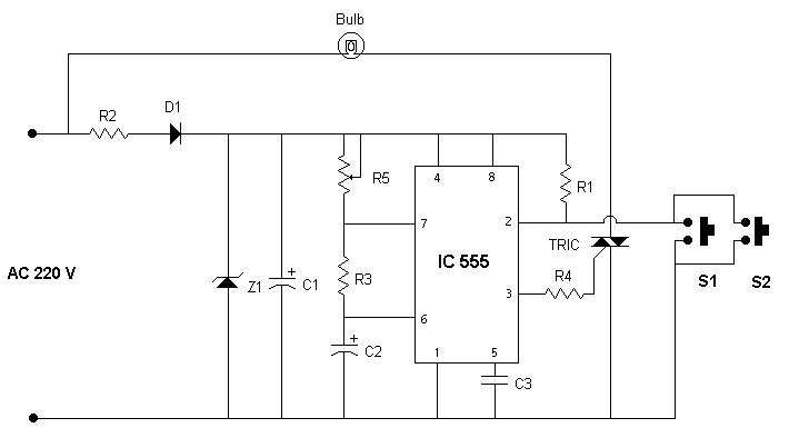
Components Required
- Resistors
- R1, R3 ( 10Kilo ohms)
- R2 (10K kilo ohms / 10W)
- R4 (220 ohms)
- R5 (1Mega ohms)
- Integrated circuit
- IC 555
- TRIC
- TRIC (BT136)
- Diode
- D1 (IN 4001
- Z1 ( 12V Zener diode)
- Capacitor
- C1 (1000 mfd /25V)
- C2 (200 mfd/ 16V
- C3 (0.1 mfd)
- Miscellaneous
- Push to on switch (S1, S2)
- Bulb (220V/ 60W)
- PCB or Breadboard
- Flexible Wire
- Soldering rod etc..
Principle and Working
Good thing about this circuit is that the user needs to push the button only ones : To turn the light on. The light will turn automatically OFF after some time, since the switching OFF mechanism is timer based. Also note that the "push to on" switch is used here, this should be momentarily pushed to turn the light on.
When "push to on" switch is pushed, pin-2 gets a negative pulse, and the timer gets triggered. Due to this C2 connected with pin-6 and pin7 starts charging slowly. After some time, when the voltage across C2 goes above 2/3 Vcc, the timer stops working and the light turns OFF automatically. Duration for which the light will be ON depends upon the R5 value. The Zener diode Z1 and C1 combination is used here to provide constant 12V DC for IC-555. Diode D1 is used so that the capacitor C1(providing power to the IC) gets only positive cycle for charging.
Automatic Staircase Light 2
Circuit Diagram

Components Required
- Resistors
- R1 (2 Mega ohms, 1/2W)
- R2 (820 Kilo ohms, 1/2W)
- Integrated circuit
- IC1(741)
- Relay
- RL1 (9V/ 300 ohms)
- Capacitor
- C1 (10 mfd / 16V)
- Miscellaneous
- Push to on switch (S1, S2)
- Bulb( 9V/ 40mA)
- PCB or Breadboard
- Battery 9V
- Flexible Wire
- Soldering rod etc..
Principle and Working
This is also a push-to-on, and auto-OFF circuit. User needs to push the button only ones : To turn the light on. The light will turn automatically OFF after some time, since the switching OFF mechanism is timer based. Also note that the "push to on" switch is used here, this should be momentarily pushed to turn the light on.
When the button is pushed, relay gets triggered and charges capacitor C1. After release, the capacitor starts discharging through resistor R1. Since the R1 is of large value, C1 takes some time to get discharge. After C1's discharge relays turns off automatically. Good thing about this circuit is that, the circuit doesn't consume any power when it is not being used. This saves energy and increases battery life.
Clack Clack Electronic Bell
Circuit Diagram

Components Required
- Resistors
- R1 (100 ohms , 1/2W)
- R2 (470 ohms , 1/2W)
- Transistors
- T1 (AC126)
- T2 (LS100)
- Capacitors
- C1 (0.22 mfd, 50V)
- C2 (0.22 mfd, 50V)
- Preset
- Vr1 (2 mega ohms)
- Miscellaneous
- Battery 6V or Dry cell (6 x 1.5)
- LS ( Loudspeaker, 8 ohms, 6 cm diameter)
- S1 ( Slide switch, single pole)
- TR1 (Transformer)
- PCB or Breadboard
- Flexible Wire
- Soldering rod etc..
Principle and Working
This is a very simple electronic bell. Here the transistor TR-1 acts as a low frequency oscillator. Transistor TR1 also acts as a pre-amplifier. Oscillations generated from TR-1 is fed to the transistor TR2 which is a small audio amplifier. Preset Vr1 can be used to vary frequency, which will change the output tone of the bell.
Electronic Astrologer
Circuit Diagram

Components Required
- Resistors
- R1 (1kilo ohms, 1/2W)
- R2 ( 18 Kilo ohms, 1/2W)
- R3 (100 ohms, 1/2W)
- Integrated Circuit
- IC7400
- Preset
- VR1 (1 kilo ohms)
- VR1 (1 kilo ohms)
- Capacitor
- C1 (3 mfd , 10V)
- C2 (100 mfd, 10V)
- LED
- LED1 ( 3V)
- LED2 ( 3V)
- Miscellaneous
- S1 Push-to-on switch (single pole)
- S2 Toggle switch
- Battery 6V
- PCB or Breadboard
- Flexible Wire
- Soldering rod etc..
Principle and Working
This electronic astrologer answers in either YES or NO. For this reason it is a good idea to put this circuit in a box, and mark one LED as YES, and another as NO. Electronic astrologer can played like this :- You ask such question whose answer can be either YES or NO, e.g Is it going to rain today ?. Now, press and release push-button(S1) to get the answer. After release, the glowing LED is electronic astrologer's answer.
Now lets see how it works! In this circuit IC-7400 is used as multi vibrator. When button S1 is pressed, multi-vibrator starts working, and a low voltage toggles between pin 6 and 8 at very fast rate. As the button is released, low voltage gets latched to any of the pins- 6 or 8. This low voltage provides drain path to the LED connected to it, and that LED glows. This glowing LED becomes astrologer's answer. Note that chanced for each LED to glow is 50%.
Electronic Dice
Circuit Diagram

Components Required
- Resistors
- R1 (22 kilo ohms, 1/2W)
- R2 (12 kilo ohms, 1/2W)
- Integrated Circuit
- IC1 (555)
- IC2 (CD4017)
- Capacitor
- C1 (0.022mfd, 50V)
- LED
- 6 LEDs
- Miscellaneous
- S1 Push-to-on switch (single pole)
- S2 Toggle switch
- Battery 9V
- PCB or Breadboard
- Flexible Wire
- Soldering rod etc..
Principle and Working
It is good idea to put this circuit in a box and mark/write each LED with number 1 to 6. Now, when switch S1 is pushed momentarily, any one of the 6 LEDs will glow. The Number marked for glowing LED becomes dice's output. Every time S1 is released, new LED will glow randomly. Chances for each LED to glow is 16.66%.
This circuit makes use of two ICs, IC555 and IC-CD4017. IC-555 is used as square wave generator, and IC(CD4017) as a counter. Actually CD4017 is a divide-by-10 johnson-counter with 10 decoded outputs. IC555 simply generates clock for CD4017, and the clock frequency is controlled by R1 and C1. Counter CD4017 starts counting from 0 to 9 by putting high voltage on each of the 10 pins (one after another). The High voltage shifts from one pin to another on every positive edge of the clock. Since, in our circuit pin-5 is shorted with pin-15(reset), the counter gets reset after reaching 6, and again starts from 0. Now, when S1 is pushed, IC555 generates clock for CD4017. This clock enables CD4017 to count from 0 to 6 by putting high voltage on each of the 6 pins (one after another). These 6 pins are connected to 6 respective LEDs. When S1 is released, high voltage gets latched to any one of the 6 pins, and this becomes output of the DICE.
Light Operated Switch
Circuit Diagram

Components Required
- Resistors
- VR1 (47 Kilo ohms Variable resistance)
- Transistors
- T1 (BC108)
- Miscellaneous
- Battery 9V DC
- LDR
- Relay (6V /300 Ohms)
- Bulb (230V /60W)
- PCB or Breadboard
- Flexible Wire
- Soldering rod etc..
Principle and Working
The circuit above shows a simple application of light operated switch. This circuit senses the ambience light and depending on the presence/absense of sufficient ambience light, it turnes the bulb On/Off automatically. The bulb gets on when there is insufficient ambience light (e.g evening or night time) and switches off automatically when enough ambience light is present. (e.g In day time, when the sun light is present additional light may not be needed.) This bulb can also be your street lamp that needs to be switched on every evening, and switched off every morning. The circuit does this job automatically without any manual interference.
Lets See how this works :- During day time when sunlight falls on LDR, the resistance of LDR decreases. The decrement of resistance causes more potential across VR1 and very less potential across LDR. The potential across LDR is directly fed to the base of transistor TR1 (shown in circuit). Because of the low potential difference across TR1's base and emitter, the transistor TR1 goes into cutoff, and restricts any flow of current from collector to emitter. This non availability of sufficient current causes the relay to get de-magnetized and switches off any device attached to it (bulb in this case). Similarly when sunlight is not present (i.e. at night), the resistance of LDR increases and hence the potential across LDR also increases. The increased potential causes transistor to move from cutoff to saturation, allowing maximum current to pass from collector to emitter. The increased current turns the relay ON and also the bulb attached to it.
Mini Tester
Circuit Diagram

Components Required
- Resistors
- R1 (68 kilo ohms , 1/2W)
- R2 (330 kilo ohms , 1/2W)
- R3 (1 kilo ohms, 1/2W)
- R4 (680 ohms, 1/2W)
- R5 (22 ohms, 1/2W)
- Transistors
- T1 (BC107)
- T2 (AC128 or AC188)
- LED
- LED1
- Miscellaneous
- Battery, Dry cell 6V
- (L1, L2) Testing probes or crocodile clips
- S1 ( Slide switch, single pole)
- PCB or Breadboard
- Flexible Wire
- Soldering rod etc..
Principle and Working
This is a very useful circuit which can be used for testing electronic component. Like multimeter one can use this circuit for :- continuity testing, resistor testing, capacitor testing and diode testing.
In this circuit LED glows only when probes L1 and L2 are short-circuited or has a path for the current to flow. This fact will be used to test components.
Continuity Testing : Connect the two probes to the points between which the continuity has to be tested. If the LED glows! the points are electrically continuous otherwise not.
Resistor Testing : This circuit can test upto 10K resistors. If LED glows, resistor is good otherwise faulty.
Capacitor Testing : When a electrolytic capacitors is put in between L1 and L2 the LED should show glow momentarily. If the LED glows continuous, the capacitor is defective.
Diode Testing : A good diode will produce a glow in one direction only. If a diode produced glow in both directions, or in none of the direction, diode is faulty.
Transformer coil Testing : A good transformer winding should glow LED, but in case of "open circuited" faulty coil, the LED won't glow.
Musical Electronic Bell
Circuit Diagram

Components Required
- Resistors
- R1 (330 ohms 1/2W)
- R2 (8.2 Kilo ohms 1/2W)
- Capacitor
- C1 (500mf/ 16V)
- C2 (0.01mf/ 50V)
- Transistor
- T1 (BC148B)
- T2 (AC128)
- Diode
- D1 (BY125)
- Transformer
- TR1 (230V to 6v step down, 200mA )
- Miscellaneous
- Speaker (8 ohms)
- Neon lamp
- Pushbutton (S1)
- PCB or Breadboard
- Flexible wires
- Soldering rod etc..
Principle and Working
This is a very simple musical electronic bell. This bell not only gets you rid from old irritating noisy bells, but also avoids unwanted disturbances on radio and TV produced by damp waves. These damp waves are generated by electrical devices when they are switched on or off.
In this circuit when the push-button(S1) is pushed, current starts flowing through the transformer. This transformer is a step-down transformer which converts 230V AC to 16V AC. The stepped down voltage is passed through diode D1. Diode D1 behaves as a half wave rectifier and passes only positive voltage. This positive voltage is used to charge capacitor C1. The Charged capacitor C1 acts as a power source for low frequency oscillator. Transistor T1 and T2 are connected in such a way that they constitute a low frequency oscillator of 1 kHz. This oscillating voltage generates oscillating current which flows through the speaker, and generates a sweet tone. The pitch of the generated tone can be changed by using different values of R2 or by using preset of 10K ohms in place of R2.
MW Transmitter
Circuit Diagram

Components Required
- Resistors
- R1 (68 kilo ohms , 1/2W)
- R2 (82 ohms , 1/2W)
- Transistors
- T1 (BF194)
- Capacitors
- C1 (0.22 mfd, 50V)
- C2 (0.005 mfd, 50V)
- Gang capacitor
- G1 (2x type)
- Ferrite rod
- FR1 (15 cm long, 8 mm diameter)
- Antenna
- At1 (Antenna coil of medium wave radio receiver )
- Miscellaneous
- Battery, Dry cell 6V
- LS ( Loudspeaker, 8 ohms, 6 cm diameter)
- S1 ( Slide switch, single pole)
- Radio receiver ( for testing)
- PCB or Breadboard
- Flexible Wire
- Soldering rod etc..
Principle and Working
This transmitter can be used as an inter-room radio telephone. The communication range of this transmitter is 5 meters only, but the range can be increased to 10-12 meters by installing a 2.5m long antenna horizontally at a height of about 3 meters.
The transmitter begins to work when S1 is switched on. The audio of this transmitter can be heard on a MW band domestic radio receiver placed at some distance. The audio can be heard any where between 1200 to 1600 kHz range. The frequency of the transmitter can be adjusted by gang capacitor to get clear reception, and to change the transmission frequency.
NiCd Cell Charger
Circuit Diagram

Components Required
- Resistors
- R1, R2 (100 ohms)
- R3, R5, R7, R9 (12 ohms / 1W)
- R4, R6, R8, R10 (220 ohms)
- R11 (470 ohms)
- Integrated circuit
- IC1 (7808)
- Transistor
- T1 (BC547)
- T2, T3, T4, T5 ( BD160)
- Transformer
- TR (0-12 /1A)
- Preset
- VR1, VR2 (10K)
- Diode
- D1, D2, D3, D4 (IN4148)
- D5, D6, D7, D8 (IN4007)
- Capacitor
- C1, C2 (0.1mfd)
- C3 (1000mfd/ 16V)
- Miscellaneous
- Fuse ( 50 mA)
- Cell holder
- On-Off switch
- One Pole Three Way Switch
- PCB or Breadboard
- Flexible Wire
- Soldering rod etc..
Principle and Working
The project of cell charger shown here uses IC(7808) and transistor (BC547B). The transformer TR1 is a step down transformer, and steps down 230V AC voltage to 12V AC. This 12V AC is fed to the rectifier bridge. Four IN4001 diodes constitutes the rectifier circuit. The rectifier and IC7808 together converts 12V AC to 8V DC. Transistor T1(BC574) is used as a voltage regulator. Three current selection through switch S1 can be made to select different charging current (90mA, 180mA and 300 mA). If you want to charge cell very fast, 300mA charging current should be selected, this can charge cell with-in 30 minuets. LEDs, LED1 to LED4 are charging indicator,these LEDs glows only when the cell is placed for charging. In this circuit Transistor T2, T3, T4, T5 constitutes a constant current source which charges cadmium cell.
Simple Traffic Light Controller
Circuit Diagram
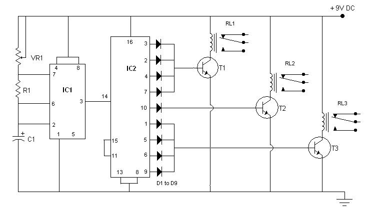
Components Required
- Integrated Circuit
- IC-1 (555)
- IC-2 (CD4017)
- Resistors
- R1 (10K)
- VR1 (100K)
- Capacitor
- C1 (100mfd/ 16V)
- Diode
- D1-D9 (IN4007)
- Transistor
- T1 (BC148)
- T2 (BC148)
- T3 (BC148)
- Miscellaneous
- Three Relays
- Battery (9V DC)
- Neon lamp
- Flexible wires
- Soldering rod etc..
Principle and Working
This circuit is self explanatory by its name, and can be used to control traffic in public places, or to demonstrate traffic rules in traffic-parks. IC2, which is heart of the circuit, is a decade counter. In this counter for every pulse fed to pin-14, potential keeps shifting from D1 to D9 in cyclic order. IC1 is used as a pulse generator and generates pulses in regular configurable intervals. These intervals can be changed by varying VR1. The circuit is designed in such a way that out of nine pulses, relay RL1 remains triggered for 4 pulses, relay RL2 for 1 pulse and relay RL3 for remaining 4 pulses. Since D1-D4 provide current to T1, T1 is on whenever there is potential on any diode D1 to D4, which keeps relay RL1 triggered. Similarly other diodes are responsible for RL2 and RL3 triggering. Red, Yellow and Green lamps can be connected to the relays RL1, RL2 and RL3 respectively to complete your mini traffic light controller.
Voice Amplifier
Circuit Diagram
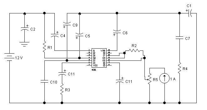
Components Required
- ICs
- IC1 TBA810
- Resistors
- R1 (100 ohms)
- R2 (2.2 ohms)
- R3 (56 ohms)
- R4 (100 Kilo ohms)
- R5 Volume Controller (1M)
- Capacitors
- C1 (1000 uF /16V)
- C2 (1000 uF /16V)
- C3 (470 uF /16V)
- C4 (220 uF /16V)
- C5 (220 uF /16V)
- C6 (220 uF /16V)
- C7 (0.01 uF)
- C8 (0.047 uF)
- C9 (1.5K )
- C10 (5.6 K)
- C11 (100 uF /16V)
- Others
- Speaker (LS 8 ohms)
- power supply ( 12V DC, 750mA)
- Flexible wires
- PCB or breadboard
- Soldering rod etc..
Principle and Working
This is a very simple and low cost audio amplifier. Small modification in this circuit can be done to use along with walkman and intercom etc.
TBA810 is heart of the circuit, which is a very powerful audio amplifier. Because of its easy availability and low cost, this IC can be seen in many gadgets. TBA810 has 12 pins, out of which pin-1 and pin-4 are are connected to positive supply, pin-9 and pin-10 are grounded. Pin-8 is used as input, and pin-12 as output. The amplified signal from pin-12 is given to Loud-speaker(LS) through capacitor(C1). The strength of the amplified signal can be controlled by controlling the intensity of the input signal. Input signal strength is controlled by the potentiometer R5 (volume control).
Pocket Transmitter
Circuit Diagram
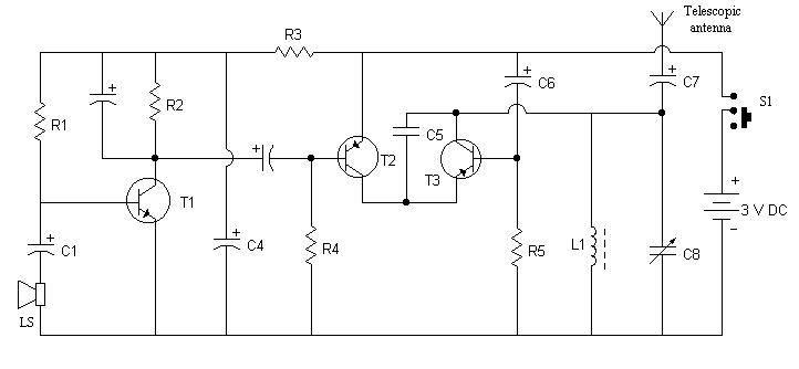
Components Required
- Resistors
- R1 (220 kilo ohms)
- R2 (4.7 kilo ohms)
- R3 (3.3 kilo ohms)
- R4 (39 kilo ohms)
- R5 (68 kilo ohms)
- Transistor
- T1 (BC148)
- T2 (2N363)
- T3 (2N481)
- Capacitor
- C1, C3, C6 (10 mfd, 6V, electrolytic)
- C2 ( 30 mfd, 6V, electrolytic)
- C4, C7 (100 mfd, 6V, electrolytic)
- C5 (120 mfd, 50V, ceramic)
- C8 (4-70 pf, Trimmer)
- Miscellaneous
- L1 (Oscillator coil of MW radio receiver)
- S1 (Slide switch, single pole)
- LS (Loudspeaker, 8 ohms, 6cm dia)
- Battery (3V or 1.5 x 2 cells)
- PCB or Breadboard
- Flexible Wire
- Soldering rod etc..
Principle and Working
This is a very simple circuit, which works on two 1.5V pencil cell. With a telescopic antenna this transmitter can cover 20 to 25 meters.
In this circuit loud-speaker(LS) is used as a microphone to convert sound wave into audio signal. Transistor BC148 works as an audio amplifier, and Transistor 2N481 works as radio frequency oscillator. The transistor 2N363 modulates the audio signal to the carrier radio frequency, produced by the oscillator. The modulated signal is then transmitted to air by telescopic antenna.
This transmission can be listen on any radio receiver by adjusting receiver's frequency. For clear reception, the receiver's and the transmitter's frequency should be same. The transmission frequency of the transmitter can be changed by rotating oscillator coil's core and trimmer's screw.
Reflex Action Game
Circuit Diagram

Components Required
- Resistors
- R1, R2 (470 ohms, 1/2W , carbon)
- Transistor
- T1, T2 (AC128 or AC188)
- Lamps
- L1 (6V, 60 mA)
- L2 (6V, 60 mA)
- Miscellaneous
- S1 Push-to-on switch (single pole)
- S2 Push-to-on switch (single pole)
- S3 Toggle switch
- Battery 6V or 1.5 x 4 cells
- PCB or Breadboard
- Flexible Wire
- Soldering rod etc..
Principle and Working
This is a very interesting and simple circuit. This also can be used in quiz events, where two participants hit their button to answer. The participant, who pressed his button first, will get a chance to answer first. This circuit will resolve which participant hit the button first, by glowing the lamps associated with the button.
When S3 is in ON position, base circuits of both the transistors remains open and thus no current flows in their respective collector-emitter circuits. Hence, both the lamps remain off.
Now, let S1 be pressed first, the transistor TR1 gets negative base voltage through R1. Due to this transistor TR1 starts conduction, and lamp L1 begins to glow. On account of this action the voltage at point P drops to nearly zero value and if the push-button S2 is pressed in this condition , the transistor TR2 gets no base voltage and it will remain non-conduction.
Now, let S1 be pressed first, the transistor TR1 gets negative base voltage through R1. Due to this transistor TR1 starts conduction, and lamp L1 begins to glow. On account of this action the voltage at point P drops to nearly zero value and if the push-button S2 is pressed in this condition , the transistor TR2 gets no base voltage and it will remain non-conduction.
Similarly when S1 is pressed first, the lamp(L2) associated with S1 will glow preventing L1 to glow. Since, at a time only one lamp will glow, this circuit will always give correct judgment.
TRIAC Switch To Control High-Voltage Devices
Circuit Diagram
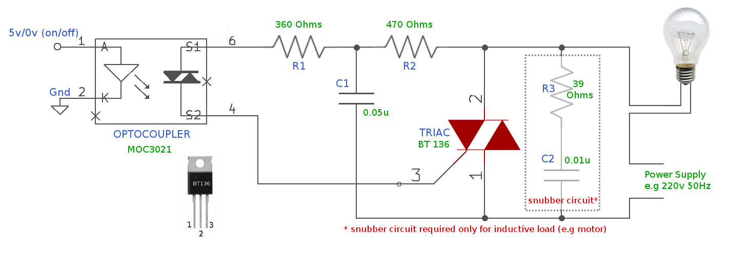
Components Required
- Resistors
- R1 (360 Ohms, 1W)
- R2 (470 Ohms, 1W)
- R3 (39 Ohms, 1W, optional : only for inductive load)
- Capacitor
- C1 (0.05uF, 400V, non electrolytic)
- C2 (0.01uF, 400V, non electrolytic, optional : only for inductive load)
- TRIAC
- TRIAC (BT136)
- Integrated Circuit
- IC1 MOC3021 (OPTO-COUPLER)
- Miscellaneous
- 220v bulb as load
- PCB or Breadboard
- Flexible Wire
- Soldering rod etc..
Principle and Working
From ages electron-magnetic relays are being used as switches to control high voltage devices. But, because of their bulky size and noise (both electrical and mechanical) people started using TRIAC with opto-coupler as better alternative.
Above circuit uses TRAIC and Opto-coupler to use small voltage to control high voltage devices. For example, micro-controller to control 220v bulb or any device which runs on high voltage.
ON Condition :
When 5v is applied to pin 1 & 2 of the opto-coupler (MOC3021), pin 6 & 4 gets connected internally(Within opto-coupler) and allows current to flow between them. This connection provides GATE current to the TRIAC (TRIAC pin 3) and TRIAC starts conducting the main current between pin 2 & 1, which completes the circuit and makes bulb to glow.
When 5v is applied to pin 1 & 2 of the opto-coupler (MOC3021), pin 6 & 4 gets connected internally(Within opto-coupler) and allows current to flow between them. This connection provides GATE current to the TRIAC (TRIAC pin 3) and TRIAC starts conducting the main current between pin 2 & 1, which completes the circuit and makes bulb to glow.
OFF Condition :
Now, when 0V is applied to opto-coupler, opto-coupler makes pin 6 & 4 electrically opened and doesn't allow any current to flow between them, as a result it stops the GATE current to TRIAC and the main current between pin 2 & 1 also stops, which finally turns off the bulb.
Both type of devices working on AC and DC can be controlled using this switch, provided proper power supply is used for them
Important to note that the mentioned snubber circuit is only required if your load is inductive (like motor etc..). For non inductive loads you can just remove C2 & R3 from your circuit and leave it open.
It is important to select proper current rating TRIAC, above circuit may support device which draws upto 4A of current.
Benefits of this circuit
- Very low voltage 3V to 5V can be used to control load device.
- Opto-Coupler maintains separation between high voltage and low voltage circuitry and never allows high voltage to flow back to micro-controller making it safe.
- No mechanical noise.
- Compact, occupies less volume on PCB.
- Can be used for fast switching, electromagnetic relays cannot due to mechanical make/break.
Laser Pointer Triggered On/Off Switch
Remote control is commonly performed with either modulated infrared emitters or radio-frequency wireless transmitters. During a boring presentation, it occurred to me that the presenter could control a slide show by aiming their laser pointer at a list of commands with bullet-point targets. Alternatively, someone lying in bed could set the clock alarm/snooze (across the room) or turn off lights by simply aiming the laser dot at the correct spot on the desired object. This would eliminate the need to have special remotes for each manufacturer.

Left: Controlling a presentation with a laser pointer. Right: Turning on/off an alarm clock or lamp from bed.
This article demonstrates a simple circuit with two off-the-shelf logic chips to allow a laser to turn on and off an LED. Obviously, the electronics would need to be expanded to control an appliance or support additional sensors. However, this example project is perfectly functional for controlling a low-voltage DC device, such as starting a robot.
Video of Laser Pointer Control Circuit
Before diving into the schematic, it might be best to demonstrate the circuit in action with a video. Don’t worry if you don’t understand exactly how it works based on the audio commentary.
Schematic of the Laser Pointer Sensor
The full circuit is divided into two parts for learning purposes:
- Detecting a laser aimed at either the “on” or “off” sensors.
- Setting the correct output state, and keeping that state even after the laser pointer is turned off.
Here is the first wiring diagram that handles laser detection:

A schematic showing two sensors, two trimpots, and a TI TLV3702 comparator chip.
IC1 is a comparator chip that compares the voltage across R2 (a light sensor) to the voltage across R22 (a potentiometer). When the laser hits R2, the sensor’s resistance drops, which causes the voltage across it to drop. When the laser is not targeting R2, the sensor’s resistance increases (to normal) and the voltage follows.
If the voltage of R2 is lower than R22, then the comparator chip pin 1 outputs low (0 V). If the voltage of R2 is higher than R22, then the comparator chip pin 1 outputs high (5 V). Incidentally, if you wanted the opposite result, you could just swap the inputs to pins 2 and 3.
Independently of that, IC1 also performs this voltage comparison task for the other light sensor (R1) and the other potentiometer (R12). As you can imagine, a larger comparator chip would allow more sensors to be monitored.
The potentiometers (R12 and R22) are adjustable to set the detection trip level. If ambient room lighting seems to be setting off a sensor errantly, then the voltage trip level can be lowered by rotating the screw or dial on the associated potentiometer. Conversely, if the light from a well-aimed laser isn’t being detected by the target sensor, then the voltage trip level can be raised by rotating the screw or dial in the opposite direction. Having two potentiometers allows a custom trip point for each sensor.
Both outputs of the comparator chip flow into the next circuit (which we'll discuss later in the article).
For debugging purposes, LED1 and LED2 are connected to the outputs to turn on when the laser hits the associated sensor. Unfortunately, the TLV3702 comparator chip is not designed to deliver enough output current to control an LED directly. To compensate, I’ve selected a pair of high-efficiency, ultra-bright LEDs and fairly high resistor values (2200 ohms).
If you choose poor-quality LEDs, then you won’t see them light up. If you install standard LED resistors (330 ohms), then the outputs won’t be able to successfully communicate with the next circuit.
Sneaky Series Sensors Split Svoltage
This circuit includes an auto-brightness feature. As you can see in the schematic, R1 and R2 are connected together (ignore R3 for the moment). This forces them to constantly divide the 5 V between them.
When the room is dark, assume R1=100000 ohm and R2=100000 ohm. Since they are equal, they both get 2.5 V (equally split 5 V). When the room is light, assume R1=500 ohm and R2=500 ohm. Again, since they are equal, the both get 2.5 V (equally split 5 V). In the example cases, the voltage is always 2.5. The room brightness does not affect the voltage readings!
Compare that situation to when sensors are connected to their own voltage sources (putting them in parallel). When the room is dark, they will both have high resistances and receive most of their 5V source, say 4.9V. When the room is bright, they will both have low resistances and receive little of their 5V source, say 0.1V. Because they aren’t sharing/splitting/dividing the voltage between them, their voltage changes from 0.1V to 4.9V based on the room lighting, instead of a steady 2.5V.
Forcing the sensors to share the same voltage source (putting them in series) means the only time their voltages differ is when one receives a different amount of light than the other. This occurs when one sensor is targeted by the bright laser. Pitting the sensors against each other changes the circuit from an absolute light measurement to a relative light measurement.
What about R3?
R3 is a fixed resistor that prevents too much current from passing through the sensors in the event the room is very well lit or some jerk aims a powerful laser at both sensors. For example, if both R1 and R2 were only 10 ohms, then 250 mA would pass through the sensors.
Furthermore, R3 saves power because it lowers the idle current to less than 5 mA. This isn’t a perfect solution though, as R3 also competes with the sensors for voltage, meaning it will cause detection errors under very bright conditions.
R3 is a fixed resistor that prevents too much current from passing through the sensors in the event the room is very well lit or some jerk aims a powerful laser at both sensors. For example, if both R1 and R2 were only 10 ohms, then 250 mA would pass through the sensors.
5V / (10Ω + 10Ω) = 0.250 AIn this type of configuration, the resistor is called a “current limiter”. Think of R3 as an emergency brake.Furthermore, R3 saves power because it lowers the idle current to less than 5 mA. This isn’t a perfect solution though, as R3 also competes with the sensors for voltage, meaning it will cause detection errors under very bright conditions.
Why a Texas Instruments TLV3702 Comparator?
This circuit won’t work with old-fashioned comparators for two reasons.
Reason #1: Needs Full Input Range
Sensor R1, potentiometer R12, and the comparator are all connected to 5V. Therefore, the comparator needs to be able to measure voltages up to 5V. Sadly, older comparators could not make comparisons in the top 1.5V of their supply voltage (which would limit the inputs to 5V - 1.5V = 3.5V in that case).
Newer comparators that overcome this limitation are said to have “rail to rail” inputs. That is, they can do comparisons on voltages from the low rail (0V) to the high rail (5V or whatever the comparator supply is).
Reason #2: Needs to Output Both Low and High
Another characteristic of older comparators was an open collector output. This meant that they could only produce either 0V or disconnected on their output. You were required to include a pull-up resistor to convert the disconnected state into the desired voltage for a “high” state. Believe it or not, this was an intentional feature that allowed a comparator with 16V power supply (or whatever) to connect to logic-level voltages (such as 3.3V or 5V).
Newer comparators are available with either open collectors (needs a resistor) or push-pull (no resistor needed). The TLV3702 has push-pull outputs, eliminating the need for additional resistors in this circuit.
Although not relevant to the laser circuit, the TLV3702 has many other fine features. Such as:
- Low power usage (less than a microamp)
- Low input current (less than a nanoamp)
- Can handle noisy inputs above or below rail (better than rail-to-rail tolerance)
- More sensitive / greater resolution
- Available in pine or lemon scent
These features come at a cost. The TLV3702 costs $2.25, whereas the classic old LM393 (used in Sandwich) costs $0.39.
Now that we know how to detect when a laser hits a sensor, let’s see how we remember that state when the laser is turned off or aimed away.
2. Remembering Sensor State with a Flip-Flop Latch 1-bit Memory Chip
At this point, the laser-pointer detection circuitry is able to determine when a laser light is aimed at a particular photosensor. If the laser is aimed at the top sensor, the comparator chip outputs “on”. If the laser is aimed at the bottom sensor, the comparator chip outputs “off”.
The circuit could be considered complete if you wanted something to be turned on only while the laser is aimed at the on sensor. However, if you want the circuit to remember whether the “on” sensor or the “off” sensor was most recently selected, then you’re going to need to hook those outputs to a memory chip.
Looking back at the schematic, you'll notice that the output names of “on” and “off” have little lines above the words. Usually an output is high (5V) when a condition is true, but the line above the word means the output is low (0V) when the condition is true. The line stands for “opposite”, “not”, or “negate”.
The reason that the comparator has been wired to do this is because the memory chip on this page needs the information in that format. However, should you have a circuit that needs normal outputs, simple swap IC1 pin 5 with IC1 pin 6, and IC1 pin 2 with IC1 pin 3. Flipping the input pins on the comparator provides the opposite output.
The reason that the comparator has been wired to do this is because the memory chip on this page needs the information in that format. However, should you have a circuit that needs normal outputs, simple swap IC1 pin 5 with IC1 pin 6, and IC1 pin 2 with IC1 pin 3. Flipping the input pins on the comparator provides the opposite output.
Single Bit Memory
This circuit only needs to remember whether the final output should be on (5V) or off (0V). This is the smallest, most rudimentary amount of memory. It is called a “bit”; which stands for “binary digit”. A bit can only be on or off.
The 7474 chip is a basic logic chip that contains a 1-bit memory cell. For convenience, just like the comparator chip on the previous page, the 7474 includes two independent copies of this feature on a single chip. Therefore, the 7474 has two independent 1-bit memories on the chip.
We only need one bit for this circuit, so the top half of the schematic shows one side of the chip is unused. Tying those unused inputs to 5V prevents them from receiving random noise. (Don’t tie those pins to ground, because pins 10 and 13 on the 7474 chip aren’t logically permitted to be 0V at the same time).

A 74AC74 D-type flip-flop 1-bit memory remembering a comparator output to control a blue LED.
This circuit is incredibly straightforward. “On” is connected to the set pin. “Off” is connected to the clear pin.
If the “on” sensor output is low, it sets (pin 4) the IC2 output (pin 5) to high. A high output (5V) will provide power to the big blue LED (LED3). The blue LED is prevented from receiving too much current by a resistor (R30).
If the “off” sensor output is low, it clears (pin 1) the IC2 output (pin 5) to low. Because the output is low (0V) and the other end of the LED-resistor pair is also low (connected to GND which is 0V), no current flows. LEDs only light up when current flows through them. Therefore, the LED doesn’t light up.
The purpose of the 74AC74 chip is to remember whether it was last set or cleared. The other pins are not used in this circuit, but provide fancier memory techniques such as remembering the data input (pin 2) only when the clock (pin 3) goes from low to high. By the way, this configuration of the chip is technically considered an SR latch (set-reset), as opposed to a full D-type flip-flop.
Besides remembering the last state, the other valuable service this chip performs is outputting greater current than the comparator chip can. In fact, this 74AC74 chip is rated at 24mA @ 4V when the chip is connected to a 5V supply. That’s plenty for an LED.
What’s with the Extra Letters on Part Number?
The exact chip I selected is a Texas Instruments SN74AC74N. It has the standard 7474 pin layout and functionality. The extra letters provide a little more specific information.
Chip manufacturers include letter prefixes to indicate that it came from their company. In this case, “SN” is the brand manufactured by Texas Instruments.
Chip manufacturers include letter suffixes to indicate the type of package, guaranteed temperature range, legal compliance (hazardous materials), and whether it comes on a reel. In this case, the letter “N” at the end of the Texas Instruments part name says that it comes on a plastic DIP chip that is the right size for a solderless breadboard. If you order this same chip with the letter “D” at the end, it will be a smaller surface-mount chip (SOIC) that is better suited for automated placement on a printed circuit board.
For our purposes, the middle letters are the most critical. The middle letters specify the semiconductor technology used to implement this 7474 functionality. “AC” stands for “Advanced CMOS”. When an engineer sees "AC", he or she knows the voltage range, speed, noise emitted, and current output. None of that says what the chip does, only the conditions under which it performs.
There is a whole variety of semiconductor technologies for this chip available today: 74S74, 74LS74, 74C74, 74HC74, 74HCT74, 74VHC74, 74ACT74, 74AC74, and so on. Because they use different voltages and have differing characteristics, you usually cannot interchange them in a circuit. That is, if you tried to put a 74LS74 into this circuit, the LED would not light up, because the LS doesn’t provide enough output current. Furthermore, the 74LS74 requires a low input to be no more than 0.8V, which is difficult to achieve while the debugging LEDs are connected to the comparator outputs.
Long story short, buy the exact manufacturer’s part number SN74AC74N
Bypass/Decoupling Capacitors
In the descriptions of both schematics, I skipped over the capacitors labeled C1 and C2.
C1 and C2 are ordinary 0.1-microfarad capacitors that provide local power storage for a circuit. It is common to include one small capacitor per chip to reduce circuit noise and to eliminate logic glitches.
In reality, the reduced power usage and decreased noise of newer chips makes this less necessary than in years past. However, because hobbyists often use noisy circuit layouts, and because these capacitors are so inexpensive when compared to a hobbyist’s free time that would be spent diagnosing a noise glitch, I still highly recommend sprinkling capacitors liberally near the power pins on chips.
That leads us to actually building the entire circuit on a solderless breadboard...
3. Building the Laser Detector on a Solderless Breadboard
We first learned how a comparator detects a laser aimed at a sensor by the drop in voltage. Then, we learned how a 7474 flip-flop chip can remember which sensor was triggered last. Finally, here is the combined circuit laid out on a breadboard.

Laser-pointer remote control on a solderless breadboard.
I use multiturn trimpots for R12 and R22 rather than single turn trimpots. It probably isn’t necessary, although I prefer the ultra fine-tuning that multiturns allow.
If you have any problems with the circuit, it is helpful to try measuring the voltages at each of the pins of the comparator (the smaller 8-pin chip). From pin 1 (lower left) to pin 8, you should see:
- Lower-sensor comparison result: 0V-1V laser detected, 1V-4V LEDs using too much power, or 4V-5V laser not detected.
- Lower potentiometer: <0.25V trip point too low, 0.25-1V good trip point, or >1V trip point too high.
- Lower-sensor voltage: <1V laser aimed at lower sensor or finger on upper sensor. >1V dark room or laser aimed at upper sensor.
- Ground: 0V good. >0.05V something wrong with power supply or voltmeter hookup.
- Upper potentiometer: <4V trip point too low, 4V-4.75V good trip point, or >4.75V trip point too high.
- Upper-sensor voltage: <4V dark room or laser aimed at lower sensor. >4V laser aimed at upper sensor or finger on lower sensor.
- Upper-sensor comparison result: 0V-1V laser detected, 1V-4V LEDs using too much power, or 4V-5V laser not detected.
- Vcc: <4.75V something wrong with power supply, 4.75V-5.25V good, or >5.25V something wrong with power supply.
In addition, if you happen to measure the total circuit consumption when the LEDs are off, it should be less than 5 mA. Mine is approximately 1.7 mA -- almost all of it consumed by the photoresistors (R1 and R2).
Beyond Outputting to an LED
As presented, the final output is to turn on a large blue LED. However, this could easily be modified to connect to an existing pushbutton to act as though the user pushed it. Most pushbuttons generate a 0V output when pressed. Simply connect IC2 (74AC74) pin 6 to the output pin on the pushbutton.
To actually power an entire circuit, rather than a single LED, the output pin 5 could be wired to an NPN power bipolar junction or N-channel power MOSFET transistor. The controlled circuit’s ground would connect to the top of the transistor. The bottom of the transistor and the controlled circuit’s power supply ground would connect to the ground of the laser sensor circuit.
When the laser hits the on sensor, the transistor would turn on and provide the ground connection for the controlled circuit. When the laser hits the off sensor, the transistor would turn off and the controlled circuit would be disconnected from one end of the power supply, shutting it off just like a power switch.
We have a lot of flexibility because the 7474 chip provides both a normal output (pin 5) and an opposite output (pin 6). So, if a controlled circuit wants a low voltage to turn it on, connect it to pin 6. Otherwise, connect it to pin 5.
(For safety reasons, this article won’t discuss the topic of controlling an AC device like a lamp. However, generally you’d use a properly rated relay.)
Microcontroller Superiority
A single microcontroller ($1.40 when purchased one at a time) could replace the two multiturn potentiometers ($0.86 x 2), the TLV3702 ($2.25), and the 74AC74 ($0.40) in the circuit.
At the “laser-pointer command board factory”, a freshly-built board would be placed into a room that pulses through a range of lighting conditions (bright to dark). The microcontroller would measure and save the individual sensor calibration information into its EEPROM. Then, each sensor would be passed in front of a laser for measuring the actual trip point, to eliminate the need for any trip-point potentiometers.
A microcontroller could easily measure many more target sensors to control many more outputs. Certainly a comparator-latch-logic chip board could be designed to provide the same functionality, but it would take up more room and it wouldn’t be as easy to alter as software.
During operation, a microcontroller circuit would use about the same amount of power as this comparator-latch circuit.
I chose not to build this circuit using a microcontroller, simply because most people have an easier time understanding the fundamental electrical operations with off-the-shelf parts.
Appetizer Solar Robot
This miniature robot is derived from instructions provided on Chiu-Yuan Fang’s website, from the BEAM community, and from Dave Hrynkiw. Some alterations are made based on the parts available.

Appetizer solar robot.
There are two major style changes:
- Firstly, this robot drags the capacitor rather than pushing it.
- Secondly, this robot carries its solar panel in front of it, like an appetizer tray.
Solar Robot Video

Video of Appetizer solar robot.
Click the above picture to see a video of Appetizer walking (or popping) in the early afternoon Colorado sun at 9,000 feet high. The video hasn’t been sped up; this is the actual pace.
Solar Robot Schematic

Wiring diagram / schematic for a robot powered by a solar cell.
This is a schematic of a circuit that I altered slightly from Dave Hrynkiw’s schematic. I posted the following questions on this page without thinking about who might read it. Turns out that Dave Hrynkiw himself kindly provided his thoughts and answers. Thanks Dave!
#1a Since they act like switches, transistors Q1N and Q2N appropriately don’t have loads connected to their respective emitters. But then shouldn’t they have current-limiting resistors (like 1 kilohm) connected to their bases? It would seem current is being wasted.
Dave responds: You know, that’s a good point, and I don’t think I’ve ever tried that. Just by looking at it, I think the issue may be suspending the 3906 collector too high above ground for it to remain on.
#1b It would also seem that there’s a voltage drop problem from power (2.5 V) through Q1P (-0.6 V) through Q1N (-0.6 V) to ground (0 V). Where’d the other 1.3 V go? Using a 1 kilohm resistor at Q1’s base would source the voltage drop.
Dave responds: That’s controlled by the 3906’s base current (R1). Again, a resistor on the pnp collector may suspend the 3906 too high above ground to be effective. Good idea tho - worth a try.
#2 Why use bipolar-junction transistors? In a current-poor environment (solar power), why not use MOSFET transistors?
Dave responds: Bipolar transistors are used because they are very inexpensive and most FETs run better at high voltages. We have some Zetex ZVN2106’s that work very well, but cost almost 10X more than a bipolar.
#3 Are the photodiode symbols in backwards? What about the solar-cell symbol? I thought I read somewhere that the arrow for these kinds of devices is reversed from regular diodes.
Dave responds: The photodiodes are in "backwards". When reverse-biased, they respond *very* quickly to changes in light intensity, leaking current proportional to the light. In forward-biased mode (as you show), they actually use the photoelectric effect to generate power (ie: 0.5V solarcell), which actually tricks the 1381 into triggering prematurely, as you’re generating a voltage, which adds to the system voltage. Both techniques work in this circuit.
The solar-cell symbol should be like a battery stack, with arrows going into it.
These issues occurred to me after finishing Appetizer, which is free-form soldered. Therefore, I couldn’t test these ideas to see if a problem exists nor if my suggested corrective measures work.
Solar Power
The solar panel (D3) stores power in a capacitor (C3). The voltage in the capacitor increases as the capacitor fills up. Either the left (U1) or right (U2) voltage-detector trips when there’s a large enough voltage available, in this case between 2 and 2.5 volts.
Robot Movement
When the left voltage-detector trips, a transistor (Q1N) is turned on. This allows current to flow through the left motor (M1), which causes the robot to move forward by spinning to the right.
Almost immediately, the power remaining in the capacitor (C3) drops below the voltage-detector (U1) trip point. Another transistor (Q1P) keeps the remaining current flowing through the motor, so that the motor actually gets enough current to result in movement.
A resistor (R1) determines the lowest shut-off voltage. The lower the resistance, the lower the voltage delivered to the motor before shutting off. If the voltage is below the amount needed to cause the motor to turn, the remaining current is just wasted (turned into heat instead of motion) below that voltage point.
The right motor moves using almost the same circuit design as the left motor. However, the left motor is connected backwards (reverse-polarity) since the left motor must spin the opposite direction in order to move the robot in the opposite direction.

Electronic parts labeled on solar robot Appetizer.
Direction
To steer, the amount of light to the left and the right of the robot affects the amount of voltage dropped through two photodiodes (D1 and D2). Only one of the photodiodes usually permits their associated voltage detector to trip, resulting in a left turn, right turn, or side-to-side forward stagger.
A potentiometer (R3) balances voltage-drop between the photodiodes to correct minor differences in motor efficiency, weight loading, circuit resistance, and so on. After repeated manual fine-tuning of the potentiometer, the robot can generally proceed directly toward a light source, rather than veering off.
Photon Food Hunting
Solar-powered robots are photovores (Greek for “light-eaters”), which necessitates a light-seeking technique.
The light sensor on the right side (D1) of the robot trips the motor on the left side (M1), and vice-versa. This is needed for brightness on the left side to cause the robot to move left, because activation of the right motor moves the robot forward and to the left.
Implementation
Parts
Nearly all the parts were purchased from Solarbotics.
As of 2008, the Panasonic Voltage Trigger MN1381-C is still available from Solarbotics; search for 1381C. Or, it can be purchased from DigiKey as 1381SC (the letter S indicates the lead-free version). Tip: The datasheet is labeled 1380 not 1381, since that is the base part number of the family.
As of 2008, the exact solar cell is no longer available. However, any medium-size solar cell with a voltage between 3V and 5V will do.
Glue Gun
Every part of the robot connects by solder. The only exception is the motors, which are connected to the robot’s body by glue from a hot-glue gun. The glue is lightweight, slightly flexible, and strong; maybe too strong.
After connecting the plastic back portion of the motors to the plastic casing of the potentiometer, I’m unable to remove the motors without possibly ripping off their backs. It’s too bad, because the robot would perform better if the motors were angled more perpendicular to the ground (greater forward motion) and farther back (to place the center of gravity directly over the motors).
Heat-Shrink Tubing
Tubing covers the leads of most of the components. It isn’t necessary to actually shrink the tubing, just slip it over the leads. The tubes protect against shorts, allow for tighter packing, decorate, and color-code connections (ground, positive voltage, or signal).
Additionally, tubing on the shafts of the motors (instead of wheels) provides traction. I tried using tiny LEGO wheels as well as homemade glue-gun glue cross sections as wheels. In both cases, even the larger pager motors failed to turn when wheels were attached.
Cell-Phone Motor Torque
I tried using cell-phone vibrating motors. Unfortunately, the robot didn’t move at all! The cell-phone motors simply don’t have enough torque.
Lifting the robot off the ground caused the motors to spin appropriately and showed that the motors were working. Adding a lithium cell for a steady 3 volts (rather than 1.2 to 2.5 volts) didn’t help.(Lithium coin cells don’t provide high current.) Adding a 3-volt power line (for plenty of available current) allowed the robot to continue moving, but didn’t allow it to start moving from a still state. That’s how I know the motors are the weak link, not the power source.
I suppose the only option is to gear down those kinds of motors. But solar power doesn’t provide much total current per blast, so if you try to make a gearbox out of Lego gears then it may not be enough to move an entire tooth before it stalls.
Future Solar Robot Designs
- Although the robot works well in sunlight, it’s pathetic with indoor lighting. I’d like to design a solar engine that would pump-up small voltages, perhaps from a group of smaller capacitors and into a large storage capacitor.
- To further reduce weight and size, soldering together surface-mounted components might produce a really peppy B.E.A.M. robot.
- Even with touch sensors and greater spunk, I’m not sure the behavior will ever be as exciting as a microcontroller-based robot.
BEAM robots are fast and easy to create. They’re a good way for newcomers to get started in robotics.
Appetizer was a lot of fun to build!
+++++++++++++++++++++++++++++++++++++++++++++++++++++++++++++++++++++++
REMOTE ELECTRONICS ON INTERNET OF THINGS
++++++++++++++++++++++++++++++++++++++++++++++++++++++++++++++++++++++++
Thanks for sharing nice information about proxy bioNase rhinitis sinusitis cure therapy massage with us. i glad to read this post.
BalasHapusReally I enjoy your site with effective and useful information. Are you looking for rf transmitter receiver price
BalasHapus