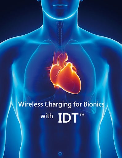
Bionic Organs/Devices/Limbs Wireless Charging
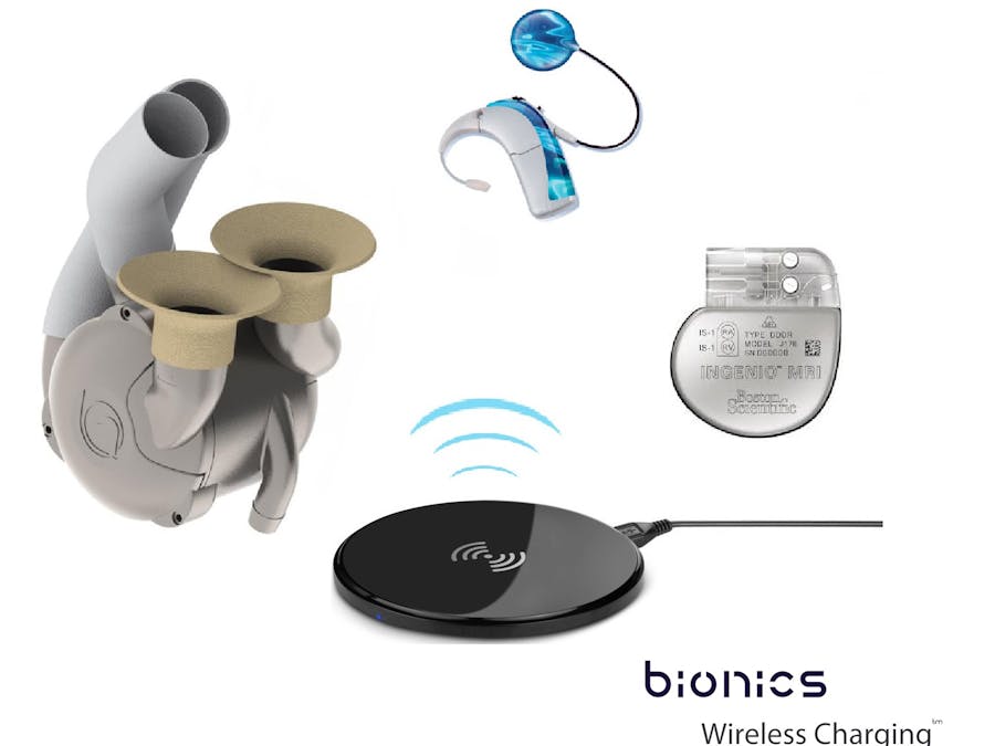
Bionic devices/organs has a limited lifetime where its battery needs to be replaced in order for it to function continually. The limited battery life causes the patient to be subjected to an operation every time the battery life comes to its end. This puts the patient in great danger and discomfort. To solve this problem, wireless charging becomes a very crucial asset. If wireless charging is integrated with bionic organs/devices, the only operation the patient would undergo is to only implant a bionic organ/device. In my opinion, I think that this could be a life saver for humans in the future of electronics to come.
IDT's wireless Transmitter and the Receiver is a huge step forward for Electronics. It is small, compact and programmable. This provides the capability to custom build your own wireless power unit.
The wireless transmitter and receiver can be used in bio medical industry to take a huge leap forward. Using IDT's wireless power platform, bionic devices no longer needs to have batteries that needs to be running for years.
The bionic device can be charged wireless, performance can be monitored, and how much remaining charge it has. Not only IDT's wireless power a great product, but it can also be used as a lifesaver!
In this Project, it is focused on wireless charging of bionic devices inside human beings. Transmitter is controlled by an ATmega328 Micro-controller with an ultrasonic proximity sensor. Proximity sensor is used to activate transmitter only when the Receiver coil is present over the transmitter. This is done to save unnecessary power dissipation in the transmitter coil.
The Transmitter block diagram from Schemeit is shown below:
Transmitter Side Block Diagram
The Receiver Side block diagram from Schemeit is shown below:http://www.digikey.com/schemeit/#2sxs
Receiver Side Block Diagram
Method
Step 1
Program the ATmega328. This can be done using an Arduino Uno R3 board. Inset the ATmega328 into the socket where the ATmega328 in the Arduino Uno R3 board is.
Open the Arduino cc. Use the Transmitter Controller code given below, compile and upload it to the board.
Remove the ATmega328 chip from the Arduino board and inset it to the transmitter board.
Step 2
Connect the controller circuit to the IDT’s P9038-R-EVK wireless Power Transmitter Board as shown below
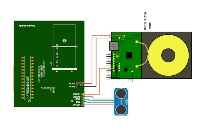
Transmitter circuit connection
Step 3
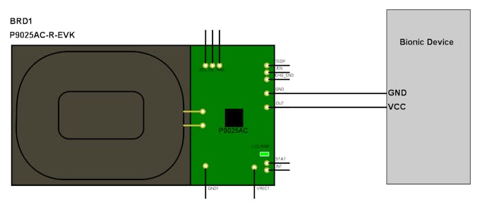
Connect the Bionic Device to the IDT's P9025AC-R-EVK Wireless Power Receiver Board as shown below.
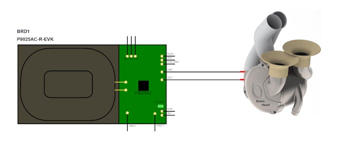
Receiver Circuit connection
The transmitter circuit must be sealed properly in surgical cover to be implanted on the lower back of the body of a person. Charging most suitable will be done when lying down facing upwards.
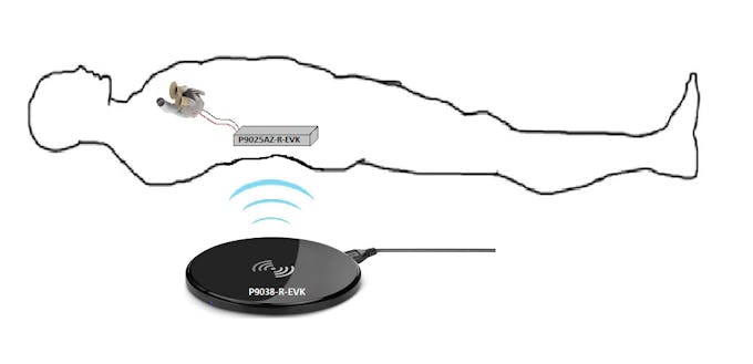
Charging Orientation
The charging system can be customized widely. At the receiver side, the receiver circuit can be programmed to request for a battery status and a working diagnostic from the bionic device. This can pre-identify if there is a problem in the bionic device, or whether the battery is dripping low before the bionic device shuts down. The system can provides extra care for the patient who's life depends on bionics.
Using wireless charging and communication through IDT wireless charging boards will reduce the power consumption that will be used if the bionic device and data is to be collected wireless using modes like WiFi or Bluetooth. This capability will take the bio-medical industry to another level, where devices can be implanted in humans to perform self-Screening.
High-Performance Piezoresistive Electronic Skin with Bionic Hierarchical Microstructure and Microcracks

Electronic skin (E-skin), a popular research topic at present, has achieved significant progress in a variety of sophisticated applications. However, the poor sensitivity and stability severely limit the development of its application. Here, we present a facile, cost-effective, and scalable method for manufacturing E-skin devices with bionic hierarchical microstructure and microcracks. Our devices exhibit high sensitivity (10 kPa–1) and excellent durability (10 000 cycles). The synergistic enhancement mechanism of the hierarchical microstructure and the microcracks on the conductive layers was discovered. Moreover, we carried out a series of studies on the airflow detection and the noncontact speech recognition.
"Bionic" Contact Lens May Create Tiny Personal Displays
A new contact lens embedded with electronic circuits could be the seed for "bionic eyes" that can see displays overlaid on a person's field of view, researchers say.
The minute circuitry could aid the vision-impaired or could be used to create tiny but discernible readouts offering data such as driving directions or on-the-go Web surfing.

Researchers at the University of Washington created the flexible, biologically safe lens—the first of its kind—using nano-scale manufacturing techniques.
The results were presented January 17 at a meeting of the Institute of Electrical and Electronics Engineers in Tucson, Arizona.
"If it works, it would be fabulous," said Blair MacIntyre, who heads the Georgia Institute of Technology's Augmented Environments Lab.
MacIntyre, who was not involved in the new research, works on so-called augmented reality—techniques to overlay visual data using external devices such as headsets.
But a contact lens, he said, could eliminate the need for these bulkier viewing techniques.
Self Assembly
Until recently, display circuitry couldn't be made small and light enough to be placed on a contact lens without a noticeable increase in the lens's weight.
"The nice thing about nanotechnology is that we can make all these parts really tiny," said project leader Babak Parviz, an assistant professor of electrical engineering at the University of Washington.
The first challenge was designing the surface of the lens so the electronics didn't block regular vision.
to place most of the minute components in the areas over the eye's natural blind spots.
Perhaps the more pressing problem was how to attach the electronic components—each thinner than a human hair—to the delicate polymer of a contact lens.
Direct placement would probably damage the lens and be too time consuming.
Instead the team built separate, nano-size metal components and mixed them together so that they appeared like a fine powder.
This powder was then placed in a vial of fluid and poured over a pitted lens surface.
Each pit corresponded to a particular component, so as the mixture washed over the lens, the components found their positions.
A molecular adhesive force known as capillary action—the same property that allows plants to "suck up" water—locked the pieces into place.
The lenses were then put into the eyes of lab rabbits, which showed no signs of adverse effects after at least 20 minutes of wear.
Future Vision
Parviz's team has not yet activated the lens' circuitry; the goal of the new research was to show how such a device could be built and safely worn.
He admits that more research needs to be done in terms of understanding how the human eye would focus on the information.
"It will be difficult to see an image that will be formulated directly on the lens, so we will have to manipulate light so that it appears that the image is further away," he said.
If commercialized, the first generation of lenses would likely have low-resolution displays that probably could not convey much information.
But as the technology improves, the possibilities would be seemingly unlimited, the researchers said.
Drivers could read directions without taking their eyes from the road. Mechanics could get diagrams overlaid onto their equipment as they work. And virtual gamers could use the real world as a backdrop for their adventures.
At Georgia Tech, MacIntyre's lab recently assembled a prototype virtual tour of the historic Oakland Cemetery in Atlanta.
As visitors move about the grounds, they hear voice actors tell the stories of cemetery residents through a special headset and handheld controller.
Replacing such devices with enhanced contact lenses would be easy, MacIntyre said, and the public would readily adopt such lenses if they were useful and unobtrusive.
After all, he noted, people are already becoming acclimatized to a variety of mechanical enhancements.
"I never would have imagined five years ago," he said, "that so many people would be wearing those little Bluetooth headsets."
Definition of bionic : of or relating to bionics: having normal biological capability or performance enhanced by or as if by electronic or electronic mechanical devices
XXX . XXX Six million dollar man : Electronic Devices You Can Control with Your Thoughts

In my Scientific American column this month, I wrote about the dawn of the brain–computer interface. Forget about keyboard, mouse, touch screens or even voice recognition: the real dream is thinking about what you want your gadget to do.
BCI (brain–computer interface) has long been a favorite of sci-fi movies (paging Professor Xavier!). However, some early BCI products are already for sale. Unfortunately, this isn't the dawn of BCI—it's the pre-dawn. These products are crude, imprecise and sometimes frustratingly nonresponsive—that's how it goes with EEG-based headsets, which pick up only the faintest electroencephalographic echoes of neural activity through the skull. (Beware, in particular, of the toys, which garner Amazon reviews ranging from wildly polarizing to absolutely scathing.) But these technologies are based on real BCI principles, and when they work, they're a fascinating glimpse of mind–machine merging mergers to come. (Below are representative online prices, such as those found on Amazon.)
Star Wars Science Force Trainer ($35): This toy includes a wireless headset, ping-pong ball and a clear plastic tube with a fan beneath. As you concentrate, your brain activity turns up the fan so that it blows a ping-pong ball up a tube. Yoda's voice guides you: "Reach out with your feelings! Use The Force. Do or do not; there is no try."
Mindflex ($47): Mattel's game is another ball-in-an-air-column setup. This time the object is to guide the ball through hoops, hurdles, funnels and a seesaw. You control the fan power, and therefore the height of the foam ball, with your thoughts; you control the ball's horizontal movement through the course with a knob.
Mindflex Duel ($44): For about the same price, you can buy a two-headset version of the Mindflex. In some games, your concentration controls the fan strength—as in the original game; in others, it controls the lateral movement of the sliding fan, so that you and a buddy can have a kind of "think of war" battle.
Neural Impulse Actuator ($107): This "brain mouse" is marketed as a Windows game-playing accessory that lets you control game functions with your thoughts. You can assign it to trigger left-clicks, for example, or to make your character walk or shoot.
MindSet ($199): This $199 headset, from NeuroSky, is a traditional Bluetooth headset, suitable for Skype calls and so on. But it's also an EEG headset, a somewhat less frivolous one than the games described above. The software includes a simple "brain-wave monitor" app, but the real potential lies in the developer kit, which allows programmers to come up with their own MindSet-driven software.
EPOC ($299): Emotiv's $299 headset is the most serious consumer option yet. The wired headset has 16 contacts, and you're supposed to wet them with saline solution for better contact. As a result, the sensitivity is far superior to what you get from the dry-connection, single-contact headsets.
XXX . XXX 4 zero Controlling Electronic Devices with Brain Waves
With the growing dependence of mankind on the use of different electronic devices in day to day life, man wants to have easy handling to these electronic devices and easiest one is the possible brain wave command to electronic devices. Users want electronic devices to work through the control of brain waves without even to use of hands. Scientists and engineers are working to make this happen and great advances have been achieved towards brain-computer interface (BCI) or controlling electronic devices with brain waves. Forget about keyboard, mouse, touchscreens or even voice recognition: the real dream is thinking about what we want our electronic gadget to do.
Imagine a future where we can move anything with just our mind. The idea of interfacing minds with machines has long captured the human imagination. The brain is an electrical device and electricity is its common language and this is what allows us to interface the brain to electronic devices. The brain is made up of billions of brain cells called neurons, which use electricity to communicate with each other. The combination of millions of neurons sending signals at once produces an enormous amount of electrical activity in the brain, which can be detected using sensitive medical equipment (such as an EEG), measuring electricity levels over areas of the scalp.
The combination of electrical activity of the brain is commonly called a Brainwave pattern. Our mind regulates its activities by means of electric waves which are registered in the brain, emitting tiny electrochemical impulses of varied frequencies, which can be registered by an electroencephalogram. Recent advances in neuroscience and engineering are making this idea a reality, opening the door to restoring and potentially augmenting human physical and mental capabilities. Medical applications such as cochlear implants for the deaf and deep brain stimulation for Parkinson’s disease are becoming increasingly commonplace. Brain-computer interfaces (BCIs) (also known as brain-machine interfaces or BMIs) are now being explored in applications as diverse as security, lie detection, alertness monitoring, telepresence, gaming, education, art, and human augmentation.
Brain-computer interface
A brain–computer interface (BCI), sometimes called a mind-machine interface (MMI), direct neural interface (DNI), or brain–machine interface (BMI), is a direct communication pathway between an enhanced or wired brain and an external device. Brain-computer interface is collaboration between a brain and an electronic device that enables signals from the brain to direct some external activity, such as control of a cursor or a prosthetic limb. When neurons in the brain interact via chemical reactions, measurable currents called brain waves are created.
The four main types of brainwave patterns are delta, theta, alpha, and beta, and these can be detected and interpreted and signals sent wirelessly to devices to control them. The interface enables a direct communications pathway between the brain and the object to be controlled. BCIs are often directed at researching, mapping, assisting, augmenting, or repairing human cognitive or sensory-motor functions. BCI (brain–computer interface) has long been a favorite of sci-fi movies. However, some early BCI products are already for sale. These products are crude, imprecise and sometimes frustratingly nonresponsive—that’s how it goes with EEG-based headsets, which pick up only the faintest electroencephalographic echoes of neural activity through the skull.
But these technologies are based on real BCI principles, and when they work, they’re a fascinating glimpse of mind–machine merging mergers to come. Consider the potential to manipulate computers or machinery with nothing more than a thought. It isn’t about convenience — for severely disabled people, development of a brain-computer interface (BCI) could be the most important technological breakthrough in decades. It may soon be possible for anyone, everyone, to control technologies using a wearable mind control device based on EEG or electroencephalogram technology.
How it works
The reason a BCI works at all is because of the way our brains function. Our brains are filled with neurons, individual nerve cells connected to one another by dendrites and axons. Every time we think, move, feel or remember something, our neurons are at work. That work is carried out by small electric signals that zip from neuron to neuron as fast as 250 mph. The signals are generated by differences in electric potential carried by ions on the membrane of each neuron. Although the paths the signals take are insulated by something called myelin, some of the electric signal escapes. Scientists can detect those signals, interpret what they mean and use them to direct a device of some kind.
With an EEG or implant in place, the subject would visualize closing his or her right hand. After many trials, the software can learn the signals associated with the thought of hand-closing. Software connected to a robotic hand is programmed to receive the “close hand” signal and interpret it to mean that the robotic hand should close. At that point, when the subject thinks about closing the hand, the signals are sent and the robotic hand closes. Once the basic mechanism of converting thoughts to computerized or robotic action is perfected, the potential uses for the technology are almost limitless. Instead of a robotic hand, disabled users could have robotic braces attached to their own limbs, allowing them to move and directly interact with the environment.
This could even be accomplished without the “robotic” part of the device. Signals could be sent to the appropriate motor control nerves in the hands, bypassing a damaged section of the spinal cord and allowing actual movement of the subject’s own hands. The most common and oldest way to use a BCI is a cochlear implant. For the average person, sound waves enter the ear and pass through several tiny organs that eventually pass the vibrations on to the auditor nerves in the form of electric signals. If the mechanism of the ear is severely damaged, that person will be unable to hear anything. However, the auditory nerves may be functioning perfectly well.
They just aren’t receiving any signals. A cochlear implant bypasses the nonfunctioning part of the ear, processes the sound waves into electric signals and passes them via electrodes right to the auditory nerves. The processing of visual information by the brain is much more complex than that of audio information, so artificial eye development isn’t as advanced. Still, the principle is the same. Electrodes are implanted in or near the visual cortex, the area of the brain that processes visual information from the retinas. A pair of glasses holding small cameras is connected to a computer and, in turn, to the implants. After a training period similar to the one used for remote thought-controlled movement, the subject can see.
Advantages
Every technology is said to have its pros and cons and same will be the case with brain wave interface with electronic devices. However, the interest of users is the most important parameter to influence the development and market growth of any technology. The recent history of human technology shows an increasing number of products and services that can be controlled remotely and automatically using computer algorithms. But what are the prospects of controlling devices using our brain waves.
A few paralyzed patients could soon be using a wireless brain-computer interface able to stream their thought commands as quickly as a home Internet connection. By reading signals from an array of neurons and using computer chips and programs to translate the signals into action, BCI can enable a person suffering from paralysis to write a book or control a motorized wheelchair or prosthetic limb through thought alone. Current brain-interface devices require deliberate conscious thought but future applications, such as prosthetic control, are likely to work effortlessly.
Challenges
One of the biggest challenges in developing BCI technology has been the development of electrode devices and/or surgical methods that are minimally invasive. In the traditional BCI model, the brain accepts an implanted mechanical device and controls the device as a natural part of its representation of the body. Much current research is focused on the potential on non-invasive BCI. One of the biggest challenges facing brain-computer interface researchers today is the basic mechanics of the interface itself. The easiest and least invasive method is a set of electrodes — a device known as an electroencephalograph (EEG) — attached to the scalp. The electrodes can read brain signals. However, the skull blocks a lot of the electrical signal, and it distorts what does get through.
To get a higher-resolution signal, scientists can implant electrodes directly into the gray matter of the brain itself, or on the surface of the brain, beneath the skull. This allows for much more direct reception of electric signals and allows electrode placement in the specific area of the brain where the appropriate signals are generated. This approach has many problems, however. It requires invasive surgery to implant the electrodes, and devices left in the brain long-term tend to cause the formation of scar tissue in the gray matter. Although we already understand the basic principles behind BCIs, they don’t work perfectly and there are several reasons for this as:
- The brain is incredibly complex. To say that all thoughts or actions are the result of simple electric signals in the brain is a gross understatement. There are about 100 billion neurons in a human brain. Each neuron is constantly sending and receiving signals through a complex web of connections. There are chemical processes involved as well, which EEGs can’t pick up on.
- The signal is weak and prone to interference. EEGs measure tiny voltage potentials. Something as simple as the blinking eyelids of the subject can generate much stronger signals. Refinements in EEGs and implants will probably overcome this problem to some extent in the future, but for now, reading brain signals is like listening to a bad phone There’s lots of static.
- The equipment is less than portable. It’s far better than it used to be — early systems were hardwired to massive mainframe computers. But some BCIs still require a wired connection to the equipment, and those that are wireless require the subject to carry a computer.
Developments
- Video games have started to use EEG technology, equipping gamers with sleek headsets that claim to read the gamer’s mind and translate their thoughts into machine-readable instructions. Gamers can use their minds to drive a virtual car and create musically-inspired brain-wave art. A firm has developed what it considers to be the next level in gaming – a headset that lets us to control on-screen and physical objects using just our mind. During the demonstration, the brain waves moved a car the size of a shoebox around a track and each race involves two players wired up to the headset.
- Neural prosthetic devices also use the shared language of electronics to control robotic limbs, but through a somewhat more sophisticated interface with the brain. These devices use neural implants consisting of an array of electrodes that are implanted in the brain to monitor a small set of neurons and detect an individual’s intentions to maneuver an object such as a prosthetic limb. Mathematical formulas then decode these brain signals and turn them into instructions that drive the prosthetic device.
- Today it’s a headband or a helmet that reads brain waves from external EEG sensors, but to get to the subtleties that a true user interface would require we’d need to put sensors inside the head or add more components, such as the vision mentioned in the research above. But if we want to rely on the brain, then we need better electronics that could be implanted into a person’s body, which requires new coatings and research into chips.
- The “mind control” headband unveiled by startup BrainCo. effectively hacks into brain signals with a range of possible applications — from helping to improve attention spans, to detecting disease, controlling smart home appliances or even a prosthetic device.
- The helmet is built around a NeuroSky headset, an EEG device that senses the activity of neurons in the brain and indicates whether a person’s thoughts are either meditative or attentive.
- The US Department of Defense is pushing for the development of cheap, wearable systems that can detect the brain waves of people and display the data on smartphones or tablets.
XXX . XXX 4 zero null Technological Miracles with Electronics
People at work, home or around demand technology that can keep up with their fast-paced lives. Appliances and electronics must work faster, better and more reliably than ever before- and get more accomplished in less time. Electronic devices are not only leading the day to day life activities but have given some miraculous technologies in various fields like medical, sensing and security, business, lighting, entertainment, sports, communication, transportation, space exploration, weather and natural disaster prediction and many more technological avenues with tremendous development towards the benefit of mankind which can simply be termed as technological miracles through electronics.
Electronics will certainly play a large part in the new world and solve many industrial problems. Electronics will create jobs in many other fields, and perhaps by reducing manufacturing costs of many items. The present article is a small effort in this direction to briefly highlight some of such technological miracles through electronics.
The junction of electronic design and medical science is truly a place where miracles can occur. Today’s medical technology relies increasingly on electronics hardware at just about every level. Medical devices that electrically stimulate tissues are not new, but they have emerged into the medical mainstream in recent decades. Technological miracles help us live longer, healthier, data driven lives. Cochlear implants help the hard of hearing by stimulating neurons in the brain’s auditory cortex, while deep brain stimulation improves mobility for those with Parkinson’s disease by delivering electrical pulses that inhibit abnormal nerve signals. Peoplewith paraplegia can control their bladder through sacral nerve stimulation, facilitating communication between the bladder and brain.
 These devices are medically revolutionary, and they represent just a small sample of what is possible for bioelectronic medicine. Though, electrical treatments are unlikely to replace drugs, instead, they will joining forces. For decades, drug pumps have been a “set it and forget it” type of treatment, delivering the same amount of drugs regardless of the patient’s condition but a device that combines electrical treatments and drug pumps could target an area of the body, use sensors to read the patient’s physiology and condition, and deliver the correct dose of drugs to just the right tissue.
A novel combination treatment, part pharmaceutical and part bio electronics: pills that dissolve into particles in the body, while an external power source, similar to today’s ultrasound machines, would use magnetic fields to remotely direct the particles to different nerves. This futuristic medicine, currently in development, would eliminate the need for surgical implants. It would be the ultimate smart pill that could one day help treat many diseases. Further, a temporary bio electronic device implanted on the lower spinal cord will transmit electrical impulses, mimicking brain signals, from below the spinal injury to the legs resulting in mobility.
The world’s first sterilizable, flexible organic transistor; mobile apps that can measure pulse just by imaging face; X-ray machines that capture not just bone but cancer tissue, too are just a few of the technologies being developed. Medical Nanobots are part of an emerging technology that hopes to use microscopic robots to travel inside the human body to collect information and make minor repairs. Here are few special electronics based medical miracles which we are encountering in the medical field on our every day routine.
 Patient’s health: Welcome to the technology revolution in health care, the electronics based technology is rolling out a host of products that let us track, monitor and report on our health and wellness-alerting us to warning signs of more serious problems long before our next annual physical. When we go to see a doctor, the first thing we see is an electronic sign board asking to turn off the cell phone. Next, we get weighed on a digital scale, and temperature and blood pressure are taken digitally.
As the nurse works up our profile on a specialized laptop computer with a touch screen, we may wonder just how much of our life is contained in that hard disk drive. Then the doctor comes in, and he has a similar laptop computer, making touch-screen entries as he interviews us. Then finally we can tap the screen to place an order for prescription medicines with our favorite drug store. For a follow-up appointment in a scheduled time, we request the receptionist and she uses a computer to schedule it. Sitting in a visitor’s chair, one can watch the whole process of medical treatment of the patient on screen by a computer and various diagnostic tools to measure vital signs – all performed very quickly, and all electronically.
What’s even more amazing is that while sitting in hospital one can work at his job on a notebook computer. One of the most important aspects of today’s medical culture is the pedigree of the electronics that are used. Life-saving and tactical products have to be ultra-reliable and must have verifiable pedigrees, a paper trail (usually paperless these days) that certifies each component and manufacturing process. Today we are especially grateful for all of this wondrous technology, and the medical miracles that it helps to perform on a daily basis.
Medical bluetooth: Pervasive broadband in the industrialized world and the new cellular infrastructure in developing countries mean that health care can “reach out and touch” patients like never before. Though, insurance companies are still working out the details on how they’ll compensate for virtual doctor visits, but remote medicine should bring more flexible care and better efficiency to the healthcare system. Bluetooth offers an easy path for medical device connectivity. With portable medical devices connecting to the cell phone, it will be easy for patients to check in with their doctors to report their vital signs from anywhere they roam.
Remote communications also can bring advanced medical care to undeveloped areas. By offering remote heart-care diagnostics, doctors can analyze data and then decide if a patient needs to travel to a clinic for further care. It’s a noble vision with an aim to include processors inside the phones to forecast. Ultrasound and medical imaging get higher resolution and better clarity, faster scans, and more portable form factors. Similarly, portable devices like the automated external defibrillator take advantage of processors initially developed for cell phones, providing LCD graphics that allow an easy interface for inexperienced users.
Medical implants: Bioelectronic devices surgically implanted on nerves interfere with and change the body’s own processes to make them function better. In the present world of electronic medical implants, human lifespan has been increased, we are living stronger and healthier plus we generally feel better. Think of pacemakers, pacemakers with defibrillators, implanted insulin pumps, spinal stimulators and brain-machine-interface (BMI) devices just to name a few of these marvels of electronic innovation that have helped correct ailments in our relatively fragile bodies.
There are challenges to implanting electronic devices in the body. The devices must use little power — whether they scavenge it from the body, include an internal battery, or use an inductive power transfer technique. The devices must be packaged in a way that the body won’t reject the foreign matter, as it is wont to do. There must be a bidirectional way to pass information. The devices must be extremely reliable, and they usually require very high amounts of integrated functionality. Tiny electronic sensors and devices that can be implanted in the body and then dissolve almost without a trace are getting closer to reality. Scientists have tested several biodegradable materials, including DNA, proteins and metals, for making transient electronics.
Electronic wearable’s: Consumers say these devices help them achieve fitness goals, increase awareness of their personal health and empower them with useful data about their activity levels. wearables are becoming more and more sophisticated-shifting from “nice-to-have” trackers to life changing devices. Development of a sensor can detect concussions in the military personnel. A device can detect subtle temperature changes that occur before ovulation, then inform women when they are most likely to conceive. A smartphone-compatible urinalysis strip can instantly measure a dozen different physiological levels, including glucose, protein and bilirubin levels.
As wearables evolve and the concept of “the quantified self” takes root, the chairs we sit in, the beds we sleep in and the cars we ride in may soon alert us to early indicators of changes in our health. Wearable electronic fingertip and fingertips pave will make surgeons able to repair from their fingertips. Electronic materials have been a major stumbling block for the advance of flexible electronics because existing materials do not function well after breaking and healing. A new electronic material created by an international team, however, can heal all its functions automatically even after breaking multiple times. This material could improve the durability of wearable electronics.
 Bionic miracles: Great strides of technology in areas of bionics have really improved our way of living if it is put to proper use of human beings. Bionics is the application of biological methods and systems found in nature to the study and design of engineering systems and modern technology to make it useful to human beings in need. Bionics is an interscience field of science and engineering of constructing artificial systems that have some of the characteristics of living systems. The science of designing, constructing, evaluating, and maintaining artificial systems that imitate living systems is called bionics. Bionics make use of models of living systems, in order to find new ideas for useful artificial machines and body systems to make technological engineering systems useful for human beings those who need them.
Brain stimulation: Electric dominance of brain working is well confirmed and established by health and neural sciences. Electric signals with in the brain not only govern/control the working of human body but according to recent medical studies these signals with suitable electric brain simulation techniques can be controlled to enhance the desired activities of human body like, motion, memory, health, peace, and many more.
Others:
- A wearable device promises to help steady hand tremors by using an old technology-gyroscopes.
- Futuristic hospital bracelet tracks our vitals.
- With the use of clever placement of the watch-face we can quickly glance down discreetly during work meetings or among company without appearing rude.
Future scope: Medical electronics products have the quality and reliability to be used in applications critical to the diagnosis of patients throughout the world. Such products are being used in various forms as medical analyzers, blood pressure testers, blood sugar monitors, heart monitors, biopotential analyzers, pacemaker analyzers, ECG transmitter/receiver units, to name a few. The prognosis for medical electronics is very strong. The worldwide market is more than $70 billion, with double-digit growth forecast for diagnostics and therapy, home medical, and imaging technologies.
Applications are moving out of the hospital and into the patients’ world via portable, wearable, and implantable devices. Reliability and low power are two obvious requirements in the mobilized medical market. Under development is an implantable microchip that will release scores of different drug combinations over a period of weeks or even months. Drug release can be triggered by a wireless electronic signal or through a programmed biological system.
Industry
The variety of functions of which electronics is capable, in industrial applications alone, could not be described in anything short of an encyclopedia. All we can do here is to glance at a few things electronics can do better than they were done before, and others which, without electronics, could not be done at all. The great impact will come, not through any one spectacular development, but through the expanding uses of electronics in industry. Some of the key industrial technological developments based on electronics can be summarized as:
- The production of countless necessities of life as, houses, autos, machinery, tools, are being immeasurably speeded up and improved with the use of electronics based applications.
- Factory production is being made more and more automatic by amazingly accurate electronic methods of sensing and measurement & control.
- With the progress in the use and features provided by the smart phones, life is going to be affected by electronics in many ways in the times to come.
- We now know how to control manufacturing operations with superhuman accuracy, how to assemble materials with amazingly precise methods of welding, and how to run motors at infinitely varying speeds to suit each changing phase of machine operation and that too automatically.
- Electronic measurements may deal with quantities inappreciable except by almost incredibly sensitive instruments or as great as the distance of a star from the earth. They may soar out into space or burrow into the earth.
- In scientific exploration for oil, dynamite is exploded in a shot hole, setting up a small artificial earthquake. Suitably disposed pickups, designed to convert earth vibrations into electrical vibrations, respond to the reflections from the underlying rock strata. The outputs of the pickups are amplified electronically and recorded as seismograph traces, which permit mapping substrata as deep as 20,000 feet.
- Nowadays, machine parts are commonly made with a tolerance of less than a ten-thousandth of an inch. Length, thickness, speed, time, mass, illumination, chemical composition, electrical quantities are all measured with an accuracy of only a few parts in a million, and usually we find electronic or semi-electronic devices doing the measuring. An example of a wholly electronic measuring instrument is the cathode-ray oscillograph, called “the most versatile measuring instrument ever devised by science. The operating principle of the cathode-ray tube is the deflection of an electron beam by electrodes in the neck of the tube, to which an unknown variable voltage is applied. Functioning as a weightless pointer, the beam traces a curve on a fluorescent screen, which shows how the voltage varies with time. The magnitude and duration of welding currents, the behavior of electronic motor controls, and of every other electronic or electrical machine, can be studied in the utmost detail. By using some form of pickup to convert mechanical into electrical energy, the vibrations of machines, engines, musical instruments, and timepieces may be analyzed. Metals may be tested for composition and characteristics by observing their magnetic or electrical behavior when subjected to high-frequency fields.
- The usual method of measuring the speed of a rotating machine was to stick a mechanical tachometer or revolution counter against the end of the shaft. In the case of a very small motor, the tachometer load might be enough to slow it down. With high-speed machines, the method was likely to be inaccurate because of slippage. By means of an electronic stroboscope using a light flashing at a known frequency, the speed of a rotating object may be measured accurately without contact.
- The new technique of resistance welding requires electronic control. The process consists in joining metal parts by pressing them together mechanically, sending an electric current through the joint, and then shutting off the current and maintaining the pressure for another instant while the molten metal “freezes.” Any deviation may mean the difference between a perfect weld and a poor one. Some types of precision resistance welding are actually done in a fraction of a cycle, and it has to be the same fraction each time, in the same part of the cycle. Making and breaking currents of this magnitude is a ticklish job, and it has to be done automatically hundreds of times a minute. About the only kind of switch that measures up to the job is a frictionless and inertia less device in which small amounts of power can control large amounts in short, an electronic device.
- Induction heating, a comparatively new method of applying heat in industrial operations, has also contributed materially to manufacturing, and promises to play a significant part in electronics. With electronic methods, heat may be produced within the material, so that, if desired the whole mass can be kept at a uniform temperature throughout the process or with equal ease, electronic heat may be applied selectively.
- In the development of mercury-arc and other electronic rectifiers for large-scale conversion of AC into DC, we see one of those long-term swings in technological history that color the lives of millions. The availability of convenient and efficient rectifiers, in turn, encourages industrialists to use DC equipment for many other purposes. So DC and electronics, in partnership, are going places. Even in the field of long-distance power transmission, in which AC has reigned unchallenged for half a century, it may have to move over and make room for DC.
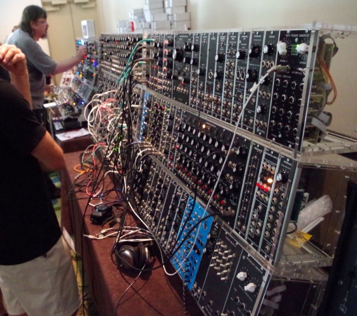
- Music technology has changed to new heights with the application of electronics based instruments like, sequencers and synthesizers, Musical Instrument Digital Interface (MIDI) controllers, Electronic Music & Recording Gear, and lots of inexpensive electronic music apps.
- There is a multitude of electronic detecting, counting, sorting, and inspecting devices. The inertia of electrons is negligible, and photoelectric relays are now made to operate reliably 1,000 times a minute. Some electronic counting systems will respond to half a million counts a minute. From counting it is only a step to sorting.
- Electronic devices can be used not only to replace the human senses and muscles, but to veto human actions.
- Innovative and more stretchable materials with dramatic advancements help in making electronic ink to give interface designers new creative freedom, without any compromise in meeting functional switching needs. And because these new electronic inks work with existing decorative processes, there’s no need for costly re-tooling and products with greater eye appeal, simplicity, and performance-all at the same time can be created.
- With a deep understanding of materials science and technology, a wide range of process expertise in high performance electronic materials can be useful for hybrid, rigid and flexible circuits; specialized ceramic, polymer thick film compositions and low temperature co-fired ceramic materials; materials for the fabrication and packaging of semiconductors; and materials for advanced displays.
- Electronics based sensors have increased the control over many un-wanted outcomes not in industrial processes but also in quality of items for day-to-day uses. A sensor is a device that detects and responds to some type of input from the physical environment. The specific input could be light, heat, motion, moisture, pressure, or any one of a great number of other environmental phenomena. The output is generally a signal that is converted to human-readable display at the sensor location or transmitted electronically over a network for reading or further processing. Electronic sensors are used in everyday objects such as touch-sensitive elevator buttons and lamps which dim or brighten by touching the base, besides innumerable applications of which most people are never aware. With advances inmicro-machinery and easy-to-use micro controller platforms, the uses of sensors have expanded beyond the most traditional fields of temperature, pressure or flow measurement and analog sensors such as potentiometers and force-sensing resistors are widely used. Applications include manufacturing and machinery, airplanes and aerospace, cars, medicine, and robotics.
- Transportation sector has already seen various types of advances in terms of electric vehicles, un-manned planes (drones), use of global positioning system (GPS), high speed vehicles, electronics based safety measures in vehicles etc.
- Electronics based surveillance and security has made tremendous strides for the benefit of mankind.
- Valleytronics would be a movement away from exploiting the electrical charge of electrons as a means for storing information, and instead using the wave quantum number of an electron in a crystalline material to encode data. The aim of valleytronics is to find a faster way of encoding information than moving electrical charges around at high switching rates, which is the basis of electronics.
- Space electronics has been a major driving force for the development of electronics and is subject to very harsh environmental conditions. First of all, the electronics must survive the vibrations imposed when the rocket is launched. Secondly, it has to be able to withstand very high temperature variations. Due to the vacuum in space, there is no thermal convection or conduction taking place, with the only heat transfer mechanism remaining being radiation.Even with all these environmental limitations space electronics has proved to be miraculous technology in the space vehicles, satellites and space stations.
- Electronic sports or e-sports, is a form of sports where the primary aspects of the sport are facilitated by electronic systems; the input of players and teams as well as the output of the eSports system are mediated by human-computer interfaces.
- Electronics based technologies are able to help us understand more about how the human body copes with various training methodologies towards sports. In fact, in order to improve the quality of training prescriptions we need to base them on data and be able to provide an evidence-based approach to athletic training. We have now access to sophisticated tools capable of measuring a lot of aspects of human performance. This will allow the system to simultaneously capture positioning and movement data in conjunction with vital parameters such as pulse and respiratory rate. This information is subsequently used to create an optimized training concept.
- The automotive and transportation industries present a set of challenges for electronics including being able to withstand high levels of motion and heat, and long lifetime requirements along with the industries drive to zero defect electronic assemblies as a product of their requirement for high reliability. With radical changes in electronics based technology, a number of sophisticated devices are making their way into our vehicles. These include advanced in-dash infotainment systems, multi-function displays for instrument clusters, electronics-based vehicle control and guidance systems and telematics for a number of never-before capabilities related to safety, vehicle diagnostics, maintenance and insurance.
- As always designers and engineers are looking for more complex and high tech products. The industry can now print complex objects in a variety of materials. Although 3D-selfies are grabbing the media headlines at the moment, designers and engineers are already building far more complex, high-tech products. The secret is to combine electronics (such as sensors/switches) as the object is being printed. Costs are much lower when the product is made in a single process, without the need for individual circuit-board assembly.
XXX . XXX 4 zero null 0
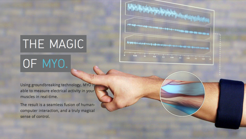
Controlling Electronic Devices With Your Arms (Yes… Your Arm!)
Google Glass is a very interesting project and although it has a lot of uses it would certainly be weird to change your song on your iPod in public by saying, “Next Song”. Well maybe it’s just me because realistically there are thousands of people looking odd at first using a Bluetooth headset, Siri or some other voice detection system. Now this is something new and surprisingly has a lot of practical functions. It’s called MYO by Thalmic Labs and it’s a wearable armband that allows you to send signals using the electrical pulses sent by your muscles during movement. The product will be shipping in late 2013 for $149 with an open API for developers to build or connect it to their own programs and applications.

The process is called electromyography and it measures the activity from your forearm contracting and producing small amounts of electrical activity. The device then amplifies that activity by thousands of times and processes the signals. The great thing is that it will get more and more accurate over time as the device learns your specific movements more precisely and thus it’s algorithms and accuracy improves. This technology is similarly found in high tech arm and hand prosthetics.
When a recognized command is completed you can have a small vibration occur to confirm an operation such as pointing/pinching a finger or waving/swiping your hand. The Myo’s sensors can determine when a certain gesture is being made and translate it into a digital command for your computer, phone or remote controlled vehicle.
Given it might not be the new hot item that everyone NEEDS you have since it isn’t made by Apple or isn’t prefixed with an i such as iMyo, it’s still a neat item that could have many uses in the home, business, teaching, health and recreation environments. Things are definitely changing and consumers are starting to witness emerging technologies that they never would have thought of embracing years prior. “Right now we’re just on the cusp of a major shift in computing, and whether it’s a Google product or something else, at some point in the next couple years wearable computing devices are going to change how everyone will communicate and interact with technology,” says Thalmic Labs co-founder Stephen Lake. “Ultimately the line between us and our devices will start becoming a lot more blurred.”
In a video showcasing some of the Myo’s uses you can view it controlling video and audio playback, switching between windows on a computer, shooting a gun in a game, directing remote controlled devices and even sending a video to share on social networks WHILE you’re skiing! The device isn’t just limited to a few uses though. “If you think about your daily life, you use your hands to interact with and manipulate just about everything you do, from pressing numbers on your phone to picking up your coffee,” says Lake. “Now think if we can take all those motions and actions and plug them into just about any computer or digital system, the possibilities are endless.”
In truth we’ve always wanted to have some kind of advanced computer on our wrists to make us feel like super heroes or futuristic badasses How amazing would it be to play a Star Wars game and force choke someone with your own hands!? I wouldn’t be surprised if in 5 or 10 years everyone has some sort of hybrid device strapped to their body (besides the current cell phone of course!). I’m thinking more of a wrist watch that has holographic type capabilities and it will be our phone, computer, projector and maybe even stereo. As cool as it would be I hope it doesn’t turn into some thing that every “citizen” is required to have because it identifies and GPS tracks you.
Remotely controlling electronic devices with hand gestures

Moving things with a wave of the hand: thanks to Empa technology this dream could soon become real. A sensor made of piezo-resistive fibers integrated in a wristband measures wrist movements and converts them into electrical signals. This can be used to steer drones or other electronic devices without a remote control.
A wave to the left: the drone moves to the left. A wave to the right: the drone turns right. Clench your hand into a fist and it lands gently on the table. No, not crazy talk; reality. Empa researchers headed by Frank Clemens from the Laboratory for High-Performance Ceramics have devised a sensor made of piezo-resistive fibers and incorporated it into a wristband that registers the hand's movements. The piezo-resistive fiber is electroconductive, recognizes a change in shape and converts it into an electrical signal, which can then be read by a terminal device and interpreted accordingly. This means that robots can be moved with a simple point of the finger, for instance.
Although motion sensors are nothing new, until now movements were primarily recorded using visual sensors (such as cameras), accelerometers and gyroscopes (for rotational movements). This manner of registering movements, however, requires large, clear movements within a particular speed range that are, by and large, unnatural for humans. The new Empa sensor, on the other hand, responds to the minutest of natural movements made "off the cuff". Nonetheless, Clemens doesn't want to do away with previous technologies. "It takes a combination of different sensors to develop new concepts. Only then can we spot and use movements that weren't detectable with previous technologies." Combining acceleration, rotation and orientation sensors with the new fiber sensor would facilitate completely new "commands" to control technical devices – whether it be a drone or the garage door.
Algorithms "translate" movements
For test purposes, the researchers integrated the sensor in a conventional wristwatch strap, which can be worn unobtrusively and restricts the wearer as little as possible. Run-of-the-mill decorative bracelets are also conceivable. Nevertheless, it took quite a while to reach this stage. In the first prototypes, Frank Clemens and Mark Melnykowycz succeeded in attaching the piezo-resistive fibers to a piece of fabric. This was insufficient to use the sensor on the desired scale, however. "With the aid of additive manufacturing, we managed to integrate the sensor structure in non-textile materials," explains Clemens. The sensor could thus eventually be used in existing wristwatch straps.
Wearing the sensor in a wristband might soon be a thing of the past, too. In the possibility of integrating the piezo-resistive sensor in a plaster. Then all that would be needed to perform diverse interactions with technical devices and robots would be a barely conspicuous plaster on the wrist. Although the project is still very much in its infancy, everything already works perfectly.
Touch-sensitive fibers put new twist on controlling electronic devices

Polymer tubes filled with liquid metal are twisted together to form a conductive fiber(Credit:North Carolina State University)
We're used to touchscreens, but now researchers have created new, touch-sensitive fibers that can be used to interact with electronic devices. The microscopic fibers are soft, stretchable and capable of detecting touch, strain and twisting, all of which could lead to new sorts of wearable devices and sensing applications.
The fibers created at North Carolina State University are made of a extremely thin strands of a tube-like polymer filled with a liquid metal alloy of eutectic gallium and indium (EGaIn). The strands are a few hundred microns in diameter, or just a little thicker than a human hair.
To create the fiber shown in the video below, three strands are twisted together to form a tight spiral. Each of the tubes are filled to different degrees with the liquid metal alloy – one is completely filled, one is two-thirds full and one is just one-third of the way filled.
The fiber responds to touch in the same way that many phone's screens do by interpreting variations in capacitance between your finger and the electronic components of your phone. This works because both sides of this interaction are conductors of electricity and they're separated by an insulator. In the case of your phone the insulator is the screen. In the case of the fibers, your finger and the liquid metal alloy are conductors and the polymer tubes are insulators.
Just as touching a different part of your touchscreen can be translated into different actions on your mobile device, touching a different section of the fiber can also produce different electronic signals, based on how many strands contain the metal alloy in a particular section of the fiber. Here's a demonstration:
We've seen some similar approaches to creating flexible, wearable electronics using silver nanowires and conductive ink, but the use of liquid metal in this case is particularly interesting.
A two-strand version of the fiber can also be twisted together to measure rotation.
"We can tell how many times the fiber has been twisted based on the change in capacitance," explains Michael Dickey, a professor of chemical and biomolecular engineering at NC State. "That's valuable for use in torsion sensors, which measure how many times, and how quickly, something revolves. The advantage of our sensor is that it is built from elastic materials and can therefore be twisted 100 times more – two orders of magnitude – than existing torsion sensors."
XXX . XXX 4 zero null 0 1 2 3 Remote control
In electronics, a remote control is a component of an electronic device used to operate the device wirelessly from a distance. For example, in consumer electronics, a remote control can be used to operate devices such as a television set, DVD player, or other home appliance, from a short distance. A remote control is primarily a convenience feature for the user, and can allow operation of devices that are out of convenient reach for direct operation of controls. In some cases, remote controls allow a person to operate a device that they otherwise would not be able to reach, as when a garage door opener is triggered from outside or when a Digital Light Processing projector that is mounted on a high ceiling is controlled by a person from the floor level.
Early television remote controls (1956-1977) used ultrasonic tones. Present-day remote controls are commonly consumer infrared devices which send digitally-coded pulses of infrared radiation to control functions such as power, volume, channels, playback, track change, heat, fan speed, or other features varying from device to device. Remote controls for these devices are usually small wireless handheld objects with an array of buttons for adjusting various settings such as television channel, track number, and volume. For many devices, the remote control contains all the function controls while the controlled device itself has only a handful of essential primary controls. The remote control code, and thus the required remote control device, is usually specific to a product line, but there are universal remotes, which emulate the remote control made for most major brand devices.
Remote control has continually evolved and advanced in the 2000s to include Bluetooth connectivity, motion sensor-enabled capabilities and voice control

 An air conditioning unit remote control
In 1894, the first example of wirelessly controlling at a distance was during a demonstration by the British physicist Oliver Lodge, in which he made use of a Branly's coherer to make a mirror galvanometer move a beam of light when an electromagnetic wave was artificially generated. This was further refined by radio innovators Guglielmo Marconi and William Preece, at a demonstration that took place on December 12, 1896, at Toynbee Hall in London, in which they made a bell ring by pushing a button in a box that was not connected by any wires.[3] In 1898 Nikola Tesla filed his patent, U.S. Patent 613,809, named Method of an Apparatus for Controlling Mechanism of Moving Vehicle or Vehicles, which he publicly demonstrated by radio-controlling a boat during an electrical exhibition at Madison Square Garden. Tesla called his boat a "teleautomaton".[4]
In 1903, Leonardo Torres Quevedo presented the Telekino at the Paris Academy of Science, accompanied by a brief, and making an experimental demonstration. In the same time he obtained a patent in France, Spain, Great Britain, and the United States. The Telekino consisted of a robot that executed commands transmitted by electromagnetic waves. With the Telekino, Torres-Quevedo laid down modern wireless remote-control operation principles[5] and was a pioneer in the field of remote control. In 1906, in the presence of the king and before a great crowd, Torres successfully demonstrated the invention in the port of Bilbao, guiding a boat from the shore. Later, he would try to apply the Telekino to projectiles and torpedoes, but had to abandon the project for lack of financing. The first remote-controlled model aeroplane flew in 1932, and the use of remote control technology for military purposes was worked intensively during the Second World War, one result of this being the German Wasserfall missile.
By the late 1930s, several radio manufacturers offered remote controls for some of their higher-end models.[6] Most of these were connected to the set being controlled by wires, but the Philco Mystery Control (1939) was a battery-operated low-frequency radio transmitter,[7] thus making it the first wireless remote control for a consumer electronics device. Using pulse-count modulation, this also was the first digital wireless remote control.
Television remote controls

The first remote intended to control a television was developed by Zenith Radio Corporation in 1950. The remote, called "Lazy Bones", was connected to the television by a wire. A wireless remote control, the "Flashmatic", was developed in 1955 by Eugene Polley. It worked by shining a beam of light onto a photoelectric cell, but the cell did not distinguish between light from the remote and light from other sources. The Flashmatic also had to be pointed very precisely at the receiver in order to work.[8]


In 1956, Robert Adler developed "Zenith Space Command", a wireless remote.[9] It was mechanical and used ultrasound to change the channel and volume. When the user pushed a button on the remote control, it clicked and struck a bar, hence the term "clicker". Each bar emitted a different frequency and circuits in the television detected this sound. The invention of the transistor made possible cheaper electronic remotes that contained a piezoelectric crystal that was fed by an oscillating electric current at a frequency near or above the upper threshold of human hearing, though still audible to dogs. The receiver contained a microphone attached to a circuit that was tuned to the same frequency. Some problems with this method were that the receiver could be triggered accidentally by naturally occurring noises, and some people could hear the piercing ultrasonic signals.
The impetus for a more complex type of television remote control came in 1973, with the development of the Ceefax teletext service by the BBC. Most commercial remote controls at that time had a limited number of functions, sometimes as few as three: next channel, previous channel, and volume/off. This type of control did not meet the needs of teletext sets, where pages were identified with three-digit numbers. A remote control to select teletext pages would need buttons for each numeral from zero to nine, as well as other control functions, such as switching from text to picture, and the normal television controls of volume, channel, brightness, colour intensity, etc. Early teletext sets used wired remote controls to select pages, but the continuous use of the remote control required for teletext quickly indicated the need for a wireless device. So BBC engineers began talks with one or two television manufacturers, which led to early prototypes in around 1977–1978 that could control many more functions. ITT was one of the companies and later gave its name to the ITT protocol of infrared communication.[10]
In 1980, a Canadian company, Viewstar, Inc., was formed by engineer Paul Hrivnak and started producing a cable TV converter with an infrared remote control. The product was sold through Philips for approximately $190 CAD. At the time the most popular remote control was the Starcom of Jerrold (a division of General Instruments) which used 40-kHz sound to change channels. The Viewstar converter was an immediate success, the millionth converter being sold on March 21, 1985, with 1.6 million sold by 1989.[11]
Other remote controls
The Blab-off was a wired remote control created in 1952 that turned a TV's sound on or off so that viewers could avoid hearing commercials.[12] In the 1980s Steve Wozniak of Apple started a company named CL 9. The purpose of this company was to create a remote control that could operate multiple electronic devices. The CORE unit (Controller Of Remote Equipment) was introduced in the fall of 1987. The advantage to this remote controller was that it could "learn" remote signals from different devices. It had the ability to perform specific or multiple functions at various times with its built-in clock. It was the first remote control that could be linked to a computer and loaded with updated software code as needed. The CORE unit never made a huge impact on the market. It was much too cumbersome for the average user to program, but it received rave reviews from those who could.[citation needed] These obstacles eventually led to the demise of CL 9, but two of its employees continued the business under the name Celadon. This was one of the first computer-controlled learning remote controls on the market.[13]
In 2006, Hillcrest Labs introduced the Loop pointer, a remote control that used Hillcrest's Freespace motion control technology to allow users to control their televisions with natural gestures. The Loop had just four buttons and a scroll wheel. Freespace-enabled remote controls use radio waves to communicate with a USB antenna connected to a computer that is also connected to the television, so they do not need to be pointed at the PC, or even have a direct line of sight.[18][19][20]
In the 2010s, cars are increasingly sold with electronic remote control door locks. These remotes transmit a signal to the car which locks or unlocks the door locks or unlocks the trunk. An aftermarket device sold in some countries is the remote starter. This enables a car owner to remotely start their car. This feature is most associated with countries with winter climates, where users may wish to run the car for several minutes before they intend to use it, so that the car heater and defrost systems can remove ice and snow from the windows.
Proliferation

By the early 2000s, the number of consumer electronic devices in most homes greatly increased, along with the number of remotes to control those devices. According to the Consumer Electronics Association, an average US home has four remotes.[citation needed] To operate a home theater as many as five or six remotes may be required, including one for cable or satellite receiver, VCR or digital video recorder (DVR/PVR), DVD player, TV and audio amplifier. Several of these remotes may need to be used sequentially for some programs or services to work properly. However, as there are no accepted interface guidelines, the process is increasingly cumbersome. One solution used to reduce the number of remotes that have to be used is the universal remote, a remote control which is programmed with the operation codes for most major brands of TVs, DVD players, etc. In the early 2010s, many smartphone manufacturers began incorporating infrared emitters into their devices, thereby enabling their use as universal remotes via an included or downloadable app.[21]
Technique
The main technology used in home remote controls is infrared (IR) light. The signal between a remote control handset and the device it controls consists of pulses of infrared light, which is invisible to the human eye, but can be seen through a digital camera, video camera or a phone camera. The transmitter in the remote control handset sends out a stream of pulses of infrared light when the user presses a button on the handset. A transmitter is often a light emitting diode (LED) which is built into the pointing end of the remote control handset. The infrared light pulses form a pattern unique to that button. The receiver in the device recognizes the pattern and causes the device to respond accordingly.
Opto components and circuits


Most remote controls for electronic appliances use a near infrared diode to emit a beam of light that reaches the device. A 940 nm wavelength LED is typical. This infrared light is invisible to the human eye, but picked up by sensors on the receiving device. Video cameras see the diode as if it produces visible purple light. With a single channel (single-function, one-button) remote control the presence of a carrier signal can be used to trigger a function. For multi-channel (normal multi-function) remote controls more sophisticated procedures are necessary: one consists of modulating the carrier with signals of different frequency. After the receiver demodulates the received signal, it applies the appropriate frequency filters to separate the respective signals. One can often hear the signals being modulated on the infrared carrier by operating a remote control in very close proximity to an AM radio not tuned to a station. Today, IR remote controls almost always use a pulse width modulated code, encoded and decoded by digital computer: a command from a remote control consists of a short train of pulses of carrier-present and carrier-not-present of varying widths.
Consumer electronics infrared protocols
Different manufacturers of infrared remote controls use different protocols to transmit the infrared commands. The RC-5 protocol that has its origins within Philips, uses, for instance, a total of 14 bits for each button press. The bit pattern is modulated onto a carrier frequency that, again, can be different for different manufacturers and standards, in the case of RC-5, the carrier is 36 kHz. Other consumer infrared protocols include the various versions of SIRCS used by Sony, the RC-6 from Philips, the Ruwido R-Step, and the NEC TC101 protocol.
Infrared, line of sight and operating angle
Since infrared (IR) remote controls use light, they require line of sight to operate the destination device. The signal can, however, be reflected by mirrors, just like any other light source. If operation is required where no line of sight is possible, for instance when controlling equipment in another room or installed in a cabinet, many brands of IR extenders are available for this on the market. Most of these have an IR receiver, picking up the IR signal and relaying it via radio waves to the remote part, which has an IR transmitter mimicking the original IR control. Infrared receivers also tend to have a more or less limited operating angle, which mainly depends on the optical characteristics of the phototransistor. However, it's easy to increase the operating angle using a matte transparent object in front of the receiver.
Radio remote control systems

Radio remote control (RF remote control) is used to control distant objects using a variety of radio signals transmitted by the remote control device. As a complementary method to infrared remote controls, the radio remote control is used with electric garage door or gate openers, automatic barrier systems, burglar alarms and industrial automation systems. Standards used for RF remotes are: Bluetooth AVRCP, ZigBee (RF4CE), Z-Wave. Most remote controls use their own coding, transmitting from 8 to 100 or more pulses, fixed or Rolling code, using OOK or FSK modulation. Also, transmitters or receivers can be universal, meaning they are able to work with many different codings. In this case, the transmitter is normally called a universal remote control duplicator because it is able to copy existing remote controls, while the receiver is called a universal receiver because it works with almost any remote control in the market.
A radio remote control system commonly has two parts: transmit and receive. The transmitter part is divided into two parts, the RF remote control and the transmitter module. This allows the transmitter module to be used as a component in a larger application. The transmitter module is small, but users must have detailed knowledge to use it; combined with the RF remote control it is much simpler to use.
The receiver is generally one of two types: a super-regenerative receiver or a superheterodyne. The super-regenerative receiver works like that of an intermittent oscillation detection circuit. The superheterodyne works like the one in a radio receiver. The superheterodyne receiver is used because of its stability, high sensitivity and it has relatively good anti-interference ability, a small package and lower price.
Usage
Industry
Remote control is used for controlling substations, pump storage power stations and HVDC-plants. For these systems often PLC-systems working in the longwave range are used.
Garage and gate
Garage and gate remote control are very common, especially in some countries such as the US, Australia, and the UK, where garage doors, gates and barriers are widely used. Such a remote is very simple by design, usually only one button, and some with more buttons to control several gates from one control. Such remotes can be divided into two categories by the encoder type used: fixed code and rolling code. If you find dip-switches in the remote, it is likely to be fixed code, an older technology which was widely used. However, fixed code has been criticized for its (lack of) security, thus rolling code has been more and more widely used in later installations.
Military
Remote controls in military usage employ jamming and countermeasures against jamming. Jammers are used to disable or sabotage the enemy's use of remote controls. The distances for military remote controls also tend to be much longer, up to intercontinental distance satellite linked remote controls used by the U.S. for their unmanned airplanes (drones) in Afghanistan, Iraq and Pakistan. Remote controls are used by insurgents in Iraq and Afghanistan to attack coalition and government troops with roadside improvised explosive devices, and terrorists in Iraq are reported in the media to use modified TV remote controls to detonate bombs.[23]
Military history
In World War I, the Imperial German Navy employed FL-boats (Fernlenkboote) against coastal shipping. These were driven by internal combustion engines, and controlled remotely from a shore station through several miles of wire wound on a spool on the boat. An aircraft was used to signal directions to the shore station. EMBs carried a high explosive charge in the bow and traveled at speeds of thirty knots.[24] The Soviet Red Army used remotely controlled teletanks during the 1930s in the Winter War against Finland and the early stages of World War II. A teletank is controlled by radio from a control tank at a distance of 500 to 1,500 meters, the two constituting a telemechanical group. The Red Army fielded at least two teletank battalions at the beginning of the Great Patriotic War. There were also remotely controlled cutters and experimental remotely controlled planes in the Red Army.
Space

Remote control technology is also used in space travel, for instance the Soviet Lunokhod vehicles were remote-controlled from the ground. Many space exploration rovers can be remotely controlled, though vast distance to a vehicle results in a long time delay between transmission and receipt of a command.
Video games

Video game consoles had not used wireless controllers until recently, mainly because of the difficulty involved in playing the game while keeping the infrared transmitter pointed at the console. Early wireless controllers were cumbersome and when powered on alkaline batteries, lasted only a few hours before they needed replacement. Some wireless controllers were produced by third parties, in most cases using a radio link instead of infrared. Even these were very inconsistent, and in some cases, had transmission delays, making them virtually useless. Some examples include the Double Player for NES, the Master System Remote Control System and the Wireless Dual Shot for the PlayStation.
The first official wireless game controller made by a first party manufacturer was the CX-42 for Atari 2600. The Philips CD-i 400 series also came with a remote control, the WaveBird was also produced for the GameCube. In the seventh generation of gaming consoles, wireless controllers became standard. Some wireless controllers, such as those of the PlayStation 3 and Wii, use Bluetooth. Others, like the Xbox 360, use proprietary wireless protocols.
PC control
Existing infrared remote controls can be used to control PC applications. Any application that supports shortcut keys can be controlled via IR remote controls from other home devices (TV, VCR, AC) This is widely used[ with multimedia applications for PC based home theatre systems. For this to work, one needs a device that decodes IR remote control data signals and a PC application that communicates to this device connected to PC. Connection can be made via serial port, USB port or motherboard IrDA connector. Such devices are commercially available but can be homemade using low-cost micro controllersLIRC (Linux IR Remote control) and WinLIRC (for Windows) are software packages developed for the purpose of controlling PC using TV remote and can be also used for homebrew remote with lesser modification.
Photography
Remote controls are used in photography, in particular to take long-exposure shots. Many action cameras such as the GoPros [25] as well as standard DSLRs including Sony's Alpha series [26] incorporate Wi-Fi based remote control systems. These can often be accessed and even controlled via cell-phones and other mobile devices.
Standby power[
To be turned on by a wireless remote, the controlled appliance must always be partly on, consuming standby power.
Alternatives
Hand-gesture recognition has been researched as an alternative to remote controls for television sets
ELECTRONIC CIRCUIT ON REMOTE CONTROL :

|


Electric fan infrared remote control circuit (Greatwall FS26-40)

Electric fan infrared remote control circuit (Greatwall FS26-40)
|

IR Remote Control Switch
This circuit is low cost and can be constructed easily. By using this circuit, we can control any house hold appliance with the help of remote. In this project, there are two parts – one is in transmitting section and the other is in receiving section. Receiving section will be in a stable position which is connected to any load and transmitter will act as a normal remote.
Block Diagram of Infrared Remote Control Switch:

Block Diagram Explanation:
- The main function of this remote control switch is to control any load (TV, Radio, Stereo, Fan, Light, etc.). In this circuit, we are using one switch for operating the transmitter, with this we can switch on or off the TV, motor, radio or any other home appliances.
- We can even control the volume of TV, radio and many more by adding extra circuitry to the actual circuit. Here in the transmitter section, we have NE555 timer which is configured in astable mode and infrared LEDs whose infrared rays are directed by the concave lens and the source of power is from 9V battery.
- Switch in the circuit plays the key role in the transmitter circuit. When the switch is closed, the power from the battery turns on the NE555 timer which will act as an astable multivibrator. The infrared LEDs which are connected to the output of NE555 will get high and produce the infrared beam through the concave lens.
- When the infrared beam from the transmitter is reached by the receiver section, the photo LEDs will receive the infrared beam and charge the capacitor which will increase the input voltage of one pin of operational amplifier and high output is generated. This high output is given to the 4018 Counter as input and counter will drive the load through a relay to switch on or switch off accordingly.
Infrared Remote Control Switch Circuit Components:CA3130: CA3130 is a BiCMOS operational amplifier, which has very high input impedance, very low input current and high speed performance. It had very low input swing i.e. below 0.5V; the operating supply voltage is of around 5V to 16V. It will permit the output swing also. Maximum differential voltage between two inputs should be 8V. The main applications are they are used as single supply amplifiers, timers or monostable multivibrators, voltage followers and detectors, peak detectors etc. They can also be used in photodiode – a sensor amplifier that’s why we use this component in our circuit as amplifier.
CD4018: The main function of counter is to store (and sometimes displays) the number of times a particular event or process has occurred, often in relationship to a clock signal. CD4018 is the 16 pin counter in which there are 5 jam inputs (sets the counter to that number and sends the number out immediately. If the number is outside the minimum and maximum count range, this message is ignored), clock, data, preset, enable and reset pins. It had around 5 Johnson counter (twisted ring counter) in which output of the last stage is inverted back and given as input to the first stage. The main features are fully static operations, different noise margins at different voltages (1V noise margin is 5V), supply voltage ranges from 3V to 18V. Clock input frequency also varies at different supply voltage. 5V VDD will give around 3Mhz frequency. Counters are used in different applications like frequency division, counter control, programmable decade counter, minicomputer, etc.
Circuit Diagram of Infrared Remote Control Switch:
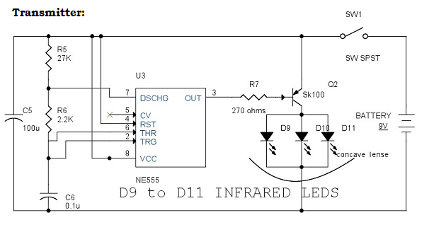
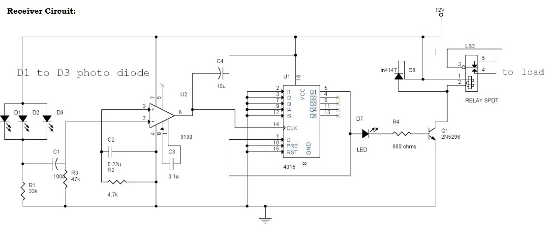
Circuit Explanation:
- In the receiver section there are 3 photodiodes which will detect the infrared signals from the receiver and produce leakage current to the capacitor C1. This current is given to the inverting input of 3130 IC which will get triggered by this current and give amplified output. Remaining all other pins are connected to the ground.
- R2 and C2 are used to stop the unwanted signals from triggering the IC. C3 is used for high gain which is used as comparator amplifier.
- The output of IC3130 is given to the pin14 CLK of Johnson counter 4018. The output of 4018 IC will go high by applying successive clock pulses.
- The resistor R4 is used to stop loading the transistor. The transistor will get ON when the output of 4018 is high and drive the relay to operate in 12V. The diode D4 will protect the relay from reverse current.
- The relay will switch ON or OFF the appliance that is connected to it. LED will act as a visual indicator and also stops the reverse voltage which will effect the counter.
- In the transmitter section, the 555 timer is configured in astable mode and resistors R5, R6 and capacitor C6 are adjusted to give the 5Khz operating frequency.
- When the switch is ON, the capacitor C6 will get charged and when the switch is OFF, it will be discharged through R6 and 555 timer internal transistors. When switch on the 555 timer, output pin3 will be high this will trigger the transistor SK100.
- Resistor R7 is used to stop loading of transistor. When transistor is ON, the infrared diodes which are connected to it will produce high intensity invisible infrared beam which should be given to the photo diodes of receiver.
Note:
- Operating voltage can be between 6V to 15V.
- Relay voltage rating should be equal to the main power supply.
- Heat sink can be attached to the transistor SK100 for compensating the heat dissipation.
- Concave lens is used for producing the strong rays of high intensity.
- The disadvantage in the circuit is switching time between the transmitter and receiver (if we produce the signal from transmitter, again we have to produce the signal after 5 to 6 seconds). Rapid switching like regular remote cannot be done.
Applications of Infrared Remote Control Switch:
- This circuit can be used for switch ON or OFF the TV, radio, washing machine and any electronic appliances.
- By using the relative relays, we can even switch ON or switch OFF the motor appliances also.
With technological advancements in consumer electronics, nowadays almost every appliance in our home is remote controlled.
Managing a different Remote (average figure) for TV, AC, Fan, DVD, DTH, etc., is quite difficult. What if we could have only one remote capable of working as a dedicated remote for any appliance any time?

Presented here is such a device based on Arduino that can act as Remote control for any appliance when needed.

The remote controls for electronic appliances use IR (Infra-Red) communication technique. A specific code is assigned to each key of the remote , based on a standard protocol.
There are various protocols designed by manufacturers, such as NEC, Sony SIRC, Philips RC5, Philips RC6; each carrying a different coding scheme. For example, in NEC protocol based remote, 32-bit code is transmitted, whereas in SONY, 12-bit code is transmitted.
Basically, these codes are nothing but pulses with two levels viz. High and Low. The duration of each pulse is in milliseconds, which is decided by the manufacturer.
The frequency at which the signal is modulated is standardized to 38 kHz. To prevent interference from IR sources such as sunlight or lights, the LED is not turned on steadily, but is turned on and off at a modulation frequency (typically 36 or 38KHz). Thus every receiver must be capable of receiving a 38 kHz signal effectively. A very simple and reliable device for IR signal reception is TSOP17XX, where XX denotes the frequency to which it responds. TSOP1738 is commonly used in IR receiver applications.
TSOP 1738
The TSOP is a miniaturized receiver for infrared remote control systems. PIN diode and preamplifier are assembled on lead frame, while the epoxy package is designed as IR filter. The demodulated output signal can be directly decoded by a microprocessor. TSOP is the standard IR remote control receiver series, supporting all major transmission codes. Its output is Active Low.

The LED Metronome is a modern interpretation of a classic device which is a staple of music teachers, students and composers everywhere. This circuit uses 12 LEDs to simulate the sweeping motion of the pendulum and a speaker with a simple amplifier to generate a tick as the LEDs at the end of the arc are struck. It is adjustable from about 40 BPM to just over 200 BPM. When made in a Lexan or Plexiglass case it can add a fun ultra-modern touch to music practice (though most music teachers agree that you should never rely on a metronome to keep your beat).
Schematic |

Parts |
|
Notes |
- The circuit will reliably run from 6 to 12V. A typical 9V battery will be drained in several days by the LEDs with constant use. A 6V pack made from AA, C or D cells will last much longer.
- The circuit will need some calibration before use. Calibration is fairly easy and accomplished by using a stopwatch to count the number of beats. You'll want to calibrate for 60 BPM (one per second), 120 BPM (two per second) and 180 BPM (3 per second). Just use your stopwatch to find the points of R2 that correspond to those beat rates and the mark the dial appropriately. Next find 90, 150 and 210 BPM. By that time you should then be able to evenly mark the remaining positions on the scale.
- Blue LEDs need about 5V to light, so if you intend to use blue you will need to remove R5.
- For an ideal metronome effect, the LEDs should be arranged in an arc.
IR Remote Switch Circuit
ON 9:37 PM 0 COMMENTS
This circuit lets you control any line powered electrical device (a lamp, television, fan, etc.) using any infra-red remote control. Almost everyone these days has a pile of old IR remotes left over from appliances they have long ago disposed of them. With this circuit, you can put them back into use. The circuit looks for any modulated IR source and uses it to control a TRIAC, which then switches any appliance connected to it's socket. For example, you can use it to control the room lighting in your home theater setup using any of the remotes you already have. The circuit is powered using a simple transformerless power supply from the line itself, making it compact and easily built into a light switch, wall box, power bar or even the appliance you wish to control.
Schematic


Schematic
Printed Circuit Board Layout |
Printed Circuit Board Parts Placement |
Parts |
|
Notes |
- Under normal circumstances, Q1 should not need a heatsink.
- The circuit is designed for a supply voltage of 120V.
- The printed circuit pattern is reproduced here larger then real life for clarity. It will need to be resized to the scale at the bottom of the image if you intend to transfer it to a board.
- The circuit functions as an on/off flip flop. Illuminate it with your remote once to turn it on, then again to turn it off.
This IR remote extender can increase the range of most simple IR remotes (those operating on a 40KHz modulation) a significant distance. In use, the remote is pointed toward the detector on the circuit, and a button is pressed. The Sharp IR detector then decodes the 40KHz modulated signal into a series of pulses, which trigger a 555 timer. The 555 outputs pulses which are re-modulated and used to drive an IR LED. The circuit is excellent for use in a large room like a presentation hall where a typical IR remote is a bit weak. By extending the wires to the output LED (using shielded cable) you can control a device where line of sight isn't available (such as a wall full of TVs in another room).
Schematic

Notes
- Only the CMOS TLC555 timer can be used in this circuit. The original NE555 cannot operate reliably at 40KHz. Acceptable substitutions are shown in the parts list.
- Almost all powerful IR LEDs can be used for D1 if the appropriate value of R5 is chosen.
- To calibrate the circuit, use a frequency counter. Connect it in parallel with D1 and then ground the base of Q1. Adjust R3 for 40KHz on the counter. If a counter is not available, you will just have to point a remote at the circuit, press a button, and then adjust R3 until it works. This can take a few tries as not all remotes transmit continuously.
- If you intend to remotely mount D1 any great distance, you will need to use shielded cable. Connect the shield to circuit ground.
Parts
| R1, R6 | 2 | 10K 1/4W Resistor | |
| R2 | 1 | 1K 1/4W Resistor | |
| R3 | 1 | 10K Linear Pot | |
| R4 | 1 | 2.2K 1/4W Resistor | |
| R5 | 1 | 47 Ohm 1/4W Resistor | |
| C1 | 1 | 0.01uF Ceramic Disc Capacitor | |
| Q1, Q2 | 2 | 2N3904 NPN Transistor | |
| D1 | 1 | IR LED | Radio Shack 276 143C |
| U1 | 1 | GP1U52X IR Module | |
| U2 | 1 | TLC555 CMOS Timer | LMC555, 7555 |
| MISC | 1 | Board, Sockets For U2, Wire |
Schematic

Notes
- Pushing and holding S1 causes the LEDs to rapidly cycle. Releasing the button locks the pattern and shows a number from 1 to 6.
- When building the circuit, make sure to position the LEDs as shown on the schematic. Otherwise the pattern of the dice will look weird.
- Two circuits can of course be both powered by one switch to make a dual dice.
Parts
| R1, R5, R6 | 3 | 22K 1/4W Resistor | |
| R2 | 1 | 10K 1/4W Resistor | |
| R3 | 1 | 4.7K 1/4W Resistor | |
| R4 | 1 | 150K 1/4W Resistor | |
| R7 - R13 | 7 | 330 Ohm 1/4W Resistor | |
| C1 | 1 | 1uF Electrolytic Capacitor | |
| C2 | 1 | 4.7uF Electrolytic Capacitor | |
| D1 | 1 | 1N4148 Signal Diode | |
| D2 - D8 | 7 | Red/Green/Yellow LED | |
| Q1 | 1 | 2N3904 NPN Transistor | |
| U1 | 1 | 555 Timer IC | |
| U2 | 1 | 74LS192 4 Bit Counter IC | |
| U3 | 1 | 74LS08 Quad Intengreted AND Gate IC | |
| S1 | 1 | SPST Momentary Pushbutton Switch | |
| MISC | 1 | Board, Wire, Sockets For ICs, Case |
++++++++++++++++++++++++++++++++++++++++++++++++++++++++++++++++++++++++
Count Rolling Technological miracles Electronic
++++++++++++++++++++++++++++++++++++++++++++++++++++++++++++++++++++++++
Take off is one of the educational intitution and we will train the people and we will give 100% placements .and we have the electronice peojects and electronics circuit projects .https://takeoffprojects.com/electronics-projects
BalasHapusTake off is one of the educational intitution and we will train the people and we will give 100% placements .and we have the electronice peojects and electronics circuit projects .https://takeoffprojects.com/electronics-projects
BalasHapusElectronics projects for students