fuse wiper car and airplane value is 15 until 30 Ampere cause AMNIMARJESLOW GOVERNMENT 91220017 RD 4 ZERO windows gate and Portal Washer LJBUSAF AMNI 02 09 60 00 14 BUSI / BUSY LIGH TO TAB FIRE $$$ Y O JES NI MO WO EE 🔃🔃🔃🔃🔃 TT 🔃🔃🔃🔃🔃 0201 11 $$ 8173 $
🔃🔃🔃🔃🔃 🔃🔃🔃🔃🔃
X . XXX Windshield Wipers & Washers
It can be frustrating when your vehicle keeps blowing your windshield wiper and washer fuses. Several reasons exist for a blown fuse for windshield wipers and washers.
Current
The windshield wiper or washer motor could be drawing too much current. To see if this is the problem, disconnect the wiper motor for a little while. If the fuse doesn't blow, the motor is drawing too much current.
Interference
Another reason for a blown fuse for your windshield wipers and washers may be debris or ice built up around the wipers. Look around the wipers and see if there is anything that could be interfering with the arm movement, and remove it. Test to see if this was causing the problem.
Warning
If you have a fuse that keeps blowing, do not replace it with a larger, higher amp fuse. The size of the fuse is predetermined to help protect the circuit. If a larger amp fuse is placed where it is not needed, it will not stop the flow of the current when necessary.
F150 2005 Wiper Fuse Location
by Thomas West
Although the Ford F-Series trucks had been around since the late 1940s, the F-150 nameplate did not surface until 1975 as a heavier-duty version of the F-100. Eventually, F-150 sales surpassed the F-100 and the F-150 name stuck. The F-150 was restyled in 2004, so little changed on the 2005 models. Fuses located in the fuse box protect the electrical circuits of the 2005 F-150. If the windshield wipers or any other electrical components stop working, check the fuse to make sure it has not burnt out.
Open the passenger-side front door. Locate the access panel for the fuse box under the dashboard.
Pull the access panel away from the dashboard until the built-in clips release. Place the panel aside.
Locate the pull-tab on the fuse box cover revealed after removing the access panel.
Place a finger behind the pull tab. Place your thumb on the fuse box cover just above to tab. Pull the tab straight out while keeping pressure with your thumb. Remove the cover from the fuse box when it releases and place it aside.
Locate the combination windshield wiper and windshield wiper washer fuse in position number 113, which is third up from the bottom on the far right-hand side of the fuse box.
Tip
checkNote that the wiper fuse has a 15 until 30-amp capacity. To check the fuse, locate the fuse puller on the inside of the fuse box cover. Remove the puller and place it over the wiper fuse. Squeeze the puller over the fuse and pull it straight up. Examine the wire embedded into the fuse through the transparent plastic housing. If the wire is burnt in half, then the fuse has blown and needs replacing. Replace the fuse by pushing it down into the fuse box until it has fully seated.
If We Windshield Wipers Aren't Working
Good windshield wipers aid safe driving. Torn wiper blades, a bad wiper motor, a blown fuse, or heavy snow may be why your wipers are not working
Keeping your windshield clear is paramount to a safe driving experience. If you don’t have a clear view of the road ahead of you, it's more difficult to avoid an accident, an object on the road, or a defect in the road surface such as a pothole.
In order to keep your windshield clear, your windshield wipers need to operate properly. At times it may seem like your windshield wipers aren’t working as they should, or they may stop working altogether. There are several reasons why your windshield wipers aren’t working.
Here are the top 5 reasons your wipers aren’t working:
Your wiper blades are torn. The condition of your wiper blades is directly related to how well your windshield wipers work. If the rubber edges on your wiper blades are torn, the wiper will not make proper contact with the windshield to clear moisture or debris away. The small gap left by the missing rubber can actually trap additional dirt that may scratch or gouge your windshield glass. Replace torn wiper blades immediately so your visibility isn't compromised.
The windshield wipers have ice or snow on them. Windshield wipers are able to remove small amounts of snow from your windshield, but heavy, wet snow needs to be cleared by a snow brush before operating your wipers. Wet snow can be so heavy on your wipers that your blades can get bent, the wiper arms can skip or strip at the pivots, and the wiper motor or transmission can get damaged. Remove heavy snow from your windshield before using your wiper blades. If you live in an area that experiences heavy snowfall, like Spokane, Washington, or Salt Lake City, Utah, you may want to invest in winter wiper blades.
The wiper motor has failed. The windshield wiper motor is an electrical motor. As an electrical component, it can short out or quit unexpectedly and require replacement. If that happens, your windshield wipers will not work at all and you won’t be able to clear any water, dirt, or snow that ends up on your windshield. Replace the windshield wiper motor right away.
The windshield wiper fuse is burnt out. When the windshield wiper motor is overloaded, the associated fuse burns out. The fuse is designed to be a weak spot in the windshield wiper circuit. That way, if the motor is overloaded for any reason, the fuse will burn out first, instead of the more expensive wiper motor. If the wiper motor fuse burns out, check for any obstructions that may cause the motor to be overloaded. Heavy snow on the wiper blades or a wiper blade or arm caught on something or snagged together can cause the fuse to blow. Clear the obstruction and replace the fuse. If it still doesn’t work, have it looked at by a professional from YourMechanic.
Wiper pivot nuts are loose. The wiper arms are connected to the wiper transmission by a nut on a pivot. The pivots are usually splined with a stud protruding. The wiper arms are splined as well and have a hole through the base. A nut tightens onto the pivot stud to hold the wiper arm tightly to the pivot. If the nut is a little loose - which is common - the wiper motor will turn the pivot but the wiper arm will not move. You may see it slightly move when the wiper direction changes, but it does not wipe the windshield. You may notice only one wiper working while the other stays at the bottom. If you have this issue, make sure the wiper pivot nuts are tight. Otherwise, have a professional mechanic from YourMechanic check your wipers and repair them.
X . XXX Airplane and Aircraft Instrument and control for feedback Automatic system Electronic
Go permalink
All of them? If you're talking about a commercial airliner, then there's hundreds and hundreds. There are big, fat manuals describing what they all do. But, since you asked, buckle up.
Every airplane is different. Unlike learning to drive a car, you can't just hop from one plane to another. A pilot needs familiarization (and in some cases, a whole new type of license) to fly a different kind of plane. Some are piston-powered; some are jet-powered. Some have electrically-driven controls; some are hydraulically-driven. Some have emergency oxygen; some don't. And so on. All the switches, dials, and knobs in the cockpit control the various aircraft systems, and every aircraft has different systems.
Let's take a very popular airliner, the 737. And of course, different 737s are different, so let's just invent a 737 that we can use. A typical one. Here's a photo of a 737.
Pretty typical small-body airliner. For our example, we're going to be flying a737-600, a modernized 737 with glass-cockpit displays and digital avionics.
Advertisement
So, before we can talk about what all the switches in the cockpit do, we need to know what systems the 737-600 has onboard. So without further ado, here is a non-complete list of all the systems that the pilot or copilot might need to manage: Engine: Our 737 has two CFM56-7 turbofan engines with thrust-reversing capability. The engines are started by an APU (auxiliary power unit) — the APU is itself a mini-jet engine that is used to start the two big boys under the wing. (The APU is started by the battery, if you're curious.) Fuel flow to the engines is electronically controlled. Fuel: The 737 has three fuel tanks: one in each wing, and a center tank in the fuselage. Electrically-powered fuel pumps transfer fuel from the tanks to the engines. Each tank has two redundant fuel pumps, for a total of six. The center tank drains first, then the wing tanks. Normally the left center fuel pump sends fuel to the left engine, and vice versa, but there is a cross feed valve that opens to allow the left center pump to provide fuel pressure to the right engine in the event the right center pump fails (or vice versa).
Advertisement
Hydraulics: The engines power three redundant hydraulic systems (systems A and B, and the standby system) which actuate the flight controls (elevators, rudder, ailerons) that maneuver the aircraft in flight. The hydraulic system also powers the landing gear, flaps, and slats, thrust reversers, as well as a few other minor things. System A and B each power a subset of the preceding list, with the standby system providing emergency hydraulic power to the critical systems only. Electrical: Each engine (including the APU) has its own generator that can power the aircraft's electronics (lights, avionics, galley, in-flight entertainment, etc.). When the engines are off, the aircraft uses an onboard battery to power its systems. There is also a standby battery in the event the main battery is drained. The aircraft can also accept external ground power from a mobile generator. Each electrical source (battery, generator, ground power) can be hooked up to one of two transfer buses that move the electricity to aircraft systems. Typically in flight each engine generator is hooked up to one of the transfer buses. In the event one electrical source (APU, battery) must power both transfer buses, a bus tie system connects the two buses. Bleed air: Bleed air (siphoned from each engine) powers the air conditioners and anti-ice system, and pressurizes the hydraulic and fuel pumps. The airplane is split into two separate "zones" which can have their own temperature settings. The aircraft can also accept external air from a mobile air cart.
Advertisement
Oxygen: The 737 has two independent oxygen systems — one for flight crew and one for passengers. In the event of depressurization, the oxygen masks will drop and oxygen canisters will supply pressurized oxygen to the passengers and flight crew. Navigation: The 737 is equipped with two independent GPS antennas and three IRUs (inertial reference units). An IRU is a gyroscope that records changes in acceleration. By integrating these changes over time, the airplane can track its position, though it gets increasingly inaccurate over time. Radios: The 737 has three communication (COMM) radios and three navigation (NAV) radios. The COMM radios let the pilot talk to ATC and the NAV radios let the pilot navigate to or from ground radio navigation stations. There's also an onboard weather radar that sends out radio waves ahead of the plane looking for storm clouds.
OK, let's get started. I'll start with the pilot's side of the main panel. The two main displays in front of the pilot are the PFD (primary flight display; left) and ND (navigational display; right). The pilot and copilot each have a set, and there is a pair of shared DUs (display units) in the center (arranged top-and-bottom). Each can independently display one of a few different screens of information. In the above picture, the top DU is showing engine information and the bottom DU is blank.
Advertisement
The information shown on the PFD is the airspeed tape (left side), the attitude indicator (center — shows the sky and ground pictorially), the altitude tape (right side), and the rate-of-climb indicator (far right). Along the top, the current autopilot mode is shown (autopilot is currently off). On the bottom is the heading indicator. The yellow text are some warnings and the green text is the altimeter setting (more on that later). The purple text is the autopilot speed and altitude settings (more on that later too).
The navigation information shown is the current heading (solid line) and the course dialed into the FMC (flight management computer; more on that later — it's the dotted purple line). Two white blocks of text show information about the next waypoint and and some general position information. The green text shows information about how accurately the jet can guess its position.
The engine information shown: On the top left are two dials; they indicate the N1 setting for the left and right engine. N1 is a measure of engine power — at 100% N1, the engine is producing maximum power (right now the engines are at 22.5% N1). The second row shows the engine's EGT (exhaust gas temperature, currently 411 °C), another measure of engine power and also an important thing to monitor — if the exhaust gas is too hot, you're in trouble. To the right of the dials is a grid where engine warnings would pop up. On the bottom right are the fuel gauges; it shows the fuel in each of the three tanks and the total fuel onboard (40,200 gallons).
Advertisement
Between the top DU and the pilot's ND are the standby flight instruments. In the event that the PFD fails, the pilot can still get critical flight information from these backup instruments. The top one is the standby flight display — it looks just like the regular PFD. The big white knob sets the altimeter setting (again, more on that later). The + and - buttons on the right side control brightness. The APP button on the top-left toggles between two different displays relating to landing the aircraft: approach and back-course. When these modes are active, the pilot gets additional help in guiding the plane down to the runway. The HP/IN button to the right of that button toggles between American and European units. The RST button on the bottom left resets the instrument to displaying straight and level, in case it "tumbles" during heavy maneuvering. (You should only press this button when the plane actually isstraight and level.)
Below the standby flight display is the standby HSI (horizontal situation indicator — it's a heading indicator that also has the ability to navigate you to a waypoint). The knob on the standby PFD sets the altimeter setting (again, more on that later). The two dials below the standby HSI set the course that the pilot would like to fly to or from one of two radio navigation fixes he would have tuned in (e.g., I wish to fly to the Oakland VOR on the 090° course). The dials show the course you dialed in with the knobs, and indicate how accurately you are flying that course.
Above the standby attitude indicator is a small dial labeled YAW DAMPENER. The yaw dampener helps the pilot smooth out turns by coordinating aileron and rudder input. When the bar is centered, the turn is smooth. When the bar slides left or right, the yaw dampener needs to add right or left rudder to the turn to smooth it out. This lets the pilot check if the yaw dampener is working properly.
Advertisement
There is one little light above the PFD; this is a warning light that tells the pilot when that the below-glidesope alert is active. (The glideslope is the proper glide path down to a runway. If you're too far below it, you're going to get leaves in your engines.) Pressing the light inhibits the warning, in case the pilot really does know what he's doing.
To the right of that light, above and between the PFD and ND, are two knobs; these control what systems are linked to the pilot's displays. Normally the left screen shows the PFD and the right screen shows the ND, but if one of your screens fails, you could switch up which screen displays which system. These knobs let you do that.
To the right of those knobs are a set of three lights in a well; these light up to tell the pilot when the autopilot has disconnected, the auto throttle has disconnected, or there is an error on the FMC (again, FMC explained later). The switch to the right tests the lights. The switch to the right of that switch is the master warning lights switch; it controls the brightness of all warning lights, and tests all warning lights.
Advertisement
Below the well are three more lights. They light up to tell the pilot when the speed brake is extended, when the speed brake should not be extended, and when the autopilot is failing to trim the aircraft properly (an aircraft is in trim when it can fly straight and level without continuous input from the pilot or autopilot; an aircraft out of trim will slowly pitch up or down).
To the left of the pilot's PFD is a digital clock with count up timer and sweep second hand. The CHR button on the top left of the clock face starts/stops/resets the chronometer. The two buttons on the top right are used to set the time and toggle between local time/UTC time/date display. On the bottom-left, the two buttons control the elapsed time counter, which is used to time the entire flight. Lastly, on the bottom-right, the + and - buttons are used to set the time.
Below that is a switch that toggles between the normal (hydraulic system A) or alternate (hydraulic system B) nose wheel steering (NWS) system. (NWS turns the nose wheel on the ground and allows the plane to steer during taxi.)
Advertisement
Alright, next up, the knobs below the pilot's PFD and ND. On the very left is a pull-lever labeled FOOT AIR, to make the pilot's feet comfortable, followed by WINDSHIELD AIR, which defogs the main windows.
To the right are five knobs. They control the brightness of the four displays (PFD, ND, upper DU, and lower DU) and the brightness of the panel itself (flood lights that light the whole panel).
Then to the right we've got two more knobs, that control the brightness of the background lights, and another set of flood lights that light the top portion of the panel (which we'll see later).
Advertisement
Now to the right of those knobs we see a small screen with a keyboard. That's the FMC, or flight management computer. This is a computer into which the pilot enters the route he wants to fly, the altitude he wants to fly it at, and all sorts of other information about the flight. From that the computer calculates the best speed to fly each leg of the flight, how long it will take, whether there's enough fuel, etc. The pilot can also enter in restrictions (can't be above 250 knots below 10,000 feet, for example), and the autopilot will obey those restrictions. The FMC has a multitude of other functions, like finding nearby airports in an emergency, or calculating holding patterns, etc. There's pages and pages of features.
To the right of the FMC is the lower DU, and then the copilot's very own FMC. There's some stuff above his FMC that we can't really see well, so let's take a closer look to the right of the previous image.
The big round handle is the landing gear lever. Pull it up and the gear retracts; push it down and the gear extends. Above the lever are three landing gear lights. They're green when the gear is down, red when the gear is in motion or not fully extended, and unlit when the gear is up. It's typically a good idea to check for "three green" before landing.
Advertisement
To the left of the gear lights is the flaps indicator. The flaps are a pair of flat surfaces on each wing that can extend outward to increase the surface area of the wing. This allows the plane to fly at slower speeds (say, for landing). Right now the needle shows the flaps at 0° (fully retracted). They can be extended all the way out to 40° for very slow landings.
To the left of the flaps indicator are the auto brake controls. The auto brake can automatically start braking after landing. The top light illuminates when the auto brake disarms due to a malfunction, reminding the pilot that it's now his job to stop the plane. The middle knob sets the braking intensity, from OFF (no auto braking) up to 3 (hard braking), with a special RTO setting (rejected takeoff — hold on to your hand rests).
The two lights below the flaps indicator light when the flaps are moving or extended, respectively. The light below the auto brake knob illuminates when there is a malfunction in the anti-skid system, warning the pilot not to apply excessive brake pressure and cause a skid.
Advertisement
To the left of all that are a pair of small knobs, a switch, and two pushbuttons. The right knob controls where the aircraft gets its calculated reference airspeeds — important airspeeds that must be called out during takeoff. They can be automatically calculated by the FMC, or as a fallback, entered manually using this knob. The left knob controls what max. N1 limit is displayed on the upper DU. Like the reference airspeeds, it can be automatically calculated by the FMC or manually entered. The setting appears as a red line on the N1 dials displayed below on the DU.
The FUEL FLOW switch below the N1 setting knob controls the fuel flow indicator; normally it shows the fuel flow rate, but can temporarily act as a fuel "triptometer" — showing fuel used since the last reset, and marking a reset point.
The three buttons to the right of that switch control what's shown on the lower DU, either engine information (ENG) or information on the aircraft's other systems (SYS). The C/R button is cancel/recall — press it once to "cancel" any warnings shown on the DU (makes them disappear), and press it again to "recall" those warnings (makes them reappear).
Advertisement
To the right of the landing gear lever are the copilot's PFD and ND, the copilot's cockpit illumination controls, and air controls (not shown). They mostly mirror the pilot's.
OK, let's move on to mode control panel (MCP). It sits on top of the main panel:
On the left side are the controls for the pilot's ND. The top-left knob (MINS) is where the pilot dials in the minimum approach altitude. This is the lowest the pilot can go before he must see the runway to land. If he can't see the runway, he has to abort the landing. Setting this knob will let the plane say "MINIMUMS" when the pilot reaches this altitude, as a reminder. Then, going right, we've got an FPV button that toggles display of the flight path vector on the PFD (basically a little circle showing you where your airplane is trending; e.g., if it floats above the artificial horizon you know your plane is climbing). Then a button (MTRS) that toggles between metric and English units for international flights. And lastly a knob (BARO) for changing the altimeter setting: that's the outside surface air pressure. The pilot needs to do this so the altimeter indicates an accurate altitude.
Advertisement
Second row: The first switch (VOR1/ADF1) toggles the left data block on the ND between VOR and ADF information. (VOR and ADF are two kinds of radio navigation.) Then we've got a knob that sets which of the different screens the ND is displaying (currently the MAP screen). The ND can show an overhead map view (as shown), or a plan view, or an approach and landing view, etc. The next knob over sets the range of the ND (the zoom knob). And then there's another switch that's like the VOR/ADF switch on the left side, but for the right data block. (These data blocks are not currently shown ND.)
The bottom row of buttons toggle on and off the display of different "data layers" on the ND. In the photo the ND is pretty sparse — it's just showing the compass rose and course line. The pilot could use these buttons to show weather radar, nearby airports, topographic terrain, etc.
To the right of that cluster, spanning the remaining width of the MCP, are the autopilot controls. When the pilot is not actually flying the airplane by grabbing the yoke, he is dialing in instructions to the autopilot using this panel.
Advertisement
At the very left side of the MCP is the course knob and window. This knob sets an inbound or outbound course to fly towards a radio navigation facility (e.g., fly to the Newark VOR via the 270° radial). Below and to the right of that knob is the F/D (flight director) switch. Turning on the flight director is like "assisted autopilot": The autopilot doesn't actually fly the plane, but shows you on the PFD what you should be doing to fly the plane in the way it wants you to. It's extra guidance for the pilot who still wishes to hand-fly.
Just above the F/D switch is a tiny little light labeled "MA" (for master — though it's unlit so you couldn't tell). There are actually two of these lights; one on the left side and one on the right — you can see the right one on the other side of the photo. These correspond to the two FCCs (flight control computers) that power the autopilot. If the left light is on, the left FCC is doing the F/D calculations. If the right is on, the right FCC is doing the F/D calculations. Normally the left FCC manages the pilot's F/D, but if the pilot's FCC fails, it could be managed by the copilot's FCC.
Moving over to the right, we've got the A/T (auto throttle) arm switch. The auto throttle can control the throttles automatically to maintain a set airspeed or N1. To the right of the switch is a knob that dials in the airspeed/N1 setting, and above it a display showing the current airspeed/N1 setting. There are lines moving out to the bottom-left and bottom-right, connected to buttons. These enable the different auto throttle modes — N1 (maintain an N1), SPEED (maintain an airspeed), and LVL CHG (level change; sets throttles appropriately for climbs and descents).
Advertisement
There's also a small button to the left of the knob called C/O (changeover), which toggles the display between airspeed (in knots) and Mach number. At higher altitudes, speed in Mach becomes more important than speed in knots.
The other small button to the right of the knob is the SPD INTV (speed intervention) switch. If your FMC is calculating your speed for you, but you temporarily want to maintain a different speed, press this button and dial in your speed. Press it again to return to flying the FMC's calculated speed.
Above that button is the VNAV button, which turns on the vertical navigation autopilot mode. This mode will fly the vertical profile programmed into the FMC, beginning climbs and descents as the FMC commands.
Advertisement
To the right of the VNAV button is the heading knob and related buttons and window. This knob is used to set a heading for the autopilot to fly. The button just below the knob turns on heading mode, commanding the autopilot to fly that heading.
To the right of the knob is a row of three buttons. The top turns on LNAV (lateral navigation) mode. This mode flies the plane through the waypoints programmed into the FMC. Turning on both LNAV and VNAV mode will have the plane fly exactly the 3D route programmed into the FMC. The middle button turns on VORLOC mode, where the plane flies to a VOR (radio navigation fix) using the onboard nav radio and the course dialed into the course window. The bottom button is APP (approach) mode, where the plane flies an ILS signal down to a runway. ILS is a very accurate radio navigation system that can guide a plane precisely onto a runway for landing.
Next column to the right is the altitude setting. We got a knob and a window for setting the altitude, and two mode buttons: ALT HLD (altitude hold), and V/S, which holds a specified vertical speed. To the right of the knob is a small ALT INTV (altitude intervention) button that works like the SPD INTV button. Then we got a knob and a window for dialing in a desired vertical speed in feet per minute.
Advertisement
Moving right is a grid of four buttons. These control the two autopilot computers (A and B). The top row of buttons turn on autopilot command mode (where it has total command over the aircraft), and the bottom row turns on CWS (command with steering) mode. CWS is a special mode where the pilot pushes the controls to get the plane flying in the way he wants, and then releases the controls — the autopilot then takes over the flying. There are two redundant autopilot systems, and both must be active to make an autopilot-controlled approach and landing.
The big bar below the grid of buttons disengages the autopilot and gives the pilot full control of the aircraft. To the right of that grid are some duplicated controls from the left side that are in easier reach of the copilot.
The other panel we can see in this image is the Ground Proximity Warning System (GPWS). The panel is below the copilot's ND, containing three large black switches.
Advertisement
The GPWS warns the pilot when it detects that the aircraft may hit the ground. The three switches are used to turn on and off three types of ground-proximity audio warnings: "TOO LOW - FLAPS" (when the plane thinks you may have forgotten to extend your flaps before landing), "TOO LOW - GEAR"(when the plane thinks you may have forgotten to lower your gear before landing), and "TOO LOW - TERRAIN" (when the plane thinks you may have forgotten about that mountain between you and the runway).
Above and to the left of the switches is a warning light indicating when the GPWS is inoperative, and a SYS TEST button that tests the GPWS.
Now let's look above the main panel, on the glare shield:
The red Fire Warning light is bad news when it lights up, but you can silence the alarm bell by pressing it. The yellow Master Caution light is also bad news; pressing it "acknowledges" the caution and turns off the light. To the right of the Master Caution light is a grid of lights that indicate what is generally wrong with the airplane. (Nothing is illuminated right now, but examples are FLT CONT [flight controls] and ELEC [electrical system].) The copilot has his own Fire Warning and Master Caution lights, as well as a separate grid of different annunciators.
Advertisement
The CLOCK button on the very left operates the chronograph, same as the CHR button on the clock face.
Let's take a look at what's to the left of the pilot's seat:
The wheel on the right side of the image is the tiller wheel, used to steer the airplane on the ground. Below it are two knobs; the forward one controls the brightness of the map light (the red-capped light on the left side of the image). The rear knob has no function.
Behind the knobs is the pilot's emergency oxygen mask.
Let's move on to the throttle console now!
At the center are the throttles. Push forward to burn more gas, pull back to save money. There's one for each engine. There are also paddles behind each throttle lever that control the thrust reversers. Pull up to apply reverse thrust during landing. There are buttons underneath each throttle grip (not shown) that engage TO/GA (takeoff/go-around) mode. Press either button and the throttles automatically set for either a takeoff or an aborted landing. The black buttons on the side of each throttle grip cause the auto throttle to disengage, giving throttle control back to the pilot.
Advertisement
The pair of levers below the throttle are the fuel cutoff levers. Pulling either of these levers down will cut off fuel to that engine. They're used to shut the engines down in an emergency or as part of a routine shutdown.
The big wheel is the trim wheel. If the plane is floating up hands-off, push the wheel forward to apply forward trim. And vice versa. Nurse the wheel as needed to get the plane to fly straight without any pressure on the yoke from the pilot. To the right of the trim wheel is the trim indicator.
Next to the trim wheel is the parking brake lever, and behind it a light that illuminates when the parking brake is set. Also next to the trim wheel is the speed brake lever — pull back to deploy the spoilers and slow down; push forward to clean up the plane and speed up.
To the right of the throttles is the flap lever, which sets the flap position.
Below the flap lever are the stabilizer trim cutout switches. There's one switch for the autopilot's automatic control of trim, and another switch for the pilot-controlled electric trim system. If either system were malfunctioning and trimming the aircraft incorrectly, you could disable it and just trim the plane manually using the big trim wheel. Note that these are backup trim cutout switches — the normal trim cutout switch is on the yoke.
OK, let's move away from the throttle quadrant to the bottom portion of the center console. At the top are the bright red fire extinguisher handles, labeled "1" and "2" (for engine 1 [left] and 2 [right]), and "APU" for the APU fire extinguisher. To the left of the engine 1 extinguisher is the OVERHEAT switch, which selects between redundant A and B engine overheat detection circuits. Below that is a light that illuminates if an overheat is detected in the left engine, and below that a switch that tests the A and B detection circuits.
Advertisement
Between the engine 1 and APU handles are lights that warn of: a fire in the wheel well, a fault in the A or B fire detection circuit (depending on the position of the OVERHEAT switch), a fault in the APU fire detection circuit, or a discharged APU bottle (you only get one!).
Between the APU and engine 2 fire extinguisher handles is a similar set of test switches and warning lights for the right engine, and a big black BELL CUTOUT button (obscured) that silences the fire warning bell if the pilot should get sick of it. To the right of the engine 2 handle is the bottle test switch and lights that tell the pilot that each of the three extinguisher bottles is working properly. There are also a pair of lights indicating that the left or right bottles have already been used.
Moving down to the very top-left side of the center console is the COMM1 radio panel. The left window shows the active frequency: the frequency the pilot would be talking over if he were to key in the mic while COMM1 was set. Then to the right we have the standby window, which is where the pilot dials in the next frequency he wants to talk to. When he's ready to switch frequencies, he presses the transfer button in between the two windows, and he's on a new frequency. The two knobs set the larger and smaller digits of the standby frequency. There's also a test button and an on/off button below the right and left windows, respectively. The grid of six buttons in the bottom center choose which radio the COMM1 panel is connected to: There are three VHF radios, two HF radios, and an AM radio. The HF SENS knob is used to set the sensitivity when COMM1 is connected to the HF radio: HF is a very long-range radio system used in overwater flights, and can require fine-tuning of sensitivity.
Advertisement
Moving right, we have the cargo file panel. We have two green lights that light up when the TEST button below it is held down, to show that the two cargo fire extinguisher bottles are working. We got two small knobs that choose between each of two fire detection circuits for the forward and aft cargo locations (so two circuits per location, two locations total). To the right is a light that illuminates if a fault is detected in any fire detection circuit. Below the knobs are two lights that illuminate should a fire be detected in the forward or aft cargo compartment. To the right of those lights is a guarded button; flip the guard and press down to extinguish the cargo fire. It doubles as a light telling you you've already discharged your bottle.
To the right of that is the COMM2 radio, which works the same as the COMM1 radio.
Below the COMM1 radio control is the NAV1 radio control. This works like the COMM radios except the pilot doesn't talk over the radio; the airplane uses the radio signal to navigate to a station. There's a test button that drives the NAV1 needle (on the ND or the backup HSI) to a known heading; if the needle is on that heading, the radio is working.
Advertisement
To the right of NAV1 are the weather radar controls. The left knob sets the gain (sensitivity) of the weather radar, and the right knob is used to tilt the radar up or down, to scan for storm clouds above or below. The buttons select different display modes, such as WX (weather only) or WX+T (weather and turbulence). In case you're curious, the radar can detect turbulence by noticing when rain droplets change direction as they fall.
Then, moving right, we've got the NAV2 radio, same as the NAV1 radio.
Below the NAV1 radio is the audio selector panel. The top row of buttons sets who the pilot is talking to when he keys in the mic. He can talk over COMM1 or COMM2, he can talk to the flight attendants or to all the passengers, etc.
Advertisement
The two rows of knobs below that set the volume for each of the many different radios and other audio sources that go into the pilot's headset.
The bottom right switch is a backup push-to-talk switch for mic keying. (The normal PTT switch is on the yoke.) Move up to talk over the radio, and move down to talk over the intercom.
To the right is the MASK/BOOM switch, which toggles between the oxygen mask microphone and the boom microphone for transmissions. The pilot would only use the MASK position of the oxygen mask deployed in an emergency.
Advertisement
The V-B-R knob controls what audio is filtered out from nav radio stations. In "V", only weather information is heard (which is sometimes broadcast over a nav radio). In "B", both weather information and the morse code identifier is heard. In "R", only the morse code identifier is heard (to verify that the pilot tuned in the correct station, and the station is working properly).
The ALT-NORM switch on the right toggles between normal and emergency mode for the communications system.
To the right of the pilot's intercom controls is the HGS (heading guidance system) controls. The pilot uses this panel to input information into the HGS. The HGS then displays telemetry to the pilot over the HUD (more on that later) to help him land. The pilot presses a button on the left (such as RWY for runway length), then enters the data using the numeric keypad on the right. Once he's entered all the data, the HGS can then help guide him down to a landing. There's also a clear button and brightness controls along the bottom.
Advertisement
To the right is the copilot's mic and intercom controls, which are the same as the pilot's.
Below the pilot's intercom controls is the ADF panel, which controls the ADF, a very old form of radio navigation. The bottom-left knob switches between ADF mode (for navigating to the radio signal) and ANT mode (for listening to the radio signal). The right knob mutes and un-mutes the radio signal. The pilot would listen to the radio signal to hear the morse code and make sure he's tuned the correct frequency, and ergo navigating to the correct station.
To the right of the ADF radio is the transponder controls. The transponder is a device that intercepts an incoming radar beam (from an ATC radar) and sends it back out with information about the aircraft. ATC uses this information to get more information about an aircraft than it could from just an unmodified radar return.
Advertisement
The top left knob selects between one of two redundant transponders. The middle window is the transponder code. Every aircraft is assigned a four-digit code when it's under ATC control; you dial it in with the two knobs below and on either side of the window.
The top right knob turns on the transponder and sets its mode. XPNDR turns on altitude reporting, which sends back the plane's current altitude (which can be hard for radar alone to determine) with the radar beam. TA additionally transmits the plane's unique identifier. And TA/RA will also allow the transponder to receive data broadcast from ATC to all nearby aircraft over the radar beam. This data includes the locations of other aircraft that the radar is picking up.
Note that the four-digit squawk code is different from the unique ID transmitted in TA mode — the four digit squawk code can be reused many times in a day, whereas the unique Mode S ID is assigned once to one aircraft for all time.
Advertisement
The bottom left knob sets whether to use the pilot's or copilot's altimeter when reporting altitude back. The middle IDENT button performs an identification function. This causes the aircraft to "light up" on ATC's radar. ATC will often ask an aircraft to "ident" to figure out who they're talking to. The top middle light indicates a transponder failure.
To the right of the transponder controls, below the copilot's intercom panel, is the COMM3 radio panel, same as the COMM1 and COMM2 panels.
The bottom left panel controls the brightness of the center panel and flood lights.
Advertisement
At bottom center are additional trim controls. The aileron trim controls are on the bottom left, allowing the pilot to trim left-wing-down or right-wing-down if the plane is drifting left or right. The indicator is in on the yoke. The knob on the bottom right is rudder trim, and its indicator is above the knob
To the right of that is the stabilizer trim override switch. In the NORM position, the yoke trim cutout switch is operational. In the OVRD position, the two trim cutout switches on the throttle quadrant (discussed above) are operational.
At the very bottom right are the cockpit door controls. The door can be unlocked, locked, or automatically controlled using the right knob. The two lights indicate when the door is unlocked and when the locking mechanism has failed.
Advertisement
We're almost done — let's do the overhead console! Let's start with the top half.
The red switch at top-left controls the in-flight WiFi; it can be in normal or override-off mode.
Advertisement
Below that switch are the IRU controls. At the top we have a window that displays information, and a knob that controls what information is displayed. It can display the current lat/lon, the wind direction and speed, the airplane heading and speed, etc. All of this information comes from the IRS (inertial reference system).
Below that is a knob that toggles the display between using the left or right IRS (there are two after all). To the right is a keypad used to enter in the initial lat/lon of the aircraft. (Remember that the IRUs only measure changes in position, so without an initial position, they can't give any useful information.) Normally this is done using the FMC, but it's here too as a backup.
Below the IRS panel are some warning lights showing when an IRU has failed, or is on battery backup power, and a pair of knobs that set the left and right IRU mode. IRUs have to spin up and align before they can be used for navigation, a process that takes 10 minutes. So the IRU must first be put into ALIGN mode for 10 minutes or so before it can be moved into NAV mode. If the pilot is in a hurry, he can put the IRU into the emergency ATT (attitude-only) mode, but he will get no position information and only attitude information.
Advertisement
To the left are two slanted sets of lights: That's the leading-edge flaps indicator. The flaps actually have two components: The part that extends backwards and the part that extends forwards (the slats). These lights indicate whether the slats are in motion, extended, or retracted.
Below the slats indicators is a single, lone caution light. It illuminates when the PSEU (proximity switch electronic unit) has failed. The PSEU monitors the sensors that determine if the landing gear is up or down, if the aircraft is flying or on the ground, etc.
To the right of the IRS panel is the SERVICE INTERPHONE switch, which turns on a backup system for talking with the flight attendants. Below that is the DOME WHITE switch, that turns on and off the bright white dome light that floods the whole cockpit. (Not good for night vision.)
Advertisement
Then, one column to the right at the top, is an intercom panel for the observer (a third flight deck member who sits in an observer seat).
Below the observer intercom panel are two thrust reverser caution lights that illuminate if there is a problem with the left or right thrust reverser. Below that are two switches and lights that toggle between the primary and alternate EEC (electronic engine computer). Each engine has two EECs, one for backup. The EEC controls the flow of fuel into the engine to get a desired power, as set by the throttle, but will also limit power as necessary to prevent damaging the engine.
Below the EEC controls is the emergency oxygen indicator. The flight crew has its own independent emergency oxygen system, and this dial shows how much oxygen is left in that system.
Advertisement
To the right of that is a switch and a light — flip the switch to make the passenger oxygen valves fall down from the ceiling. The light illuminates to show that the passenger oxygen is on and flowing to the masks.
Below that are three backup gear-down lights; in case the main ones go out, the pilot can still be sure his gear is down before he lands.
On the very right is the flight recorder switch, used to test the flight recorder (that records telemetry to the black box in case of a crash). The light to the right of it illuminates if the flight recorder fails. The two buttons to the right of the light test the airspeed warning system that sounds an alarm when the plane busts its maximum airspeed.
Advertisement
Then below that we've got two stall warning test buttons. Press them to test each of the two redundant stall warning systems. (A stall occurs when the aircraft is no longer flying fast enough to generate lift. It's bad enough to warrant an aural warning.)
On to the lower portion of the overhead panel:
At the top-left corner are the flight control systems. The two black switches at the top turn on and off the A and B hydraulic flight control systems, which allow the pilot to steer the jet in the air. The warning lights to the right of and below those switches warn the pilot if there isn't enough hydraulic pressure to power the flight controls. There is also a STBY RUD position on each switch that switches rudder control to the standby hydraulic system.
Advertisement
The bright red switch in the middle of that panel turns on the alternate flaps system, which uses the standby hydraulic system to get the flaps down or up in an emergency. The red switch turns on the system, and then the smaller switch to the right raises or lowers the flaps.
Below and to the left are another pair of black switches; these turn on and off hydraulic A and B power to the speed brakes. The lights to the right warn of speed brake failures. Below that is the yaw dampener on/off switch and failure light.
Moving right, we have a lone switch that turns on and off the cockpit video camera, and then below it a digital display; this shows information about the electrical system (amps and volts being put out by the battery and generators). Below that are three warning lights indicating when the battery is powering things that the generator ought to be powering, or other electrical failures. To the right is the MAINT button, which is used by ground personnel to test the system.
Advertisement
Below the warning lights are the controls for the electrical system display. It's split into two sides — the left is for DC equipment, and the right is for AC equipment.
On the right is a knob that sets which electrical system's information is appearing on the display; it can display information from the main battery, standby battery, battery bus, and each of three generator transfer busses, as well as a test mode.
Below that knob is the battery on/off switch — this is the first switch you'd want to flip when you entered the cockpit.
Advertisement
Moving to the right half of the panel (the "AC" half), we've got another knob for setting which system's information is shown on the panel (standby battery, external ground power, engine 1/2 generator, APU generator, battery inverter, or test mode), and two on-off switches for two electrical accessory systems. Below it is a GALLEY switch that supplies electrical power to the galley for "cooking" airline food.
Moving right, we've got two knobs controlling the brightness of the circuit breaker lights (which are behind the copilot's seat) and the overhead panel lights.
Right again, and we get seven switches in two rows and a plethora of lights. These are the heating/anti-ice controls. The top row of switches controls the window heat (defog/anti-ice). There are four heated windows (four switches), and the center switch tests the overheat detection system. The lights illuminate when the heating system is on or when it's overheated and automatically turned off.
Advertisement
Below that are the probe heat switches. The pitot probe sticks out from the outside of the airplane and measures ram air pressure; this is used to calculate airspeed. It must be heated to avoid icing. The switches turn on probe heat, and the lights illuminate when there is a problem with the probe heaters, or when the auxiliary probe heaters are activated.
The next panel down contains the anti-ice switches. On the left we have the wing anti-ice switch, and two lights showing that the anti-ice valves are open. On the right, we have the engine anti-ice switches, one for each engine, and lights showing when each valve is open. The additional lights indicate problems with the engine anti-ice system.
Moving right, at the top, are the temperature controls. The top middle knob sets whether the temperature dial below is showing the passenger cabin air temperature or supply duct air temperature. To the left and right are dials indicating how much cold outside air is being mixed with hot engine air to produce the desired air temperature for each of the two passenger cabin zones. At the bottom are two knobs that control the temperatures of each of the two zones. There is an auto setting and a manual cold/hot setting. The warning lights indicate an overheat condition when there is not enough cold air to bring the hot air down to the desired temperature.
Advertisement
Moving back to the left side, in the middle, are the navigation source switches. Normally, the pilot's radio navigation instruments are powered by the NAV1 radio, and the copilot's by the NAV2 radio, but this switch lets you set one radio to power both sets of instruments.
The IRS switch does the same thing, but for the two IRSes, and the FMC switch for the pilot and copilot FMCs. The displays source knob and displays control panel switch control whether each DU control panel and source switch (discussed earlier) configures its own DU, or whether the panels both configure the same DU.
To the right of that is the standby battery controls. The two red switches connect and disconnect the standby batteries from DC (left) or AC (right) power. The center switch turns on and off the standby battery. The middle warning light illuminates when the standby battery is off. The left and right lights illuminate when the standby battery is powering the DC or AC busses.
Advertisement
Moving right to the center column, there is an EQUIP COOLING panel, with two switches and two lights. The switches control the equipment cooling fans (supply and exhaust), which must be on to keep the avionics cool. The lights indicate when the fans are off.
Below that are the emergency exit lights controls. The switch turns on and off the emergency exit lights, and the light indicates when the exit lights are illuminated.
Moving right, we get a big cluster of lights above and below four switches. These are the hydraulic pump switches. There are four hydraulic pumps: an electrically-powered and an engine-powered pump for each engine. The inboard switches power the electric pumps, and the outboard switches power the engine-driven pumps. The top warning lights indicate when a pump detects low hydraulic fluid pressure or an overheat of an electric pump.
Advertisement
One of the bottom cluster of lights will illuminate if any one of the many exit doors are open in the aircraft. All of these lights should be off before the plane starts taxiing.
Moving right, we see a dial above a set of switches. These are the air system controls. The dial indicates the air pressure in the air ducts. The switch above and to the right of it turns on and off the recirculating fan, which recirculates air (and interesting odors) throughout the cabin. Below that is the overheat test button that tests the overheat detectors.
The switches below and to the left and right of the dial control the left and right packs. A pack is an air conditioning unit that provides conditioned air to the cabin and other accessories — it can be turned off, placed in auto mode, and forced to maximum output (HIGH). Directly below the dial is the isolation valve switch, which controls the isolation valve. When the valve is closed, each pack has its own independent source of air. When the valve is open, the packs can share air between them.
Advertisement
The button below that switch resets a tripped overheat light. The lights to the left and right of the button indicate when a pack has overheated.
Below those lights are three switches; they control the source of air. The outboard switches select bleed air from the left and right engine; the middle switch selects bleed air from the APU.
Above the air control panel are three lights; they light up to show cautions related to the air system, such as a "dual bleed" situation (air being fed from both engines and the APU at the same time).
Advertisement
Moving back to the left side, below the navigation controls, is a dial surrounded by lights. The dial indicates the temperature of fuel in the tanks (to watch out for freezing fuel). The blue lights to the left and right illuminate if a fuel valve is closed. The blue light below and to the center illuminates if the cross feed valve is open. The orange lights flanking that light illuminate if either of the two fuel filters is being bypassed.
Below that are the fuel pump controls. The big knob in the top center opens or closes the cross feed valve. Below that are controls for the two center tank fuel pumps, and low-pressure warning lights. Below those switches are controls and warnings lights for the two fuel pumps for each of the wing tanks.
To the right, we have a single switch, the ground power switch, which toggles on and off external ground power (if it's hooked up to the plane). Below that are the generator controls. The big black switch in the middle turns on or off the automatic bus transfer system, that automatically transfers power between buses to ensure AC power is available. The lights to the left and right indicate if the engine 1 or engine 2 transfer buses have failed.
Advertisement
Below that is a row of four switches. The outboard switches control the left and right engine generators, and the inboard switches control the two APU generators. The lights illuminate when a generator is not powering systems because another generator is doing the job for it.
Below that is a row of four caution lights, indicating faults in the generator system. Then below that we've got an EGT dial for the APU. (Since the APU is itself a mini-jet engine, its EGT must also be monitored.) To the right is the pilot's windshield wiper knob — park, intermittent, low- and high-speed; the copilot's wiper controls are just to the right
Moving to the center column, we've got the No Smoking and Fasten Seatbelts switches (though No Smoking has been taped over with a new meaning — "chime"), and two buttons. The left makes a "bing-bong" chime that gets a flight attendant at your beck and call, and the right sounds a horn to external ground personnel working near your jet. The light below the GRD CALL switch indicates when a flight attendant or ground person would like to talk to you (the reverse of the call buttons).
Advertisement
Moving right again, below the cluster of lights, is the cockpit voice recorder (CVR) controls. The black grille in the middle is the cabin mic for the voice recorder. The red button erases the CVR's memory banks (this can only be done when on the ground, before you get clever). The green button tests the CVR and illuminates the little light to the right if everything is working.
Below that is the cabin pressure dial. The dial has two needles, one indicating the current cabin altitude (the altitude that the cabin "feels" like it's at given the air pressure), and one indicating the difference between the outside and inside air pressure. (It can't be too high.)
To the right of that is the ALT HORN CUTOUT button, that silences the landing gear warning horn, if, for example, the pilot knows the landing gear is down but for whatever reason the airplane still thinks the gear is up, and is complaining loudly about it.
Advertisement
The dial below the cabin pressure dial is the rate of change of cabin pressure — it indicates ear-popping "descents" or "climbs" in cabin pressure.
Moving over to the right, we see the cabin pressure controls. We have two windows and two knobs, for setting the cruising altitude (the cruising cabin pressure will be based on this) and the altitude of the airport we're landing at (so that by the time we land, the cabin pressure has been equalized). To the right of those windows is a dial indicating the position of the outflow valve, which releases excess pressure to the ambient atmosphere.
Below that are the manual outflow valve controls. The top switch opens or closes the valve when in manual control, and the knob below toggles between automatic, alternate automatic, and full manual control of the outflow valve.
Advertisement
Moving to the left side of the very bottom row, we have a row of four wide switches. These turn on and off the landing lights, which illuminate the runway at night. Then we have a pair of smaller switches — these are the runway turnoff lights, which illuminate the left or right side of the aircraft. The switch to the right of that turns on the taxi lights, which are less blindingly bright than the landing lights.
Moving right again, we have the APU start switch, which is used to power the APU. Once the APU is powered up, you can start the engines. Which brings us to…
The engine start panel is to the right of the APU start switch. There are two knobs, that control the engine starters for the left and right engines. The starter has four modes: GRD (ground start), OFF, CONT (continuously monitor the engine and automatically restart if it dies), and FLT (in-flight restart). The switch in the middle determines which igniters to use — only the left or right engine, or both engines.
Advertisement
Moving right again are a set of five more lights switches. They control, in order, the logo lights (lights up the airline logo), position and strobe lights (to help other planes find us at night), anti-collision lights (same purpose), wing lights (to mark the edges of our wingtips at night), and wheel well lights (to light up the wheel well for maintenance crews).
At the very bottom left is the HUD (heads-up display), currently folded up. You can pull it down to get helpful symbology superimposed over the view ahead. The knob controls HUD brightness.
Below the overhead panel is the standby compass and a switch controlling the compass light:
There are some controls sprouting out from the yoke too:
As you can see, the pilot has a handy checklist in the center of the yoke with a movable tab to keep his place. On the left side, the two trim switches trim the airplane nose-up and nose-down. The button on the side disengages the autopilot. On the right side, the numeric display can be set so the pilot doesn't forget his flight number. Not shown is the push-to-talk switch, which is held down when the pilot wishes to speak over the radio.
And lastly, behind the copilot's seat is a large bank of circuit breakers:
X . XXX WIPER SHIELD
X . XXX Electronic Circuit Wiper
WIPER MOTOR WIRING
Steering-column-Mounted Wiper Switch
(12 Volt/2 speed)The wiper motor is a DC permanent magnet field design. 2 speeds are obtained by adding a third brush on the commutator. This third brush is offset from the ideal running position and thus produces a lower speed. The motor shaft drives a worm reduction gear. The worm wheel is connected to the wiper arms thru linkages. A set of sliding contacts is embedded in the worm wheel inside the wiper gearbox housing. (The sliding wiper contacts have been shown pictorially in the diagram as a cam-operated contact.)The steering column-mounted wiper switch has two sets of contacts.The first selects Low or Hi speed by feeding power to either 53 (the Low speed brush) or 53b (the Hi speed brush).The second set of switch contacts controls the "parking" function. The drawing shows the wipers already in the "park" position. The cam contact (53a to 31b) is open. No current flows to the motor.Now, imagine that the wipers had been running and the driver turned the switch to the OFF or PARK position while the wipers were midway across the windshield. The cam contacts 53a to 31b would now be closed, permitting power to flow from the fuse to the Low speed motor connection (53).The cam contact thus keeps the motor running (at Low speed) even after the wiper switch is turned OFF. When the wipers are approaching the "park" position, the cam contacts transfer. This action cuts off power to the Low speed terminal and the motor begins to coast. The motor has a lot of inertia and would probably coast right past the "park" position and go round again!To accurately stop the wipers every time, another contact is used on the cam switch. When the cam switch transfers, 31b is connected to 31 (as shown in the drawing). If you follow the path, you will see that motor terminal 53 is now short-circuited to motor terminal 31.The motor (which was still spinning) now acts as a generator. (The permanent magnet keeps field magnetism supplied.) The short-circuited brushes produce a very high current in the armature which creates a strong counter-torque. The result is that the motor is brought to an almost instantaneous stop, accurately parking the wipers precisely where the cam dictated. The process is called "Dynamic Braking".The drawing shows only a typical wiring setup. There were several variations by year but the principles remained the same. Wire 31b was renamed 53e on later cars which had the steering column wiper switch. Switch wiring for intermittent wiper action is not shown here.On all 2-speed wiper motors, the wires which actually go to the brushes internally are colored Green for Low speed and Red for High speed.
X . XXX How to build Automatic Windshield Washer Control
Most, if not all, recent cars have an impressive amount of electronics, whether it be ABS brake systems, engine control with injection calculators, airbag activation, or other various functions, called comfort functions. Among them is one which we tend to forget because it has become so common today. It turns on the windshield wipers automatically for a few seconds after the windshield cleaner. This practice is almost indispensable because it avoids any dripping of excess rinse product right in the middle of a just-cleaned windshield.
Unfortunately, many ‘low end’ cars or some of the older cars are not equipped with this automatic function which is a very nice convenience to have. So, since all that is required is a handful of components that any electronics hobbyist worthy of the name already has in his/her drawer, we will discuss the circuit proposed here. This project is super simple and simply keeps the windshield wiper activated for a few seconds after the windshield washer control contact has been released.
While the windshield washer pump is operating, the 12 volts delivered by the battery are present at the terminals and are therefore charging capacitor C1. Once the windshield washer has stopped, this capacitor can only discharge through R2, P1, R3, and the T1 emitter-base junction, due to the presence of diode D1. It thus keeps T1 in the conductive state during a certain time, the exact period of which depends on the setting of P1. T1 in turn saturates T2, which then does the same for T3.
Circuit diagram:
The Re1 relay is therefore connected which maintains the windshield wiper in operation because its work contact is wired in parallel to the control switch. Once C1 is sufficiently discharged, T1 is blocked, which then blocks T2 and T3 and deactivates relay Re1. The type of components is not really critical, even if we indicate specific reference numbers for T3, any low-power npn transistor with a gain over 25 will work. However, considering the amount of power consumed by the windshield wiper motor, relay Re1 will imperatively be an ‘automobile’ relay.
You can find very low-priced ones at many car accessory shops (and even at some component retailers). These relays maintain contact under 12 volts and often do not have more than one work contact but they are, in general, capable of cutting off about 20 amps. Finally, the only delicate point of this project is to properly identify the control wire for the windshield pump on one hand, and the windshield wiper motor on the other. Observing what is happening at the various connections with a simple voltmeter, should get it right without too much difficulty.
Windscreen Wipers and Washers (Automobile)
Auxiliary Equipments and Safety Control Systems
Windscreen wiper is essential for keeping the windscreen sufficiently clean for driver’s visibility specifically for modern high speed vehicles. The washer cleans the driver’s side of the windscreen whenever required. Each motor vehicle is equipped with an audible warning device i.e. a horh. Whenever the driver intends to take a turn or to overtake as a pre-warning, directional indicating lights are used. Central door locking and electronically operated windows are becoming quite common in cars. Even some vehicles use headlight wipers and washers. Electric movement of seats, mirrors and the sun roof are also becoming common in vehicles. Cruise control system in introduced as a means of reducing driver’s fatigue on long motorway journeys. The supplementary restraint system is an air-bag system, which works in conjunction with conventional 3-point seat belts and prevents, during a frontal impact, striking of driver’s chest and face with the steering wheel. As a part of vehicle security system, recently alarm system has been built as an integral part of the vehicle electronics. The obstacle avoidance radar provides an indication to the driver of how much space is there behind the car and collision avoidance radar can be used as a vision enhancement system. The principle of adaptive noise control used in the vehicle is that the original noise is picked up by a microphone, inverted and amplified, and replayed by a suitably positioned speaker, which effectively cancels out the noise. In-car entertainment and communication systems, nowadays, are commonly used in vehicles. The chapter discusses all these auxiliary equipments and safety control systems in reasonable details.
Wipers
The main purpose of the wiper system is to clean the windscreen sufficiently to provide suitable visibility at all times. The wiper system must perform the following tasks. (a) Efficient removal of dirt, water and snow. (b) Operation in the temperature range of 243 K to 353 K. (c) The ability to pass the stall and snow load test. (rf) A service life of around 1500 000 wipe cycles, (e) Resistance to corrosion from acid, alkalis and ozone. For meeting the above requirements, proper design and manufacturing with good quality components are required for both the wiper and washer systems. The actual method of cleaning the screen by the blades can vary provided that the legally prescribed area of the screen is cleaned. Almost all of the wipers are operated electrically. Also, today it is a common practice to fit two wiper blades for the front windscreen and both blades driven from a single motor. As per the law the wiper on the driver’s side must operate effectively and efficiently. Hatchback cars often use a wiper for the rear window and some expansive cars also install wipers for the headlamps. Considerable driving force is required for a rubber wiper blade to move across a glass surface, especially when the blade has to sweep away a large volume of water or snow. The windscreen of modern vehicles have a double curvature, which requires long articulated wiper blades with the ability to flex to the contour of the glass. Wiper systems generally use two wipe speeds to suit the driving conditions and also an intermittent wipe facility is incorporated. A car wiper motor on a modern vehicle should be a high powered quiet unit operating on a current of 2 – 4 A. In the past, shunt-wound motors were used but now-a-days the permanent-magnet motor is commonly used. The layout of a typical wiper system is shown in Fig. 30.1. A worm on the armature shaft drives a worm wheel connected to a crank to provide the reciprocating action needed to oscillate the wiper blades. The gear mechanism provides the speed reduction and the torque increase required to drive the wiper blades. Fig. 30.1. Layout of a typical link type wiper system (simplified). 30.1.2.
Wiper Motor Permanent-magnet Type.
The construction of a single speed motor is shown in Fig. 30.2. The armature with 8-slots is mounted on self lubricating sintered bushes. Two carbon brushes, set 180 degrees apart, rub on an 8 segment commutator generally installed at the driving end. Two strong permanent magnets are bonded to the steel yoke using an adhesive, which is sometimes coated externally with non-ferrous metal to protect it against corrosion. A steel worm, formed on the end of the armature, drives a plastic worm wheel at a speed of about l/10th the speed of the armature. The motor (Fig. 30.2) has the output drive through a pinion gears, driven directly by the worm wheel. At the joint faces of the motor, rubber seals are fitted to protect it from moisture. A polythene pipe is used to vent the gases formed by arcing at the brushes. Fig. 30.2. Single-speed motor. The wiper motors now in use (Fig. 30.3) are mostly of permanent magnet three brush types, which are driven through a worm gear to increase torque and reduce speed. The three brushes permit two speed operations. The normal speed is achieved through two brushes placed in the usual position opposite to each other. For a fast speed the third brush is installed closer to the earth brush. This design reduces the number of armature windings between them, which reduces resistance and consequently increases current and hence speed. Typical values for wiper motor speed and hence wipe frequency are 45 rpm and 65 rpm at normal and fast speed respectively. The motor must overcome the starting friction of each blade at a minimum speed of 5 rpm. The following equation can be used to calculate torque required by the motor. Fig. 30.3. Typical wiper motor (Lucas). Figure 30.4 shows the characteristics of a typical car wiper motor. The two sets of curves correspond to fast and slow speed.
Two-speed Operation.
As indicated above the two-speed operation is achieved normally by using three brushes. This third brush is thinner than the main brushes and is placed as shown in Fig. 30.5A. Fig. 30.4. Characteristic curves of a wiper motor. Fig. 30.5. Two-speed operation. A. Brush assembly. B. Interconnection of coils. C. Lap wound armature.. When the current is supplied to ‘B’, a low wipe rate of about 45 wiping cycles per minute is achieved, which increases to about 65 when the supply is made available to terminal ‘C. This rise in wipe rate is due to an increase in the current flow through the motor. When brushes ‘A’ and ‘C are in use, the shorter armature path between ‘A’ and ‘C (Fig. 30.5B) allows a larger current flow, which provides a higher rotational speed. As the speed is increased a rise in back e.m.f. reduces the current flow. The diagram illustrates the interconnection of the coils of a lap wound type of armature normally used for a wiper motor. High speed of operation should be avoided when there is a heavy load on the wiper blade, for example in heavy snow or on a dry windscreen.
Shunt Wound Motors.
These motors are rarely used nowadays due to the superiority of the permanent magnet type in respect of power, noise, efficiency, cost, reliability and current consumption. Figure 30.6A shows the layout of a single speed motor using a shunt wound field and Fig. 30.6B illustrates the circuit having a limit switch to provide a self switching facility. Fig. 30.6. Shunt wound wiper motor.
Two-speed Operation.
Figure 30.7 illustrates one of the arrangements for achieving a two speed operation. During a speed operation, the current flowing through the field winding a divided between the armature and the field. When the switch is moved to high speed operation a resistor is inserted in the shunt field, thereby causing a larger current to pass through the armature resulting in an increase in the motor speed. 30.1.3.
Control of wipers
Self-switching Action.
During non-operation period of the wiper, the blades should be set so that they are at the end of their wiping stroke. In practice it is difficult to stop the blades in this position and hence to meet this requirement a limit switch is used. The gearbox of the wiper motor controls and limit switch, which is opened only when the wiper blades are at one end of their stroke. The principle of the limit switch is shown in Fig. 30.8. When the driver switches-off the motor the limit switch continues to supply current until the park position is reached. Even with this switch, the blade always does not stop at the correct position due to the momentum of the moving parts. This problem is removed by using a regenerative braking. When the motor is switched-off, another set of contacts on the limit switch connect the two main Fig. 30.7. Two-speed wiper motor circuit. Fig. 30.8. Limit switch to give self switching action. brushes together (Fig. 30.9). Consequently, the current generated by the moving armature creates a load on the armature, which provides a braking action to quickly bring the motor to rest.
Intermittent Wipe.
Due to spray from passing vehicles and light drizzle conditions the screen is required to be wiped intermittently. To provide this facility most vehicles have a switch position. To overcome the regenerative braking action provided on a permanent magnet type motor, a current pulse of comparatively long duration is required, which rotates the armature sufficiently to move the limit switch from its braked position. A semiconductor controlled relay is installed on most vehicles to provide this function. The time period between wipes is controlled by the action of a capacitor. The resistance-capacitance (R- C) of a circuit governs this time constant and by varying either R or C the interval can be varied to suit the requirement. The electronic circuit layout shown in Fig. 30.10A illustrates an intermittent wipe action.
In the diagram, two switches interconnect the two main brushes and relay contacts ’1′. The regenerative braking works when the contacts are set in this position. When current flows to terminal ‘A’, the relay is energized and the contacts are closed. This connects to earth causing Fig. 30.9. Regenerative braking. Fig. 30.10. Intermittent wipe control. A. Main circuit for intermittent wipe control. B. Relay control circuit. the motor to operate, irrespective of the position of the limit switch. But if the supply is stopped from A at this point of time, the relay opens and the contacts ’1′ close. Then the motor continues to operate until the earth contact is broken at the limit switch. Figure 30.10B shows the control circuit for the relay. Once the intermittent wipe switch is closed, the sequence of operation commences as follows : (j) Current flows through the base of T2 to earth via R\, which switches-on T2 and energizes the relay to start the motor. («) The motor moves the limit switch to the earth position. Current from T% passes to the limit switch via i?6 and deactivates the relay. This closes the relay contacts ’1′ and provides an alternative path from the negative brush to earth due to which the motor continues to operate. When the limit switch makes its earth contact, current passes through the base of T\. This switches-on T\ and switches-off T2 causing the capacitor to charge. (iv) Further rotation of the motor moves the limit switch to the stop position causing the motor to stop suddenly. Although current flow from T\ and T4 ceases, T\ is prevented from switching-off by the discharge current from the capacitor. This current flows in the sub-circuit through the base of T\ and resistances R2 and R3. (v) After about five seconds the capacitor is charged so that T\ switches-off and consequently Ti switches on to repeat the cycle. To suit the conditions these intervals can be varied on some vehicles by fitting variable resistor control in the capacitor-discharge sub-circuit in place of resistor i?3-
Self-parking Wipers.
On some vehicles the wiper blades are parked off the windscreen. To achieve this arrangement the circuit is switched-on so that the current through the armature is reversed after the motor has stopped. This charges the polarity of the brush in the permanent magnet motor so that the armature rotates in the opposite direction. By arranging the gearbox linkage the wiping stroke can be extended by the reverse motion, and this movement parks the wiper blades away from the glass screen. Overload Protection. During snow or ice conditions the load on the wiper motor increases heavily, which decreases motor speed and under extreme conditions stops it. The decrease in armature speed reduces back e.m.f. due to which is large current in the order of 11A flows through the motor leading to overheating and possible damage to the motor. For the protection of the motor, a thermal switch is connected in series with the supply lead. A bimetallic strip controls the switch. When the strip is heated by a higher-than-normal current, the contacts are opened. 30.1.4.
Mechanical Drive Systems
The motor is normally installed remote from the wiper blades, thereby a mechanical drive is required to transfer the motion to the blades. The two main mechanical drives used are link and flexible rack systems.
Link System.
The link system (Fig. 30.1) is efficient and uses a crank on the output shaft of the motor to reciprocate a transverse link. This in turn drives the levers and partially rotates the shafts connecting the wiper arms. The relative lengths of the levers vary the angle of sweep of the wipers. Self-lubricating bushes are normally used at each connection.
Flexible Rack System.
This system (Fig. 30.11) is more compact and quieter than the link system. Also in this arrangement the motor is located in an accessible place, normally under the bonnet. A crank pin on a worm wheel drives a rod, which connects with, and reciprocates, a flexible rack contained in a rigid tube. The rack is similar to a speedometer cable except that it is wrapped with a wire to from a thread. Drive from the rack to the wiper is by means of pinion, which engages with the rack teeth. Each pinion is secured in a wheel box (gearbox), and its casing is screwed to the rigid tube. Fig. 30.11. Flexible rack drive. 30.1.5.
Washers
As per the statutory regulations in some countries a screen washer must be installed to clean the driver’s side of the Windscreen. Most of the vehicles install an electrically-operated pump to supply water or cleaning fluid in the form of two or more jets for spraying on the windscreen. On some vehicles an extra pump is used for a separate headlamp wash system, and some of these vehicles are also fitted with headlamp wipers. The small centrifugal pump is either fixed directly on to the water reservoir or fitted in the hydraulic line. A permanent magnet motor drives the pump and is controlled by a switch often operated from the wiper switch stalk on the steering column (Fig. 30.12). The pump is of self-priming type and a filter is installed at the inlet of the pump. Polythene tubing is used for the jets. A typical motor consumes about 3 A and supplies about 0.75 litre/min fluid at a pressure of 66 kPa. During winter period a small quantity of methylated spirit is added to the water to lower the freezing temperature. 30.1.6.
Wiper Blades
The wiper blades are made of rubber compound and are held on to the screen by a spring in the wiper arm. The aerodynamic properties of the wiper blades are extremely important, because with different vehicle designs, different air currents are set on and around the screen area. To reduce air drug, the strip on top of the rubber element is often perforated. The blades have very small contact area on the screen. A good quality blade has a contact width of about 0.01 mm and the tip wipes the surfaces of the screen at an angle of about 45 degrees. The pressure of the blade on the screen should be proper as the coefficient of friction between the rubber and glass varies from 0.8 to 2.5 when dry and 0.1 to 0.6 when wet. These values are also affected by temperature and velocity. Bosch wiper system controls the pressure of the blade onto the screen, which varies infinitely depending on vehicle speed. At high speeds, the air stream can cause normal blades to lift and judder, which seriously reduce their cleaning effectiveness. If the original pressure is set to compensate for this problem the pressure at rest could deform the arms and blades. In fact in the rest position of the blades, pressure should be very low to avoid damage. The pressure should rise with increase vehicle speed and heavy rain. Sensor in the Bosch pressure control system (Fig. 30.13) determines the air stream velocity and the intensity of the rain. An ECU evaluates the data available from these sensors and in turn passes an appropriate signal to the servo motor. The system responds very quickly to the situation. For example when the car is overtaking, the deluge of spray is cleared by increased pressure and if the screen dries off, the pressure is reduced to prevent scrapping. Fig. 30.12. Windscreen washer. Fig. 30.13. Wiper blade pressure control system. 30.1.7.
Maintenance of Wiper Systems
Clear visibility is a must for safe driving ; therefore a check on the operation of the driver’s wiper and washer is included in the annual M.O.T. test. Routine maintenance should include the following:
Wiper Blades.
Blades should be replaced when the rubber starts cracking, tearing or becomes hard and brittle. The metal portion of the blade should be perfect and the fixing to the arm must be proper. A wiper blade must not work on the dry screen as this overloads the motor and also severely scratches the surface of the glass.
Screen.
Methylated sprit maybe used to remove traffic film from the screen and wiper blades. The screen and blade surface should not be contaminated with polishes containing silicone and wax.
Wiper Arms.
These arms should be inspected for the perfect condition of the spring to provide required force (about 350 grams) to the blade. The arm should not be bent as this can cause the blade to chatter during operation. 30.1.8.
Wiper Faults
Noise.
Noise occurs due to slackness or tightness of the mechanical drive system. Also it occurs when the moving parts in the linkage come in contact with other parts such as the metal tubing of the screen washer tube. When noise is not found through a visual inspection, then each part is checked independently Flexible racks are checked for tightness, and also the force required to move the rack through the tube is measured when it is disconnected from the motor and wheel-box. A maximum force of 27 N is a typical value. The tube holding the rack must be free from dent or kink and the radius of any bend should be more than 230 mm. The rack should be lubricated with a grease to provide a smooth movement.
Motor Faults.
Unable to operate and low operating speed are two normal faults that can take place in the motor. In both the cases it is necessary to check the motor by using a voltmeter to ensure that the motor is receiving the full battery voltage. To test the motor is situ, a pair of test leads is used to connect the motor directly to the battery. However a spare wiper motor plug simplifies this job. This test indicates the possible faults in the switch and wiring. After a reasonably long time of operation the brushes wear down and the commutator becomes dirty. On many models it is recommended to replace the brush when the main brushes are worn to a length of less than 5 mm, or the stepped portion of the third brush has worn away. The complete new brush sets including springs and plastic mounting plate is normally reinstalled. The commutator should be cleaned using a petrol-moistened rag or a strip of glass-paper when the surface is extremely blackened. Some motors use a screw for adjustment of the armature end-float, a typical setting of which is 0.2 mm.
A popular modification for early Sprites and Midgets is to replace the single speed wiper motor with a dual speed motor from a later model car. While it's relatively easy to wire up a switch for the two speeds, getting the wiper motor to auto park when the switch is turned off can be a little more tricky.
These notes document how I wired up a 2 speed wiper motor as found in a 1971 US specification MG Midget. As wiring can and does vary between models, as well as previous owner modifications, any modifications you attempt to make to the wiring of your car based on these notes are entirely at your own risk. Beware, Electrical faults can cause fires.
I haven't dismantled a wiper motor, so I don't know for sure how the motor is wired up internally, but several hours of studying a worksop manual and the wiring diagram of a 1971 US spec. Midget with 2 speed wipers and a lot of trial and error eventually revealed the secret of the wiper motor auto park circuit. We are now talking real Lucas Prince of Darkness stuff here!
What I found was that the auto park wire on the wiper motor could only be connected when the slow and fast speed wires were off. When you supplied power to either slow or fast, you had to disconnect the auto park lead otherwise there was a certain point in the wiper motors cycle where the auto park lead temporarily shorted to ground. I would imagine that if you left it permanently connected the auto park swithch/mechanism inside the wiper motor would eventually destroy itself.
Using a cheap OFF/ON/ON toggle switch and and a relay (Hella 3057 12V 40/15A) it's relatively simple to get both wiper speeds and the wiper auto park to work. The switch I use looks reasonably close in appearance to the original Lucas dashboard switches. I didn't have a spare headlight switch to try with this circuit so sorry folks, I can't tell you if it would work or not. (If anyone does try this let me know and I'll update these notes accordingly.) I solder all of my connections, covering the joints with heat shrink spaghetti, then for neatness finish by binding up the wiring with electrical tape. I have a pet hate of those quick crimp wire connectors as they can corrode and cause poor electrical connections.
On first inspection this circuit looks like it can not work, but does as you will see in my explain a little later.
(click on image to see a bigger version)
I've tried to include the wire colours that appear in the workshop manual wiring diagram, if you can get part of the original wiring loom with the wiper motor, this makes it easier.
RLG - Red Light Green, NLG - Brown Light Green, ULG - Blue Light Green, GK - Green Pink.
Also note, I haven't drawn the Wiper Motor connections in the above diagram as they actually appear on the motor (as a double row), but instead to make the above diagram easier to read.
The pin connections on the Wiper Motor are as follows:
1 - Earth
2 - Auto Park switch
3 - Fast
4 - Auto Park +ve supply
5 - Slow
How does it work
Flicking the toggle switch to the first position (slow operation), power is applied to the relay, closing the contact and supplying power to pin 5 on the wiper motor (via pin 87 and 30 on the relay). The Auto Park connection on the Wiper Motor (pin 2) is not connected to anything while the relay is energised.
Flicking the toggle switch to the second position (fast operation), power is supplied directly to pin 3 on the Wiper Motor. At this point you might expect the relay to turn off, but in fact the relay remains turned on by current leaking back out of pin 5 (slow) of the wiper motor (via pin 30 and 87 of the relay). The Auto Park connection on the Wiper Motor (pin 2)is not connected to anything while the relay remains energised.
Flcking the switch to off, causes the relay to turn off, this connects pin 2 of the Wiper Motor to pin 5 of the Wiper Motor (via pin 87a and 30 of the relay). What I think happens here is that power is connected to pin 4 of the Wiper Motor, this must be internally connected to pin 2 via a switch, which allows us to continue to supply power to the slow pin 5 of the motor until it reaches the park position when pin 2 turns itself off.
Possible enhancements
Although I haven't done this yet, one obvious enhancement that can be easily made to this circuit is the addition of intermittent wiper operation.
The simplest way would be to connect a momentary push button switch from the +ve supply to the slow wire of the toggle switch (or pin 86, or 87 of the relay). Just press the button for a single sweep of the wiper blades.
Taking this one step further you could add a simple electronic timer circuit to turn the relay on at say 10 to 15 second intervals. You would probably want to replace the toggle switch with a rotary switch that had multiple positions so could then setup the switch to have: Off - Intermittent - Slow - Fast.
The above article may be reproduced for non-commercial purposes only, and full credit given to the author, Eriks Skinkis.
I am not an automotive electrician, but I have wired my own kit car completely, which includes connecting up a Lucas 2 speed wiper motor without the luxury of the original loom and switch. Some information was obtained from the net, some by bench testing for confirmation.
The diagram below shows how to wire up the 2 speed wiper motor using two single pole double throw (5 pin) automotive relays. The isolating switch used below is a simple 2 pole switch in which both output pins are live in the fast position. Relays do not have to be used, but if using a switch it is important to use the correct Lucas wiper switch (part No #35927). The Lucas motor stops in the park position very suddenly by shorting the windings to ground and if the correct switch is not used, you will blow fuses or worse.
If you are not 100% certain of the identity of the wires in the connector plug (there are various colour combinations) I strongly recommend you do a bench test. Geoff Morgan
v2
How is a factory 2 speed wiper motor wired
2 speed motors use a switched resistor. When the resistor is switched into the circuit the motor spins faster.
Windshield wipers get very little thought, until it rains. Lack of operation, poor wiping or wont stop working, are all problems that sometimes occur. If they do, this article can help you to understand why. Except a few extra features, most windshield wipers operate similarly. Turn the switch and they move back and forth, removing water from the viewing area. A variable-speed motor drives the system. Wipers need several pieces of linkage to convert motor rotation into the back and forth motion needed by the wipers. The wiper-transmission collectively refers to these mechanisms. At the base of the windshield, pedestals rotate. The wiper arm attaches to the upper pedestal-shaft. The shaft may be splined or tapered and often has a nut that secures the arm. The lower end of the pedestal attaches to a lever. This lever connects to a linkage, through a pivoting joint. The other end of the linkage connects to an arm, attached to the output shaft of the motor. As the motor turns, the arm pushes the linkage until it moves a half-cycle. At the midpoint of rotation, the direction of force reverses. This produces the characteristic back and forth action of the wipers.
How windshield wipers park
Turning the windshield wipers off does not cause them to stop immediately. Instead, they continue to run until the blades reach the down or park position. This ingenious engineering prevents the driver’s line of sight from being blocked. The ignition switch supplies electrical power for the wiper motor. Current passes through the wiper control switch and then to the wiper motor. A speed control module may vary the voltage that reaches the motor on some models. Other types use different windings in the motor to control speed. Within the wiper-motor is another switch, with voltage that bypasses the off-switch. The motor times this device with the full down position. Many use a cam to open the circuit when the motor achieves wiper parking. Turn off the wiper switch and current continues to flow through the park-switch, until the wipers are fully down. Wipers that will not stop when switched off usually have a failure in this circuit. Well-meaning do-it-yourself repairers often replace the wiper-switch needlessly, for this symptom.
Automatic rain sensing wipers
Vehicle makers equip many newer vehicles with rain sensing wipers. The wiper-switch may be left in the automatic position on these models. When rain hits the windshield, the wipers come on automatically. This may seem very high-tech, but the principle is quite simple. A small electronic module near the top of the windshield is the brain of the rain-sensing system. Multiple light-emitting diodes (LED) transmit infrared beams. The dry surface of the windshield reflects this light. Other chips within the module receive the reflection. The amount of light reflected varies the voltage that flows through this device. Water acts like a lens when it strikes the windshield. This causes more of the infrared light to travel through the glass. Less reflected light produces a lower voltage. Low voltage flow signals the wipers to turn on. Once wiped, the glass is now dry and reflection increases causing voltage to increase. More voltage signals the wipers to stop. A further refinement measures how long the windshield stays dry and varies the wipe-speed accordingly.
Wiper arms and blades
No system can clean the windshield without a good wiper blade. The rubber in the blades removes the water from the windshield. Over time, the rubber will deteriorate and wear. Worn blades leave streaks and do not remove water very well. For many years, wiper blades remained almost unchanged. Most windshield wiper blades used a metal support with several spring-loaded arms to keep the rubber portion in contact with the curved glass. Some current designs replace the spring-loaded blades with a solid one-piece wiper blade. The one-piece blades often contour to the glass better. These blades also may last longer than traditional blades. These newer style wiper blades are more expensive, but may be cost effective, if they give longer use.
Many newer vehicles come equipped with the one-piece wiper blades. One-piece replacement blades are available for the older vehicles. This allows older vehicles to use this newer technology. These are simple to install and trying a set will help you decide if they are worth the increased price.
Wiper arm problems
The wiper blade attaches to an arm, which attaches to the wiper transmission. This arm is usually made of steel and gives few problems. Occasionally these arms will bend or twist. This may occur if we start the windshield wipers on a frozen windshield. The windshield wiper may also contact an obstruction and the arm may bend.
Chattering and skipping wiper blades
One symptom of a bent wiper arm is a chattering windshield wiper. Rather than wiping smoothly across the glass, the blade may skip or hop. This is annoying and leaves our vision obscured. If the bend is not too bad, we may be able to straighten the arm. Twisting the flat portion of the arm, with an adjustable wrench may restore blade contact and stop the chatter. In other cases we will need to replace the wiper arm.
A wiper arm quits moving
Another common issue is a wiper arm that quits working. We turn on the windshield wipers, hear the motor run, but the arm does not move. At the base of the wiper arm, many designs have a nut, used to secure the arm to the wiper transmission. This nut may come loose, allowing the arm to remain stationary.
Turn the wipers off and allow them to park. Place the arm in the parked position and tighten the nut to specifications. The torque specification is listed in service data for the vehicle. Many times they use a decorative cover to hide the nut. The cover is removed to access the nut.
It is important to have the wiper arm in the parked position before attempting to tighten the nut. If the wiper transmission is in a rotated position when we attach the arm, it will be out of time with the system. This will cause the blade to travel further than it should and may damage the arm or the paint on the vehicle.
Wiper blade life
Several things contribute to shortened service life. Geographical areas that are very hot or cold are hard on wiper blades. Using the windshield wipers to remove ice and snow will significantly shorten their lives and may damage the motor and linkage. Removing snow and ice before wiping will greatly extend the life of the windshield wipers. The condition of the windshield also affects wiper blade life. Chips and cracks in the glass will damage the blades. When installing a new windshield, it is a good idea to replace the wiper blades. Grit embedded in old blades can contribute to scratches in the replacement glass. Wiping a dry windshield is very hard on the system. Pressing the washers will moisten the glass and greatly reduce the load of the system. This also helps prevent scratching the glass.
Windshield washer problems
Many washer problems are the result of using water, rather than washer fluid. Bacteria can form in the reservoir and clog the system. Washer fluid contains chemicals that prevent this from occurring. Using detergent can also cause problems. High-quality washer fluid contains an antifreeze agent and other things to help protect the system.
Other causes of wiper failure
Allowing leaves and debris to collect at the base of the windshield is another big problem. Debris can plug the drains in the cowl area and submerge the wiper motor in the rain buildup. This will usually destroy the motor and often the associated modules in the area. Leaves that collect in the cowl may also cause damage to the wiper transmission. These components can be difficult to replace and very expensive. Covering this area, when parking under trees is necessary, can help a great deal.
Replace worn wiper blades
Keep the cowl area free of debris Avoid wiping a dry windshield Use only high-quality wiper fluid
XXX . X Windshield Wiper Motor Wiring Diagram
The Motor Car
The motorcar carries passengers in the sitting position and also accomodates their luggage.
Space is also provided for the engine, the transmission system, the steering, the suspension
layout, and the braking system. Finally, consideration is given to the styling of the body to meet
various aesthetics and application requirements.
The light motor vehicles designed to carry passengers and sometimes goods are broadly
classified as follows :
(j) Saloon car (ii) Coupe
[Hi) Convertible (iv) Estate car (v) Pick-up.
Saloon Car. Saloon cars have an enclosed compartment to accommodate a row of front and
row of rear seats (Fig. 1.3) without any partition between the driver and rear-passenger seats.
A separate luggage space is made either at the front or the rear, based on the location of the
engine. One or two doors are provided on each side of the car, but if the car is a hatchback(Fig.
1.4), a door replaces the luggage space.
Coupe. The couple (Fig. 1.5) is the outcome of changes is saloon-car design and has two
doors, two front seats, and a hard roof. When two additional small seats are provided at the
rear, the layout is known as “two-plus-two”.
Fig. 1.3. Saloon car.
Fig. 1.4. Hatchback car.
Fig. 1.5. Coupe car.
Convertible. Normally cars of this type (Fig. 1.6) have two doors and two seats, but
sometimes two extra seats are also provided. Generally these have a soft folding roof and
wind-up windows to make the compartment either open or closed.
Fig. 1.6. Convertible car.
Estate Car. In this type (Fig. 1.7), the passenger roof of saloon is completely extended to
the back end so that rear space is increased. For access a rear door is provided and sometimes
the rear seats are designed to collapse to provide additional space for carrying goods.
Pick-up. This type of vehicle (Fig. 1.8) is generally classified as a two-door front-seating
van with an open back ‘ with or without canvas roof) to carry mixed collection of goods.
1.4. Vans
Vans are light goods vehicles used for long distances or door-to-door delivery. They have
seats in the front for the driver and for only one or two passengers. The engine is usually located
Fig. 1.7. Estate car.
Fig. 1.9. Medium-sized van.
Fig. 1.8. Pick-up.
over or just in front of the front axle. Hinged or sliding
type doors are located on each side opposite the seats.
There are double doors at the rear of the van, which
open outwards for easy loading. Small vans (Fig. 1.9)
combine the cab and the body with integral or nomo-
box construction. Large vans sometimes have
separate cab and body, mounted on an independent
chassis frame. The rear axle may have twin road-
wheels to have higher load carrying capacity.
1.5. Coaches
Coaches (Fig. 1.10) carry passengers
travelling on long distance, and hence the
interior is designed to provide the best pos-
sible comfort and to minimise fatigue. Seats
are located facing the front to provide pas-
sengers the benefit of looking ahead. For
better visibility of passengers large panelled
windows are provided on either side extend- .
ing the full length of the vehicle and across
the back seats. There is a door adjacent to the driver. The passenger’s doors are located opposit<
side of the driver’s seat one towards the front and the other towards the rear. An emergency
door is usually provided towards the centre on the opposite side of passenger’s doors.
Most coaches have the two-axle arrangement, but sometimes an extra axle is also used a
the front to have dual steering as a safety measure. As shown in the figure, engines may b<
mounted longitudinally in the front ‘Position 1), or in the mid-position horizontally (Position 2)
or at the rear transversely (Position 31. The location of the engine and transmission depends
much on the length of the coach, the number of passenger seats, the luggage space, and high oi
low floorboard and seat-mounting requirements.
fig, 1.10. Coach
XXX . X General Classification of Automobiles
The different types of automobiles found on roads are presented in Chart 1.1 in a comprehen- sive manner. There are in general three main classifications of the various types of vehicle. They are: (i) The single-unit vehicles or load carriers. (ii) The articulated vehicles. {Hi) The heavy tractor vehicles. Chart 1.1. Classification of vehicles.
1.2.1. The Single-unit Vehicles or Load Carriers
These vehicles are conventional four-wheel types with two-axle design in which the front
axle is a steering non-driving axle and the rear axle is the driving axle. With the advancement,
many changes have been incorporated in the number of axles as well as the driving system.
1.2.2. The Articulated Vehicles
A larger powered three-wheeler with single steering wheel in front and a conventional
rear-driving axle falls in this category. It can be turned about its own tail due to the three-wheel
construction and has a greater handling ability in unusual places. The coupling mechanism
between semi-trailer and tractor in most of these vehicles is designed for automatic connection
and coupling up. A lever is provided within the driver’s approachTor coupling operation. A pair
of retractable wheels in front can be raised or lowered automatically along with the coupling
and uncoupling operation.
1.2.3. The Heavy-tractor Vehicles
To move heavy loads tractor or independent tractor vehicles are used. They commonly
operate in pair either in tendon or as puller or pusher. The latter arrangement provides stability
while descending appreciable gradients.
The digital figures like 4×2, 4×4, 6×4 etc. are commonly used in the classification of
vehicles, where the first figure represents the total number of wheels and the second figure the
number of driving wheels. By increasing the number of axles, the load per axle can be reduced,
which protects the tyres from overloading and the road surface from damage. Wheel axles are
called “live” if drive and called “dead” if non-drive. A live axle supports the payload and provides
driving tractive effort, whereas a dead axle just supports the load.
XX . XX . 0
Future Airplanes Will Fly On Twistable Wings
Replacing traditional flaps with bendable bits will reduce noise and save fuel
Advertisement
Illustration: John MacNeill Flex It: Shape-changing wings could help futuristic blended-wing aircraft adapt their lift-to-drag ratio as conditions change during flight. In the meantime, flexible control surfaces will be tested on modern commercial planes in the next three years. More than a century ago, the first aviation pioneers figured out a way to use rigid wings with flaps to generate enough force to lift a heavy craft into the sky. It was one of the great advances in human history and also the beginning of a new era in transportation. Airplanes, and the airline industry that depends on them, are now among the world’s largest businesses, with air travel producing over US $700 billion in annual revenues.
However, commercial airlines spend more than 25 percent [pdf] of their operating expenses on fuel, earning the industry a reputation for razor-thin margins that will eke out just $39 billion [pdf] in profits this year. Meanwhile, modern aircraft wings and engines have reached near-peak levels of efficiency, making it exceedingly difficult for engineers to generate additional savings.
And yet, there is one promising strategy that remains—changing the shape of the aircraft wing during flight. For three decades, engineers at aerospace companies, universities, and defense labs have been working on twistable aircraft wings that could be instantaneously and minutely adjusted to improve fuel efficiency. With these wings, aircraft designers could get closer to optimal performance by increasing an airplane’s lift-to-drag ratio, which is a measure of aerodynamic efficiency, in response to variations in speed, altitude, air temperature, and other flight conditions.
This modern pursuit has a notable historical precedent. Way back in 1905, Orville Wright steered the brothers’ pioneering airplane by lying prone in a saddle and twisting the tips of the plane’s fabric-and-wood wings with a sway of his hips. Soon after, as aircraft became heavier, engineers switched to stiff wings controlled by rigid flaps and ailerons, and morphing these surfaces proved impractical.
Decades later, in the mid-1980s, the U.S. Air Force tested Mission Adaptive Wings that were built by Boeing and installed on an F-111 aircraft. An automated control system reshaped the thin outer covering of these wings to change their curvature, thereby reducing drag by up to 20 percent, for supersonic flight. Unfortunately, the added weight and power demands of this technology made the aircraft less efficient overall. From 1996 to 2005, the U.S. Air Force collaborated with NASA to develop an Active Aeroelastic Wing, which used the power of the airstream to twist itself for better roll control during high-speed maneuvers. But that technology was intended only for fighter jets, and the program eventually lost support.
The flexible wing concept has matured greatly since then. My colleagues and I have built a shape-changing control surface that in recent tests, conducted with the technology installed in place of traditional flaps on the wings of a Gulfstream III jet, reduced drag to a degree that could improve airplanes’ fuel efficiency by up to 12 percent. The flexible surface adjusted the curvature of the wings’ trailing edges to deliver an optimal lift-to-drag ratio throughout the test flights, whereas flaps on today’s airplanes pivot to generate lift or drag only during takeoffs and landings. In addition to saving fuel, analyses by NASA and other researchers have shown that this surface could also lead to quieter landings and possibly even less turbulent flights. Photos: NASA Gear Up: NASA and the U.S. Air Force retrofitted this Gulfstream III aircraft with FlexFoil, a flexible wing technology, for a series of 22 flight tests over NASA’s Armstrong Flight Research Center in Edwards, Calif., that began in 2014. Shape-changing control surfaces installed on airplane wings’ trailing edges can improve fuel efficiency, reduce noise, and lessen turbulence during flight. These surfaces will replace traditional flaps entirely on brand new planes or be integrated into existing flaps on today’s commercial aircraft. Flexible wings solve an old problem in fixed-wing flight. Airplanes need the right blend of lift and drag to handle changing flight conditions. Generally, a pilot’s goal is to reduce drag in order to preserve fuel. However, an aircraft’s wings are designed to produce minimum drag at only one particular flight condition, which is determined by the aircraft’s anticipated cruising weight, speed, altitude, and range. And the flaps and other control surfaces can be adjusted only in relatively crude increments to improve the lift-to-drag ratio as conditions change.
Unlike traditional wings, though, wings with shape-changing control surfaces can minimize drag for a wide range of conditions—a feat that has never before been achieved in commercial flight. Our most advanced version of the technology will be integrated into existing flaps along the wings’ trailing edges on retrofits or installed in place of flaps on new planes. If all goes well, we will be able to test it on a commercial airliner within the next three years. The initial flash of inspiration for my flexible wing struck me as I was driving on a rainy day in Michigan in the early 1990s. As the windshield wipers swished back and forth, I realized their shape did not fit the face of the glass. It occurred to me that even when designing a wiper for a curved windshield, engineers still use straight, rigid parts connected by joints prone to wear and tear. Gif animation: John MacNeill; Photo: FlexSys Smooth Moves: For takeoff, FlexFoil bends down by as much as 40 degrees to maximize an aircraft’s lift-to-drag ratio. While cruising, FlexFoil can gradually flatten the wing’s camber (or curvature) to save fuel. When encountering turbulence, FlexFoil can rapidly twist into new shapes to redistribute heavy loads. For example, a flight control system can simultaneously raise one end of the control surface and lower the other end [above]. To minimize drag, FlexFoil fits seamlessly against a wing’s trailing edge with weblike connectors at each end that stretch as the surface changes shape [below]. I began to think about objects whose performance might benefit from their ability to change form. I had once taken a design course on aircraft wings and knew that, when designing a new plane, aerospace engineers assume a wing’s shape will not change during flight. But it seemed to me that a hingeless, gapless, shape-changing wing could improve fuel efficiency for many more flight conditions.
The traditional aircraft wing is a relatively rigid structure with various movable control surfaces: flaps, ailerons, and spoilers. Flaps, which are panels on the trailing edge of the wing, are used during takeoffs and landings to generate lift at low speeds. Ailerons are segments on the trailing edge near the wing tips. Operated in pairs, one on each wing, they cause one wing to go up and the other to go down, to make the aircraft roll into a turn. Spoilers are panels on the top of the wing that, when rotated upward, increase drag and quicken a plane’s rate of descent.
Although these control surfaces work quite well, they can only pivot rather than morph their shape. And flaps are typically not deployed during flight because their joints and hinges are full of gaps, which would cause too much drag. Though some new airliners allow pilots to make minute adjustments to ailerons and flaps to reduce drag while cruising, pilots still can’t truly tailor the aerodynamic performance of traditional wings in response to warmer temperatures, higher altitudes, or stronger wind speeds. The result is not unlike riding to the top of a hill on a bicycle in the wrong gear—you may get there, but with considerably more effort than if you’d switched to a lower gear.
A plane could switch gears, so to speak, and achieve a more optimal lift-to-drag ratio by changing the shape of its wings. To understand how this would help, first consider how wings generate lift. A standard airplane wing is more curved on top than on the bottom, so that it diverts masses of air downward, providing lift. The curved top surface of the wing is mainly responsible for pushing the air downward, so, to some extent, enhancing the camber (or curvature) of this surface can improve a plane’s lift-to-drag ratio.
For any airplane’s combination of weight, altitude, and speed, there is an ideal wing camber that delivers the required lift and also achieves the lowest drag. Much of the aerodynamic research to figure out which camber adjustments would deliver the best performance under specific conditions has already been done. But the experts who carried out that theoretical work have had no means of implementing it on an actual plane until now.
Unlike wings with flaps, a flexible wing can smoothly adjust its camber to minimize drag during flight. In fact, a flexible wing could assume many more positions than a wing with a traditional flap, allowing for much finer control over the lift-to-drag ratio to match the evolving demands of a flight. And if the flexible control surface fits smoothly against the rest of the wing, these adjustments would create no additional drag from protruding joints and hinges.
The upshot is that altering the wings’ camber during flight allows aircraft designers to minimize drag depending on how much lift a plane needs for specific conditions. For example, the burning of fuel during flight diminishes the overall fuel weight, so the plane gradually requires less lift. Currently, pilots contend with this weight loss by reducing the aircraft’s angle of attack, which is its angle relative to the oncoming flow of air. A flexible wing could simply morph the surface of its trailing edge continually throughout an entire flight to achieve the optimal camber for its current fuel weight.
The ability to fly well in a variety of flight conditions is important because aviation rules limit the speeds and altitudes at which airplanes can travel. In the United States, the Federal Aviation Administration, for example, reserves odd-numbered altitudes (such as 31,000 feet) for flights traveling north and east while south- and westbound flights stick to even-numbered levels. Invariably, planes wind up cruising at a combination of speed and altitude that is not aerodynamically optimal. But a flexible wing could be tailored to fly more efficiently at any assigned altitude or speed.
Aside from reducing drag, there is another potential benefit of shape-changing wings that passengers especially will appreciate. These wings can also dampen the shaking of the fuselage due to turbulence. This can be achieved by twisting the wings’ trailing edges in just the right way so as to reduce the loads caused by turbulence and thus minimize the movement transmitted to the fuselage. This twisting would be done automatically by a sophisticated flight control system. When I began to sketch the original diagrams for my flexible wing in my home office, in 1994, I had no background in aerospace engineering. I was also oblivious to the many failed attempts to design a shape-changing wing that preceded my own. I later learned that those earlier designs were complex affairs incorporating hundreds of parts and dozens of motors.
From the start, I resolved to make my design strong but flexible, with no joints or hinges, and to forge it from a single piece of material. Powered by one or two electric motors, it would perform all the necessary functions for flight while enduring the massive aerodynamic pressures created by heavy aircraft flying at high speeds.
At this point, I was still working from home in my free time and without a cent of external funding. Not long after I had completed the first batch of sketches, though, I read a magazine article about the U.S. military’s latest attempts to develop a shape-changing airplane wing at Wright-Patterson Air Force Base in Dayton, Ohio. I visited the base and showed the research team my designs. Then in 1998, Wright-Patterson’s Air Force Research Laboratory awarded me a $100,000 contract to develop a feasibility analysis for flexible wings. I didn’t know it at the time, but that funding was the first of more than $50 million the U.S. government would spend over the next 18 years to test my concept in various wind tunnels, and in flight.
1/6
Pilots of the Wright brothers’ first practical airplane turned it by twisting its wood-and-fabric wings. Illustration: John MacNeill
2/6
After World War II, Northrop Grumman released the XB-35 bomber, called “the flying wing,” to minimize drag, but it proved hard to steer. Illustration: John MacNeill
3/6
The Bell X-5 was the first aircraft capable of “sweeping” its wings, or angling them backward, during flight. Illustration: John MacNeill
4/6
Decades later, NASA and the U.S. Air Force vetted Mission Adaptive Wings, which could morph their curvature for supersonic speeds. Illustration: John MacNeill
5/6
Next, they tested Active Aeroelastic Wings, which leveraged forces generated by high-speed maneuvers for better roll control. Illustration: John MacNeill
To start, I spent the first check from Wright-Patterson to design and rapidly prototype (using what is now called 3D printing) a plastic model of my wing and rent a wind tunnel at the University of Michigan, where I am a professor of mechanical engineering, to conduct a few basic tests. My design performed well in the wind tunnel and appeared scalable, so in 2001 the Air Force awarded me another contract and more money to build a larger prototype that could be tested at higher wind speeds.
It was about this time that I founded FlexSys in Ann Arbor, Mich., and dubbed my wing FlexFoil. After several more successful tests with the larger prototype, my Air Force collaborators said they were ready to test our design on an actual flight of a White Knight aircraft, which is the same plane that carried the pioneering private space vehicle SpaceShipOne. For these tests, as a safety precaution, we hung a 127-centimeter aluminum version of the FlexFoil control surface vertically from the underside of the aircraft rather than attaching it directly to the plane’s wings. During flight, we manipulated the camber and shape of FlexFoil remotely from the cabin and monitored performance through pressure ports and thermal sensors that we had installed on the suspended prototype to measure lift and drag.
The White Knight flew multiple tests for us in the Mojave Desert in the summer of 2006. In all of them, FlexFoil demonstrated a significant reduction in drag while enduring the stresses and temperature fluctuations of flight. We also showed that at every stage of flight from takeoff to landing, FlexFoil could reduce drag for a given amount of lift. Another analysis by NASA showed that the technology could improve lift over drag by up to 10 percent.
The best news, though, was that measurements collected during those flights suggested that FlexFoil would boost fuel efficiency by 8 to 12 percent if installed in place of flaps on new airplanes, and by about 3 percent for retrofits, in which the technology would be integrated into the existing flaps along the wings’ trailing edges. For comparison, the new winglets that have recently been installed on many planes cost at least $1 million per pair and deliver fuel savings of 4 to 5 percent.
Encouraged by this success, in 2009, the Air Force Research Lab at Wright-Patterson and NASA asked us to retrofit a Gulfstream III aircraft. This time, the mission would be to test FlexFoil on the wings of the airplane rather than dangling it from below, as we did during the White Knight flights.
For this round, we made a new prototype and replaced each of the jet’s flaps with a 7-meter span of FlexFoil that ran along the length of the wings’ trailing edges. This installation is similar to what we would do for an installation on a brand new airplane.
This prototype was made from common aerospace-grade materials such as aluminum alloys and composites. We built it with design tools and algorithms produced by my team that allowed us to arrange curved and straight structural beams into a pattern so that each beam bent like a bow in response to force. This pattern formed the internal skeleton of a FlexFoil span. Placing pressure at one or two points on the structure changed the entire span’s shape depending on how much force was applied and where it was placed.
The finished control surface weighed approximately 110 kilograms (about 240 pounds), which was roughly the same as the flaps and associated guide tracks that it replaced. At each end of the span, elastic mechanisms covered in an elastomer skin formed an accordion-like bridge to the wing that expanded and contracted as FlexFoil morphed, with no external joints or hinges to hinder the flow of air.
NASA’s acoustic experts have estimated that this seamless covering [pdf] would allow FlexFoil to potentially reduce a plane’s landing noise [pdf] by 40 percent. The agency was scheduled to conduct flight tests to verify such benefits beginning this month. Airframe noise, which is much louder than engine noise during landings, is caused by air flowing through the gaps between traditional flaps and wings.
In a conventional airplane wing, the flaps are moved by a pair of hydraulic cylinders. For simplicity, our prototype was designed to connect to those cylinders as well. As I envision the commercial version, a flight control system could change the camber of FlexFoil using only one motor per wing, while twisting its shape would require two (one to pull, and one to push). Because these motors already exist in a typical large aircraft wing, the design would not be subject to the additional testing that regulators would require if I were to bring a new power source on board.
After the Air Force invited us to outfit the Gulfstream III, it took five years to complete the design, installation, ground testing, and scheduling required for the first flight. FlexFoil and the aircraft were again fully instrumented by NASA to record flight conditions and measure how well the technology endured high wind speeds, low temperatures, and sudden changes in air pressure. FlexFoil alone had 112 strain gauges, 60 accelerometers, and enough sensors to gather over 4,300 data points during each flight.
On 6 November 2014, the Gulfstream III took to the skies of the California high desert, held aloft by the world’s first modern pair of flexible wings. For safety during these initial tests, we did not change the wings’ shape throughout flight, but rather manipulated FlexFoil on the ground. Over a series of 22 flights above NASA’s Armstrong Flight Research Center in Edwards, Calif., those wings took on shapes that varied their camber from 2 degrees up to 32 degrees down. In other words, the wings’ trailing edges raised slightly and then rotated down to about the same position used by traditional flaps for takeoff.
Afterward, our data showed that FlexFoil produced a maximum of 5,000 kilograms of lift while it was set into these positions. It achieved this lift while the aircraft executed a range of maneuvers at altitudes of 20,000 to 40,000 feet under heavy loads. During the tests, the aircraft was subjected to a maximum dynamic pressure of 1,875 kilograms per square meter, which is well above the load that any commercial aircraft would ever experience. In every case, FlexFoil performed flawlessly.
Based on data from the tests, FlexFoil was able to withstand temperatures ranging from –53 °C to 82 °C and estimated to last five times the life cycle of a commercial aircraft. The results showed for the first time that practical, lightweight, and durable shape-changing surfaces installed on modern aircraft can deliver top performance under a wide range of flight conditions.
Our priority now is to make aviation leaders, who are understandably cautious when it comes to radically new technologies, aware of the advantages and reliability of our shape-changing wing. Last November, we entered into a joint venture with Seattle’s Aviation Partners, which sells efficiency-boosting winglets for airliners. Together, we created a new company called Aviation Partners FlexSys to commercialize FlexFoil. We plan to test it on a commercial aircraft by 2020.
The technology also fits very well with a coming generation of aircraft that, aviation experts predict, will blend wings and fuselage together in one seamless design. In particular, Boeing and NASA have experimented with a futuristic blended-wing aircraft, which FlexFoil could transform into a fantastically smooth, quiet, and efficient flier.
In the more distant future, our flexible control surface could find applications beyond fixed-wing flight. Any object moving through air, or water, could benefit. My colleagues and I have already developed prototypes of helicopter rotor blades that would morph their leading and trailing edges several times per revolution to improve performance. Early demonstrations show that these blades can change shape up to 15 times per second, which could improve a helicopter’s lift-to-drag ratio and reduce vibration. Other applications might include components for submarines, automobiles, and wind turbines.
It’s not unusual for it to take at least 15 years to develop and test a new technology for commercial flight, but the turnaround time for these other applications could be much faster if engineers embrace flexible design as a principle that can deliver more efficient shape-changing forms, as I have found to be true for flight.


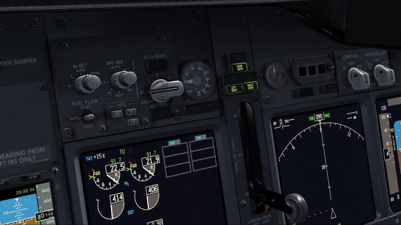
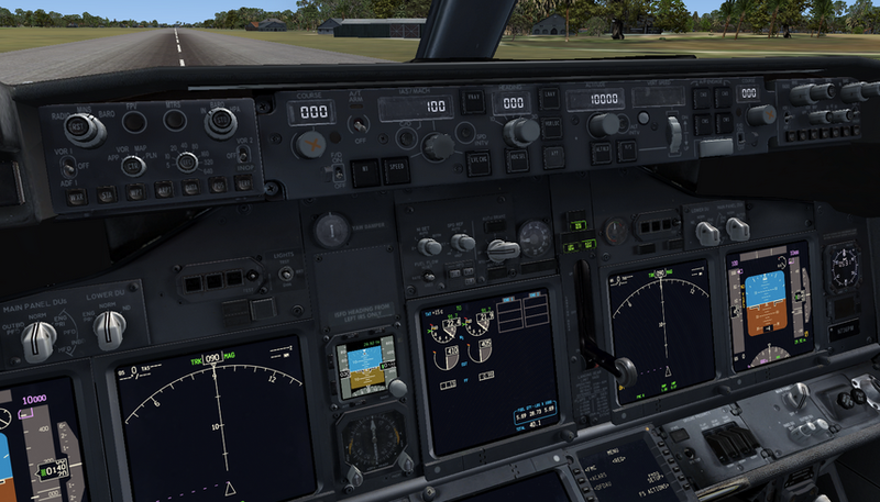
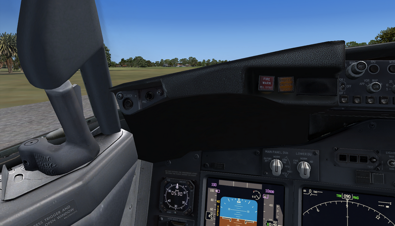
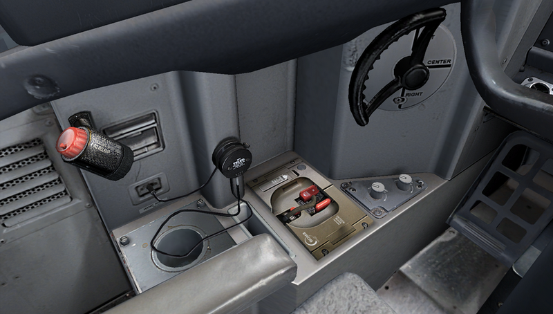
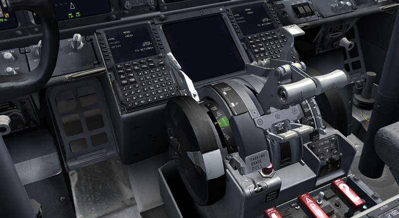
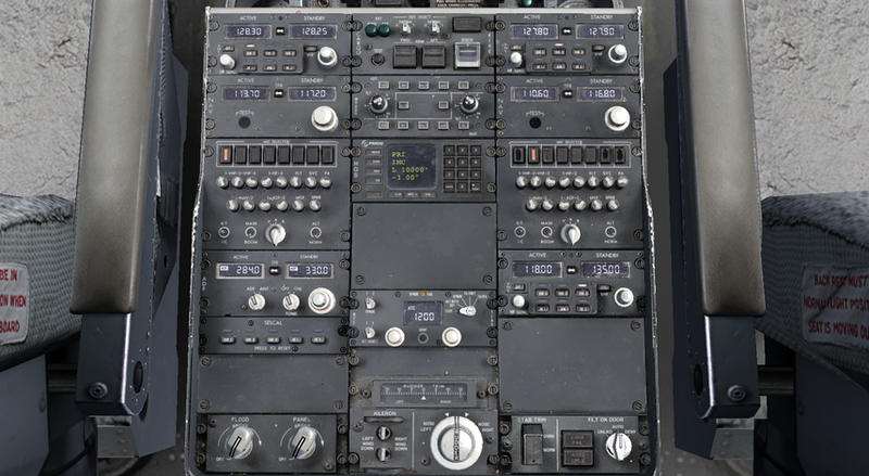
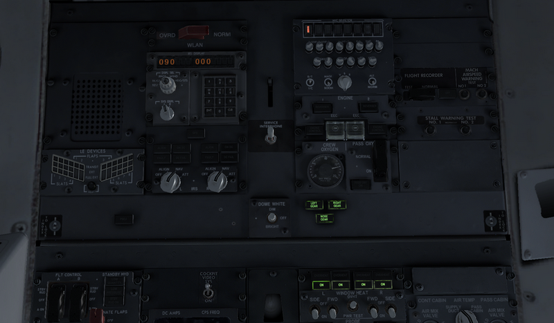
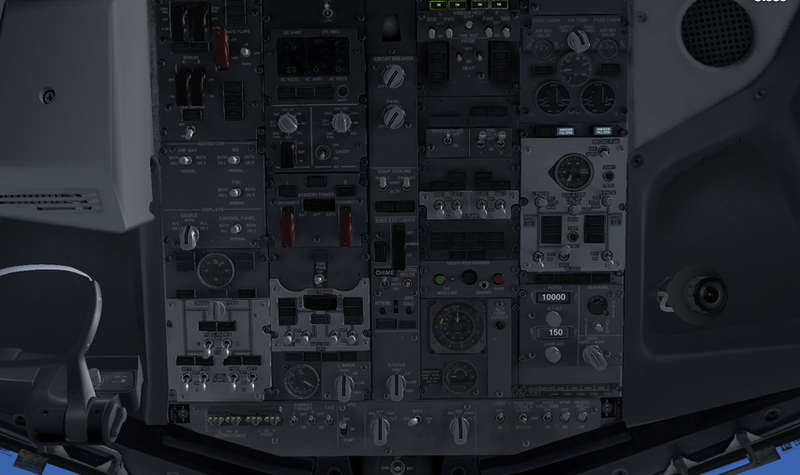
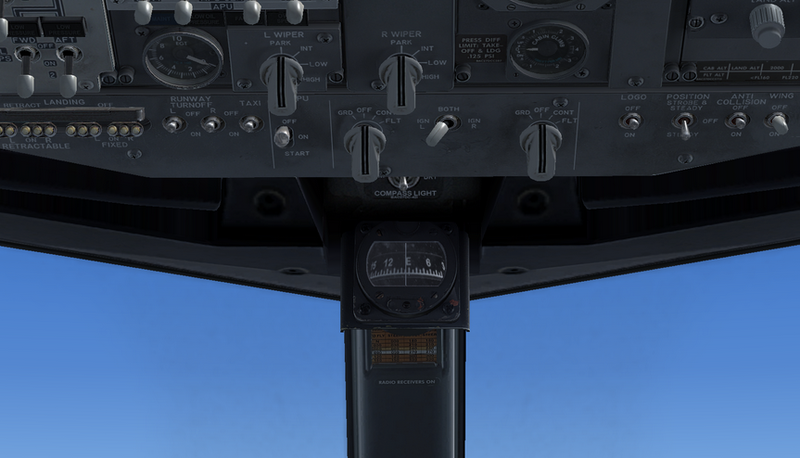
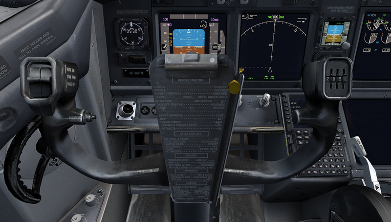
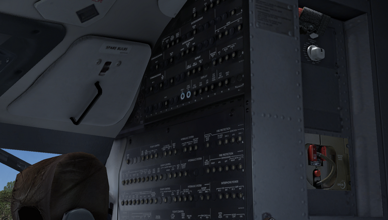
 WIPER MOTOR WIRING


 The Re1 relay is therefore connected which maintains the windshield wiper in operation because its work contact is wired in parallel to the control switch. Once C1 is sufficiently discharged, T1 is blocked, which then blocks T2 and T3 and deactivates relay Re1. The type of components is not really critical, even if we indicate specific reference numbers for T3, any low-power npn transistor with a gain over 25 will work. However, considering the amount of power consumed by the windshield wiper motor, relay Re1 will imperatively be an ‘automobile’ relay.
 .")

.")


 1 - Earth


 Keep the cowl area free of debris


.")

.")


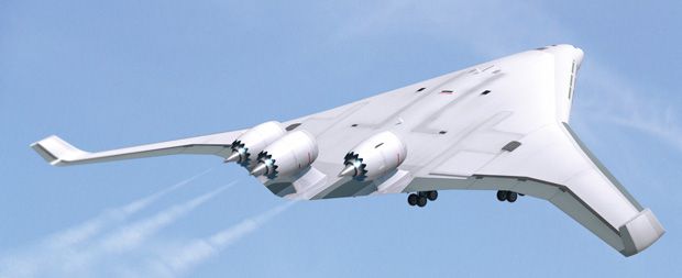
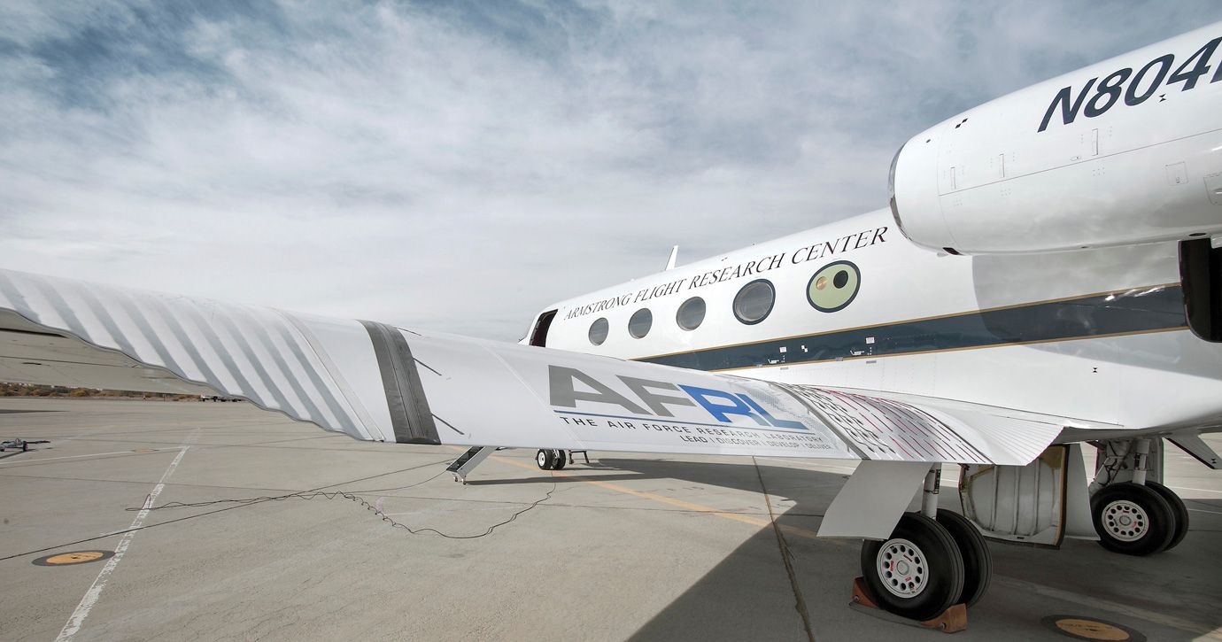
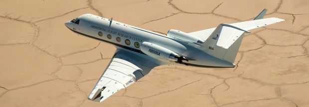
 1/6
1/6
 2/6
2/6
 3/6
3/6
 4/6
4/6
 5/6
To start, I spent the first check from Wright-Patterson to design and rapidly prototype (using what is now called 3D printing) a plastic model of my wing and rent a wind tunnel at the University of Michigan, where I am a professor of mechanical engineering, to conduct a few basic tests. My design performed well in the wind tunnel and appeared scalable, so in 2001 the Air Force awarded me another contract and more money to build a larger prototype that could be tested at higher wind speeds.
5/6
To start, I spent the first check from Wright-Patterson to design and rapidly prototype (using what is now called 3D printing) a plastic model of my wing and rent a wind tunnel at the University of Michigan, where I am a professor of mechanical engineering, to conduct a few basic tests. My design performed well in the wind tunnel and appeared scalable, so in 2001 the Air Force awarded me another contract and more money to build a larger prototype that could be tested at higher wind speeds.
Tidak ada komentar:
Posting Komentar