MARIA PREFER makes energy savings and energy switching with modern inverters AMNIMARJESLOW GOVERNMENT 91320470017 Enerugī kōritsu no takai dengen to shite no inbātā 02096010014 LJBUS__22 ciecle 00 ___ Thanks to Lord Jesus about : God who is a Father in heaven always gives strength to those who are tired and adds to the spirit of the helpless .as like as inverter as an energy-efficient supply ____ Gen.Mac Tech Zone MARIA PEFER for inverters as an energy-saving supply for robotic .
inverter circuits may look simple with their designs, but are able to
produce a reasonably high power output and an efficiency of around 75%.
Learn how to build this cheap mini inverter and power small 220V or 120V appliances such drill machines, LED lamps, CFL lamps, hair dryer, mobile chargers, etc through a 12V 7 Ah battery.
What is a Simple Inverter
An inverter which uses minimum
number of components for converting a 12 V DC to 230 V AC is called a
simple inverter. A 12 V lead acid battery is the most standard form of
battery which is used for operating such inverters. Let's begin with the most simplest in the list which utilizes a couple of 2N3055 transistors and some resistors.
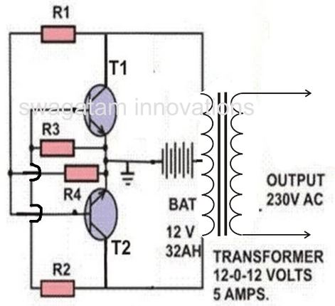
1) Simple Inverter Circuit using Cross Coupled Transistors
The article deals with the construction details
of a mini inverter. Read to know regrading the construction procedure
of a basic inverter which can provide reasonably good power output and
yet is very affordable and sleek. There may be a huge number of
inverter circuits available over the internet and electronic magazines.
But these circuits are often very complicated and hi-end type of
inverters. Thus we are left with no choice but just to wonder how
to build power inverters that can be not only easy to build but also low
cost and highly efficient in its working.
12v to 230v inverter circuit diagram
Well
your search for such a circuit ends here. The circuit of an inverter
described here is perhaps the smallest as far its component count goes
yet is powerful enough to fulfill most of your requirements.
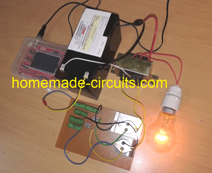
Complete Wiring Layout
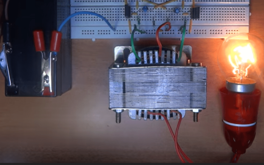
After
the above wiring is completed, it's time to hook it up with a 12V 7Ah
battery, with a 60 watt lamp attached at the transformer secondary. When
switched ON the result would be an instant illumination of the load
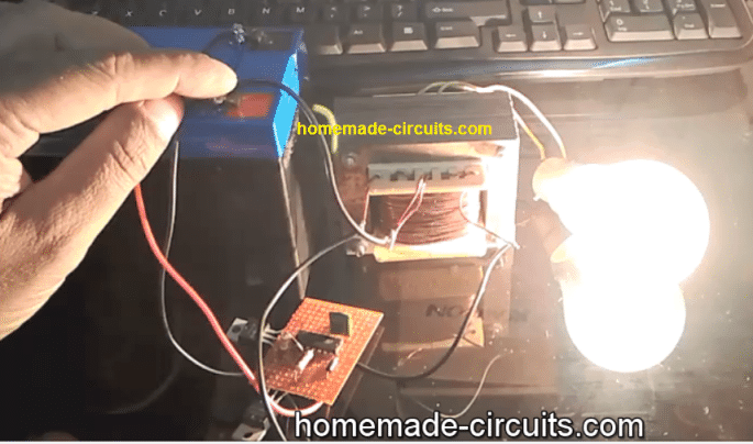
with an astonishing brightness. the key element is the transformer, make sure the transformer is
genuinely rated at 5 amp, otherwise you may find the output power a lot
lesser than the expectation. I can tell this from my experience, I
built this unit twice, once when I was in college, and the second time
recently in the year 2015. Although I was more experienced during the
recent venture I could not get the awesome power that I had acquired
from my previous unit. The reason was simple, the previous transformer
was a robust custom built 9-0-9V 5 amp transformer, compared to the new
one in which I had used probably a falsely rated 5 amp, which was
actually only 3 amp with its output.
Parts List
You will require just the following few components for the construction:
VENTILATED METAL CABINET= AS PER THE SIZE OF THE WHOLE ASSEMBLY
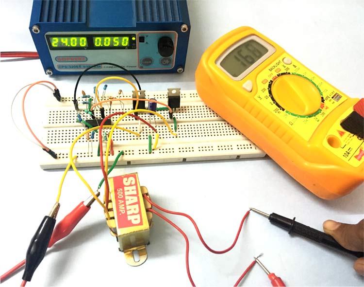
How to Test it?
The testing of this mini inverter is done in the following method:
For testing purpose connect a 60 watt incandescent bulb to the output socket of the inverter.
Next, connect a fully charged 12 V automobile battery to its supply terminals.
The 60 watt bulb should immediately light up brightly, indicating that the inverter is functioning properly.
This concludes the construction and the testing of the inverter circuit.
I
hope from the above discussions you must have clearly understood how to
build an inverter which is not only simple to construct but also very
affordable to each of you.
It can be used to power small
electrical appliances like soldering iron, CFL lights, small portable
fans etc. The output power will lie in the vicinity of 70 watts and is
load dependent.
The efficiency of this inverter is around 75%.
The unit may be connected to your vehicles battery itself when outdoors
so that the trouble of carrying an extra battery is eliminated.
Circuit Operation
The
functioning of this mini inverter circuit is rather unique and
different from the normal inverters which involve discrete oscillator
stage for powering the transistors. However here the two sections
or the two arms of the circuit operate in a regenerative manner. Its
very simple and may be understood through the following points: The
two halves of the circuit no matter how much they are matched will
always consist a slight imbalance in the parameters surrounding them,
like the resistors, Hfe, transformer winding turns etc. Due to this, both the halves are not able to conduct together at one instant. Assume
that the upper half transistors conduct first, obviously they will be
getting their biasing voltage through the lower half winding of the
transformer via R2. However the moment they saturate and conduct fully, the entire battery voltage is pulled through their collectors to the ground. This sucks-out dry any voltage through R2 to their base and they immediately stop conducting. This gives an opportunity for the lower transistors to conduct and the cycle repeats. The whole circuit thus starts to oscillate. The
base Emitter resistors are used to fix a particular threshold for their
conduction to break, they help to fix a base biasing reference level.
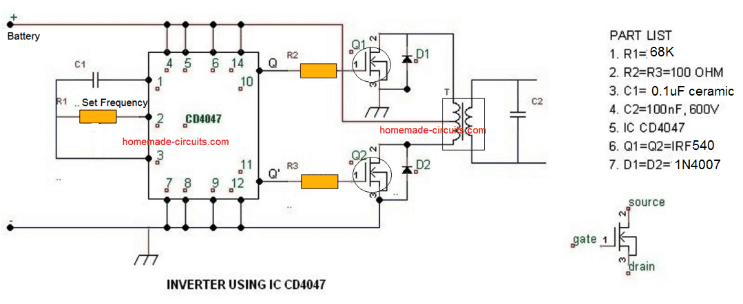
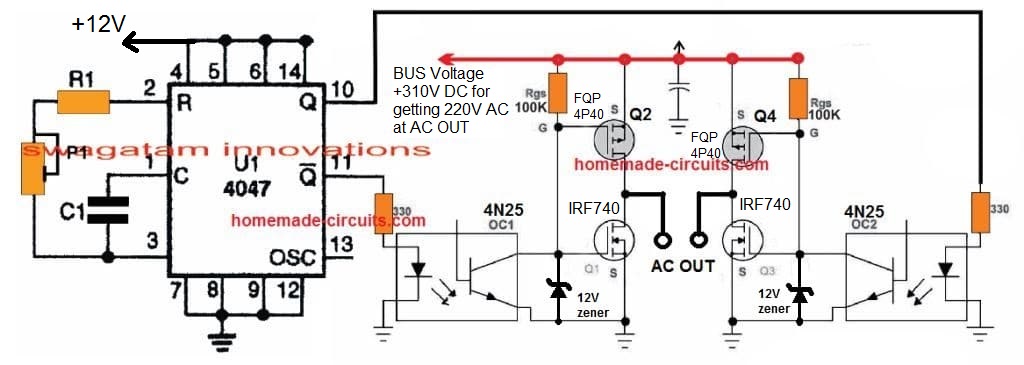
2) Using IC 4047
As shown above a simple yet useful little inverter can be built using just a single IC 4047.
The IC 4047 is a versatile single IC oscillator, which will produce
precise ON/OFF periods across its output pin#10 and pin#11. The
frequency here could be determined by accurately calculating the
resistor R1 and capacitor C1. These components determine the oscillation
frequency at the output of the IC which in turn sets the output 220V AC
frequency of this inverter circuit. It may set at 50Hz or 60Hz as per
individual preference. The battery, mosfet and the transformer can
be modified or upgraded as per the required output power specification
of the inverter. For calculating the RC values, and the output frequency please refer to the datasheet of the IC
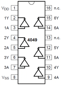
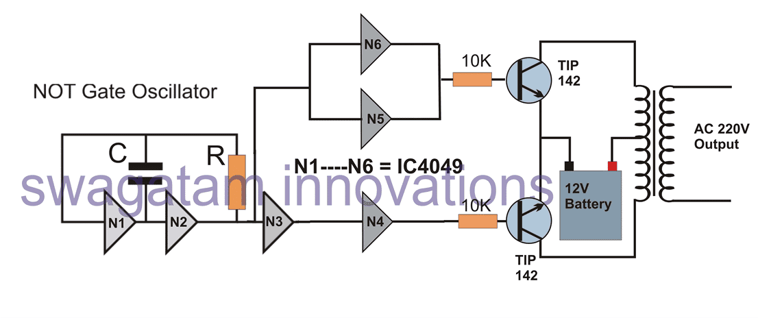
3) Using IC 4049
IC 4049 pin detailsIn this simple inverter circuit we use a single IC 4049 which includes 6 NOT gates or 6 inverters inside.
In the diagram above N1----N6 signify the 6 gates which are configured
as oscillator and buffer stages. The NOT gates N1 and N2 are basically
used for the oscillator stage, the C and R can be selected and fixed for
determining the 50Hz or 60 Hz frequency as per country specs The
remaining gates N3 to N6 are adjusted and configured as buffers and
inverters so that the ultimate output results in producing alternating
switching pulses for the power transistors. The configuration also
ensures that no gates are left unused and idle, which may otherwise
require their inputs to be terminated separately across a supply line. The transformer and battery may be selected as per the power requirement or the load wattage specifications. The output will be purely a square wave output. Formula for calculating frequency is given as: f = 1 /1.2RC, where R will be in Ohms and F in Farads
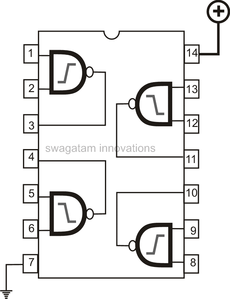
4) Using IC 4093
IC 4093 pin details
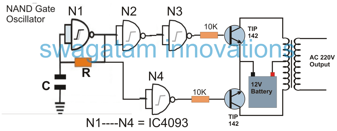
Quite
similar to the previous NOT gate inveter, the NAND gate based simple
inverter shown above can be built using a single 4093 IC. The gates N1
to N4 signify the 4 gates inside the IC 4093. N1,
is wired as an oscillator circuit, for generating the required 50 or
60Hz pulses. These are appropriately inverted and buffered using the
remaining gates N2, N3, N4 in order to finally deliver the alternately
switching frequency across the bases of the power BJTs, which in turn
switch the power transformer at the supplied rate for generating the
required 220V or 120V AC at the output. Although any NAND gate IC
would work here, using the IC 4093 is recommended since it features
Schmidt trigger facility, which ensures a slight lag in switching and
helps creating a kind of dead-time across the switching outputs, making
sure that the power devices are never switched ON together even for a
fraction of a second.
5) Another Simple NAND gate Inverter using MOSFETs
Another
simple yet powerful inverter circuit design is explained in the
following paragraphs which can be built by any electronic enthusiast and
used for powering most of the household electrical appliances
(resistive and SMPS loads). The use of a couple of mosfets
influences a powerful response from the circuit involving very few
components, however the square wave configuration does limit the unit
from quite a few useful applications.
Introduction
Calculating
MOSFET parameters may seem to involve a few difficult steps, however by
following the standard design enforcing these wonderful devices into
action is definitely easy. When we talk about inverter circuits
involving power outputs, MOSFETs imperatively become a part of the
design and also the main component of the configuration, especially at
the driving output ends of the circuit. Inverter circuits being
the favorites with these devices, we would be discussing one such design
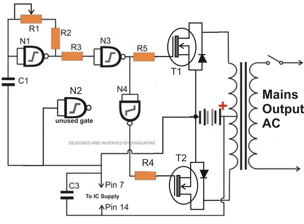
incorporating MOSFETs for powering the output stage of the circuit. Referring
to the diagram, we see a very basic inverter design involving a square
wave oscillator stage, a buffer stage and the power output stage. The
use of a single IC for generating the required square waves and for
buffering the pulses particularly makes the design easy to make,
especially for the new electronic enthusiast.
Using IC 4093 NAND Gates for the Oscillator Circuit
The
IC 4093 is a quad NAND gate Schmidt Trigger IC, a single NAND is wired
up as an astable multivibrator for generating the base square pulses.
The value of the resistor or the capacitor may be adjusted for acquiring
either a 50 Hz or 60 Hz pulses. For 220 V applications 50 Hz option
needs to be selected and a 60 Hz for the 120 V versions. The output from the above oscillator stage is tied with a couple of more NAND gates used as buffers, whose outputs are ultimately terminated with the gate of the respective MOSFETs. The
two NAND gates are connected in series such that the two mosfets
receive opposite logic levels alternately from the oscillator stage and
switch the MOSFETs alternately for making the desired inductions in the
input winding of the transformer.
Mosfet Switching
The
above switching of the MOSFETs stuffs the entire battery current inside
the relevant windings of the transformer, inducing an instant stepping
up of the power at the opposite winding of the transformer where the
output to the load is ultimately derived. The MOSFETs are capable
of handling more than 25 Amps of current and the range is pretty huge
and therefore becomes suitable driving transformers of different power
specs. It’s just a matter of modifying the transformer and the
battery for making inverters of different ranges with different power
outputs.
Parts List for the above explained 150 watt inverter circuit diagram:
R1 = 220K pot, needs to be set for acquiring the desired frequency output.
R2, R3, R4, R5 = 1K,
T1, T2 = IRF540
N1—N4 = IC 4093
C1 = 0.01uF,
C3 = 0.1uF
TR1 = 0-12V input winding, current = 15 Amp, output voltage as per the required specs Formula for calculating frequency will be identical to the one described above for IC 4049. f = 1 /1.2RC. where R = R1 set value, and C = C1
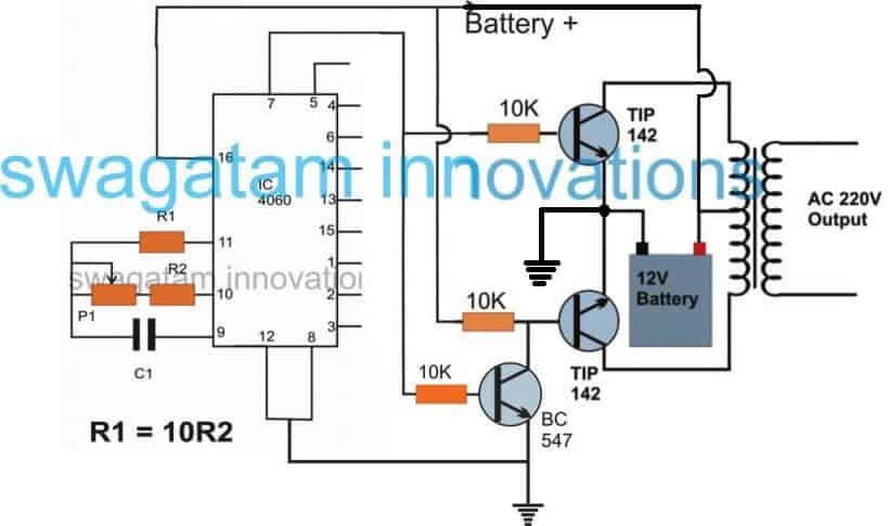
6) Using IC 4060
If
you have a single 4060 IC in your electronic junk box, along with a
transformer and a few power transistors, you are probably all set to
create your simple power inverter circuit using these components. The
basic design of the proposed IC 4060 based inverter circuit can be
visualized in the above diagram. The concept is basically the same, we
use the IC 4060 as an oscillator, and set its output to create alternately switching ON OFF pulses through an inverter BC547 transistors stage. Just
like IC 4047, the IC 4060 requires an external RC components for
setting up its output frequency, however, the output from the IC 4060
are terminated into 10 individual pinouts in a specific order wherein
the output generate frequency at a rate twice that of its preceding
pinout. Although you may find 10 separate outputs with a rate of
2X frequency rate across the IC output pinouts, we have selected the
pin#7 since it delivers the fastest frequency rate among the rest and
therefore may fulfil this using standard components for the RC network,
which may be easily available to you no matter in which part of the
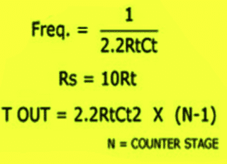
globe you are situated in. For calculating the RC values for R2 +P1 and C1 and the frequency you can use the formula as described below:
Or another way is through the following formula: f(osc) = 1 / 2.3 x Rt x Ct Rt is in Ohms, Ct in Farads More info can be obtained from this article Here's
yet another cool DIY inverter idea which is extremely reliable and uses
ordinary parts for accomplishing a high power inverter design, and can
be upgraded to any desired power level. Let's learn more about this simple design
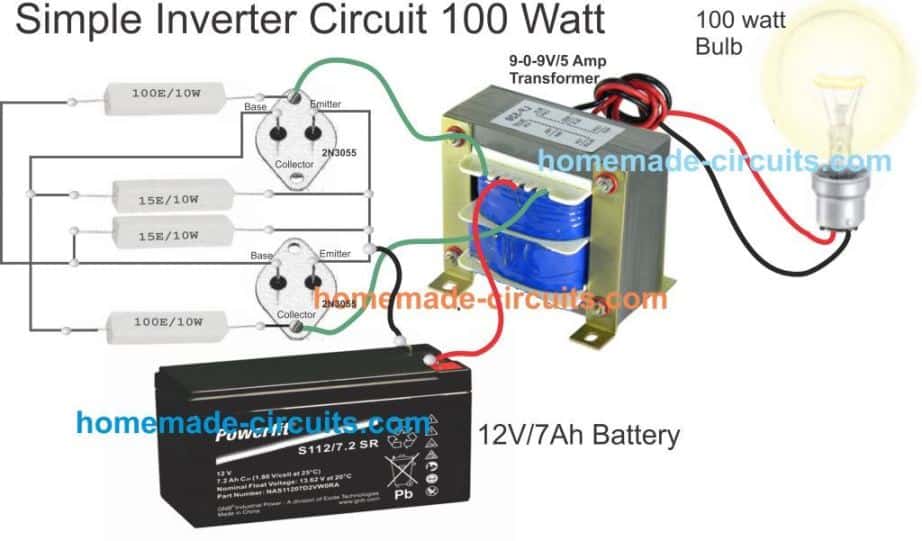
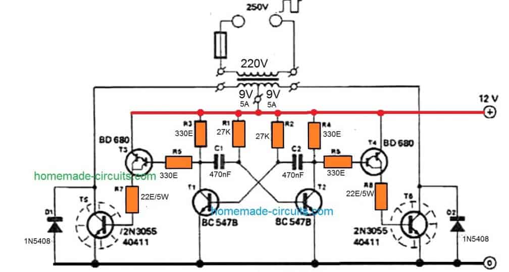
7) Simplest 100 Watt Inverter for the Newcomers
The
circuit of a simple 100 watt inverter discussed in this article can be
considered as the most efficient, reliable, easy to build and powerful
inverter design. It will convert any 12V to 220V effectively using
minimum components The proposed simple 100 watt inverter circuit disign was published
quite a long time ago in one of the elektor electronics magazines and
according to me this circuit is one of the best inverter designs you can
get.
I
consider it to be the best because the design is well balanced, well
calculated, utilizes ordinary parts and if done everything correctly
would start working instantly. The efficiency of this design is in the vicinity of 85% that's good considering the simple format and low costs involved.
Using an Transistor Astable as the 50Hz Oscillator
Basically
the whole design is built around an astable multivibrator stage,
consisting of two low power general purpose transistors BC547 along with
the associated parts consisting of two electrolytic capacitors and some
resistors. This stage is responsible for generating the basic 50 Hz pulses required for initiating the inverter operations. The
above signals are at low current levels and therefore requires to be
lifted to some higher orders. This is done by the driver transistors
BD680, which are Darlington by nature. These transistors receive
the low power 50 Hz signals from the BC547 transistor stages and lift
them at higher current levels so that it can be fed to the output
transistors. The output transistors are a pair of 2N3055 which receive an amplified current drive at their bases from the above driver stage.
2N3055 Transistors as the Power Stage
The
2N3055 transistors thus are also driven at high saturation and high
current levels which gets pumped into the relevant transformer windings
alternately, and converted into the required 220V AC volts at the
secondary of the transformer.
Parts List for the above explained simple 100 watt inverter circuit
R1,R2 = 27K, 1/4 watt 5%
R3,R4,R5,R6 = 330 OHMS, 1/4 watt 5%
R7,R8 = 22 OHMS, 5 WATT WIRE WOUND TYPE
C1,C2 = 470nF
T1,T2 = BC547,
T3,T4 = BD680, OR TIP127
T5,T6 = 2N3055,
D1,D2 = 1N5402
TRANSFORMER = 9-0-9V, 5 AMP
BATTERY = 12V,26AH,
Heatsink for the T3/T4, and T5/T6
Specifications:
Power Output: 100 watts if single 2n3055 transistors are used on each channels.
Frequency: 50 Hz, Square Wave,
Input Voltage: 12V @ 5 Amps for 100 Watts,
Output Volts: 220V or 120V(with some adjustments)
From
the above discussion you might be feeling thoroughly enlightened
regarding how to build these 7 simple inverter circuits, by configuring a
given basic oscillator circuit with a BJT stage and a transformer, and
by incorporating very ordinary parts which may be already existing with
you or accessible by salvaging an old assembled PC board.
How to Calculate the Resistors and Capacitors for 50 Hz or 60 Hz Frequencies
In this transistor based inverter circuit, the oscillator design is built using a transistorized astable circuit. Basically
the resistors and capacitors associated with the bases of the
transistors determine the frequency of the output. Although these are
correctly calculated to produce approximately 50 Hz frequency, if you
are further interested to tweak the output frequency as per own
preference you can easily do so by calculating them through this Transistor Astable Multivibrator Calculator. __________________________________________________________________________________
SOLAR INVERTER
Typically, grid connected inverters have a life span ranging from 10 to 20 years. You should expect most to last 10 years minimum. Solar inverters
have warranties ranging from 5 to 12 years with an increasing number of
manufacturers offering pay for service warranty extension .
When your solar panels collect sunlight and turn it into energy, it gets sent to the inverter, which takes the DC energy and turns it into AC energy. At that point, your solar electricity can power your appliances and electronics or, if you're producing more electricity than you need, it can feed back into the grid. Most inverters will derate at around 45 – 50 Degrees C. In the inhabited places of Planet Earth, temperature will rarely climb above 45 degrees C (113 Degrees F). So, simply putting the inverter in a shaded area with good airflow will almost always result in an inverter that doesn't derate.
top 5 Solar inverters - Residential
Fronius. Fronius Inverters have surged in popularity since the release of the snap-in design around 4 years ago. ...
SolarEdge. The compact SolarEdge HD wave solar inverter. ...
SMA. SMA Sunny Boy AV solar inverter. ...
Sungrow. ...
Solax Power.
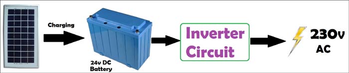
We have limited natural resources and that too we are using in
generating Electricity. That’s why there is lot of emphasis is given on
generating and using clean energy. Today in this project, we will see
how electricity can be generated from the sunlight, how it can be stored
in the form of DC, and then how it is converted into AC to drive home
appliances.
In a solar power plant, solar energy is converted
into electrical energy by using photovoltaic solar panels and then
generated DC (Direct Current) is stored in batteries which is further
converted by into Alternating Current (AC) by solar inverters. Then this
AC is fed into commercial electrical grid or can be directly supplied
to the consumer. In this tutorial, we will show how to make a Small Solar Inverter Circuit for Home Appliances.
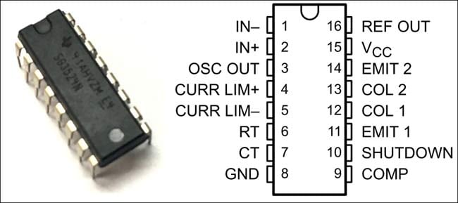
Here SG3524 chip is the primary
component to build a Solar Inverter. It has complete circuitry for Pulse
Width Modulator (PWM) control. It also has all the functions to
construct a Regulated Power Supply. SG3524 chip offers improved performance and requires less external parts while building switching power supplies.
SG3524 - Regulating Pulse-Width Modulators
SG3524 incorporates all the necessary functions to
design a switching regulator and inverter. This IC can also be used as a
control element for high-power applications.
Some of the application of SG3524 IC are:
Transformer-coupled DC-DC converters
Voltage doublers without using transformer
Polarity-converter applications
Pulse-width modulation (PWM) techniques
This single IC consists of on-chip regulator,
programmable oscillator, error amplifier, pulse-steering flip-flop, two
uncommitted pass transistors, a high-gain comparator, and
current-limiting & shut-down circuitry.
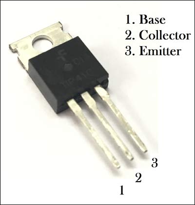
TIP41 High Power NPN Transistor
TIP41 is a general purpose NPN Power transistor
with high switching speed and improved Gain, mainly used for medium
power Linear Switching Applications. Due to high rating of VCE, VCB and VEB
which is 40V, 40V and 5V respectively, we have used this transistor for
inverter circuit. Also, it has a maximum collector current of 6A.
Here, in this circuit these transistors are used for driving the 12-0-12 Step-up transformer.
Material Required
SG3254 IC
Solar Panel
TIP41 High Power NPN Transistor
Resistors (4 ohm,100k, 1k, 4.7k, 10k, 100k)
Capacitors (100uf, 0.1uf, 0.001uf)
12-0-12 Step-Up-transformer
Connecting Wires
Breadboard
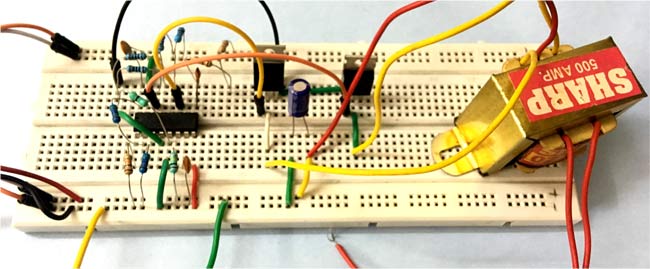
Circuit Diagram
Working of Solar Inverter Circuit
Initially, the solar panel is charging the
rechargeable battery and then the battery is supplying voltage to the
inverter circuit. To know more about charging a battery using solar
panel follow this circuit. Here, we are using RPS instead of rechargeable battery.
The circuit consists of IC SG3524 which operates at a fixed frequency, and this frequency is determined by 6th and 7th
pin of the IC which is RT and CT. RT set up a charging current for CT,
so a linear ramp voltage exists at CT, which is further fed to the
inbuilt comparator.
For providing reference voltage to the circuit SG3524 have an inbuilt 5V regulator. A voltage divider network
is created by using two 4.7k ohm resistors which feeds the reference
voltage to the inbuilt error amplifier. Then the amplified output
voltage of error amplifier is compared with the linear voltage ramp at
CT by the comparator, hence producing a PWM (Pulse Width Modulation)
pulse.
This PWM is further fed to the output pass
transistors through the pulse steering flip flop. This pulse steering
flip flop is synchronously switched by the inbuilt oscillator output.
This oscillator pulse also acts as a blanking pulse to ensure that both
the transistors are never turned ON simultaneously during the transition
times. The value of CT controls the duration of the blanking pulse.
Now, as you can see in the circuit diagram pin 11
and 14 are connected to the TIP41 transistors for driving the step up
transformer. When output signal at pin 14 is HIGH, transistor T1 turns
ON and current flows from the source to the ground via the upper half of
the transformer. And, when output signal at pin 11 is HIGH, transistor
T2 turns ON and current flows from the source to the ground via the
lower half of the transformer. Therefore, we receive Alternating Current
at the output terminal of the step up transformer.
** In some cases, problem inverters only need a reboot and are not broken at all. In other cases, we may recommend inverter repair or a complete inverter replacement. Every day you spend with a faulty panel or inverter costs you money.
** Four AWG battery cables should be used on power inverters rated up to 1500 watts and most commonly used on 900, 1000, 1100, 1200 watt inverters. _________________________________________________________________________________
Working of Solar Inverter, Its Advantages and Disadvantages
Solar Inverter Currently, the necessity
of the solar inverter has been improving day by day. It is a common
inverter, but uses energy from the sun that is termed as “solar
energy”. This kind of inverter helps in changing the DC-AC uses solar
power. In this circuit, the DC power flows in one direction and also
assists in supplying current when there is no electricity.DC is used for
minor appliances like electronic gadgets, MP3 players, iPod, etc
(where there is power stored in the battery). In the case of
alternative current (AC) is the power that stores back and forth
inside the circuit. Usually, the AC power is used for home appliances. A
solar inverter aids several devices that work on DC power to run on
AC power so that the worker makes use of the AC power. If you are
thinking this inverter is as an alternate to the normal electric
one, then it is due to the solar inverter that makes use of the solar
energy which is available in sufficient from the Sun and is spotless
and also pollution free.
What is a Solar Inverter?
The Solar Inverter is an important device in any solar based power system.
The basic function of this inverter is to alter the flexible DC o/p
of the solar panels into AC. The various electrical and electronic
components are used to make the circuit to help in the conversion.
The changed AC power is used for running
your home appliances. For some specific applications, we can directly
use the DC power from the solar panel like a cell phone charger. LED
night lights. Normally, the power of a home solar power system is used
for power AC loads.
Solar Inverter Project
The main scope of the project is, the
photovoltaic cells are converting the sunlight into electricity a charge
controller is used. PV cells are bundled together in modules or panels
to produce higher voltages and increased power. As the sunlight varies
in intensity the electricity, so generated. Usually charges through the charge a set of batteries for storing the energy.
Hardware Requirements
Battery
PWM
inverter
MOSFET
Photovoltaic cells/solar cells
Resistor
Capacitor
Solar Inverter Block Diagram by Edgefxkits.com
Battery
An electrical battery is a combination
of one or more electrochemical cells, used to convert stored chemical
energy into electrical energy. The battery has become a common power
source for many household, robotics and industrial applications.Larger
batteries provide standby power for telephone exchanges or computer data
centers.
Battery
PWM Inverter IC
The PWM Inverter is used to develop the
PWM pulses based on a fixed frequency using a common oscillator The IC
SG3524 operates at a fixed frequency, the oscillation frequency is
determined by one timing resistor RT and one timing capacitor CT.The
SG3524 contains an inbuilt 5V regulator that supplies as a reference
voltage, also providing the SG3524 internal regulator control circuitry.
Comparator provides a linear control of the output pulse width
(duration) by the error amplifier.The resultant PWM pulse from the
comparator is passed to the corresponding output pass transistor (Q1, Q2
refers block diagram) using the pulse steering flip flop, which is
synchronously toggled by the oscillator output.
PWM Inverter IC
MOSFET(IRF 510)
The metal–oxide–semiconductor
field-effect transistor (MOSFET, MOS-FET, or MOS FET) is a device used
for amplifying or switching electronic signalsThe basic principle of the
device a voltage on the oxide-insulated gate electrode can induce a
conducting channel between the two other contacts called the source and
drainIt is by far the most common transistor in both digital and analog
circuits, though the bipolar junction transistor was at one time much
more common.
MOSFET (IRF 510)
BC547 (NPN –Transistor)
The BC547 transistor is an NPN Epitaxial
Silicon Transistor.It is used in general-purpose switching and
amplification BC847/BC547 series 45 V, 100 mA NPN general-purpose
transistors.The ratio of two currents (Ic/Ib) is called the DC Current
Gain of the device and is given the symbol of hfe or nowadays Beta,
(β). The current gain from the emitter to the collector terminal, Ic/Ie,
is called Alpha, (α), and is a function of the transistor itself.
1N4148
The 1N4148 is a standard small signal
silicon diode used in signal processing. The 1N4148 is generally
available in a DO-35 glass package and is very useful at high
frequencies with a reverse recovery time of no more than 4ns. This
permits rectification and detection of radio frequency signals very
effectively, as long as their amplitude is above the forward conduction
threshold of silicon (around 0.7V) or the diode is biased.
1N4148
Photovoltaic Cells
Photovoltaic (PV) cells are made of
special materials called semiconductors such as silicon, which is
currently the most commonly used. Basically, when light strikes the
cell, a certain portion of it is absorbed within the semiconductor
material. PV cells also all have one or more electric fields that act to
force electrons freed by light absorption to flow in a certain
direction. This flow of electrons is a current, and by placing metal
contacts on the top and bottom of the PV cell, we can draw that current
off to use externally.
Solar Panel
Expose the cell to light, and the energy
of each photon (light particle) hitting the silicon, will liberate an
electron and a corresponding hole. If this happens within range of the
electric field’s influence, the electrons will be sent to the N side and
the holes to the P one, resulting in yet further disruption of
electrical neutralityThis flow of electrons is a current; the electrical
field in the cell causes a voltage and the product of these two is
power.
Solar Panel
Solar Inverter Project Working
The main concept of this project is to design a solar energy based inverter
for household applications. The hardware requirements of this project
include Step up Transformer, Bridge-MOSFETs drive, Solar Panel, MOSFET
driver, Voltage regulator, PWM inverter IC, and Battery. Sun powered
vitality is changed to electrical vitality with the assistance of
photovoltaic cells. This vitality is put away in batteries amid daytime
for the operation reason at whatever point required. The proposed
framework is intended to use sunlight based vitality for home burdens
utilizing an inverter.
A sun oriented inverter changes over the
DC (Direct Current) o/p of a PV sunlight based board into a utility
frequency AC (alternating current) that can be sustained into a business
electrical network (or) utilized by a local, off-line electrical n/w.
In this project, the sun oriented
vitality is stored in the battery from PV cells. This vitality of the
battery changes to AC supply of 50Hz frequency utilizing PWM inverter IC
with MOSFET to the driver MOSFET connects and step up the voltage by a
transformer, all in an off-line n/w only just however not lattice tie
sort.
For test purposes a battery of the SMF
sort of and 5 AH (not provided, it is for the most part utilized as a
part of little UPS) is important to be utilized as sun oriented cells
required would be of the high power sort throwing high. Additionally,
this system can be added to a charge controller for over voltage, under
voltage protection and over-burden security.
Advantages of Solar Inverter
After discussing in detail about a solar
inverter and how it is a fit for making appliance work at housing &
trade levels we must discuss about the numerous advantages of the solar
inverter.
Solar energy has continually helped in diminishing the greenhouse impact and an unnatural weather change.
By utilizing of sun based gadgets will
help in sparing cash and furthermore vitality. Since many individuals
have begun utilizing these gadgets.
A sun powered inverter helps in
changing the DC into batteries or AC. This backings individuals who
utilize an incomplete measure of power.
The synchronous solar inverter that
enables small homeowners and furthermore to control organizations as
they are tremendous in measure.
The multifunction sunlight based
inverter is the finest among all and works effected. It changes over the
DC to AC deliberately which is appropriate for business foundations.
This inverter is financially effective,
i.e. ease than generators. Apart from these, there are extra gadgets as
well that make the utilization of sunlight based vitality, for example,
solar heater, cooker.
Disadvantages of Solar Inverter
Primarily, we have to spend a considerable measure of cash for buying a solar based inverter
It will work productively and create DC
just when the sunshine is solid. The solar panels are utilized to draw
in the daylight needs lots of space.
Solar Inverters can work when there is
no Sunshine yet the battery which is accessible in that is charged
completely with the assistance of Sunshine.
What is the future of service robots?
Standardisation defines a service robot as, “a robot that performs
useful tasks for humans or equipment, excluding industrial automation
applications”. It’s predicted that these types of robots will play a
greater role in the maintenance, security and rescue markets, but
interestingly, the latest sector to embrace automation and robotics is
tourism. Italy’s first robot concierge, Robby Pepper, has been
employed to answer the frequent questions from the guests at a popular
hotel resort. Programmed to understand and respond in Italian, English
and German, Robby has been taught the locations of spas, restaurants and
opening times to relieve overwhelmed staff during the summer tourist
season. This is just one example of how the rise of artificial
intelligence (AI) and robotics is being utilised to improve the services
offered across sectors. Specialist robots like Robby are often
required to be autonomous and free from an alternating current (AC)
supply. Original equipment manufacturers (OEMs) therefore integrate
portable batteries into their designs to power service robots. The
problem is that, as manufacturers create more intuitive robots, the
power demands for these devices become significantly greater and often
beyond the capability of many existing power sources. At
Ultralife, we understand that being able to reliably power a robotic
system is important to avoid the financial burden of unexpected
downtime, reprogramming and maintenance. This is why we created the
range of primary, non-rechargeable, Lithium Thionyl Chloride and Lithium
Manganese Dioxide cells and batteries. These batteries can be
integrated by OEMs and design engineers as backup batteries into service
robot applications to ensure safe operation. Users also have the added
benefit of the batteries featuring Ultralife’s Smart Circuit
technology. This smart functionality provides users with critical
information including cycle count, remaining run-time and remaining
capacity, for added safety. for example, are programmed to learn and improve their knowledge
while in operation. Depending on the memory storage feature installed in
the device, loss of power could impact the robot’s development. If the
robot uses flash memory settings for example, then any information Robby
stored could be forgotten because of losing power. Unlike
industrial robots, service robots are at work in a wide range of
environments and everyday life applications. Often using more advanced
technology, service robots face distinct power requirements as a result.
So, having a backup power source is essential to help businesses
avoid frequent re-teaching or reprogramming any critical or previously
learned information. With the IFR expecting to see a substantial
increase in the use of service robots across industry, OEMs and design
engineers must consider the power source that’s going to operate their
application. Robby may be the first Italian robot concierge
but, providing every service robot can be reliably powered and reduce
the pressure of medial tasks during busy periods, it is very unlikely he
will be the last.
System integration has been around already for a while. Its lofty goal
is to bring together different systems and get them to work together so
well, they can be regarded as a single system, instead of a collection
of systems.
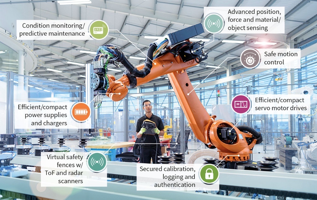
Advance your robots with technology and insight
The robotics sector is booming, creating a wealth of
new opportunities in manufacturing, logistics and beyond. Today’s robots
are able to identify and navigate their surroundings, work alongside
humans and teach themselves the skills required to complete a new task.
Though they are capable of doing more and more, robots are becoming
easier and easier to operate. Outside the boundaries of their
traditional workplace behind a safety fence, these robots are assisting
in and enhancing a host of new and conventional applications. All this wouldn’t be possible without semiconductor solutions.
Whether in an industrial robot, a cobot or an automated guided vehicle
(AGV), intelligent semiconductors are the key enabler for all major
robotic functions, from sensing and motion control to functional safety
to security.
Ready-to-use solutions for the latest robotics trends
No matter the precise robotics application, at Infineon
you’ll find ready-to-use semiconductor solutions that cover all major
robotic trends. This includes power management, motor control, security,
communication, environmental sensing, and position and condition
sensing.
Focus on what really counts
The success of a robotics project often hinges on the
availability and scalability of the semiconductor solutions required. At
our manufacturing sites, we produce flexibly to your specifications
while always upholding the highest quality standards. Collaborate with
us to benefit from our unique capabilities, outstanding robotics
expertise and dedicated application support.


Tidak ada komentar:
Posting Komentar