Different Types of Diodes
Different Types of Diodes
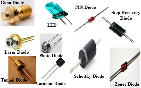
There are several types of diodes are available for use in electronics design, namely; a Backward diode, BARITT diode, Gunn Diode, Laser diode, Light emitting diodes, Photodiode, PIN diode, PN Junction, Schottky diodes, Step recovery diode, Tunnel diode, Varactor diode and a Zener diode.
Backward Diode
This type of diode is also called the back diode, and it is not widely used. The backward diode is a PN-junction diode that is similar to the tunnel diode in its process. It finds a few special applications where its specific properties can be used.
BARITT Diode
The short term of this diode Barrier Injection Transit Time diode is BARITT diode. It is applicable in microwave applications and allows many comparisons to the more widely used IMPATT diode. Please refer the below link for BARRITT Diode
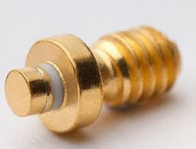
Gunn Diode
Gunn diode is a PN junction diode, this sort of diode is a semiconductor device that has two terminals. Generally, it is used for producing microwave signals.
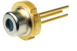
Laser Diode
The laser diode is not the similar as the ordinary LED (light emitting diode) because it generates coherent light. These diodes are extensively used in many applications like DVDs, CD drives and laser light pointers for PPTs. Although these diodes are inexpensive than other types of laser generator, they are much more expensive than LEDs. They also have a partial life.Please refer the below link for: How to Make a Laser Pointer
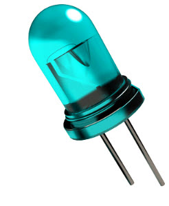
Light Emitting Diode
The term LED stands for light emitting diode, is one of the most standard types of the diode. When the diode is connected in forwarding bias, then the current flows through the junction and generates the light. There are also many new LED developments are changing they are LEDs and OLEDs.Please refer the below link for: LED Light Sources
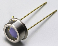
Photodiode
The photodiode is used to detect light. It is found that when light strikes a PN-junction it can create electrons and holes. Typically, photodiodes operate under reverse bias condition where even a small amount of flow of current resulting from the light can be simply noticed. These diodes can also be used to produce electricity.Please refer the below link for Photodiode Working Principle, and Its Characteristics
PIN Diode
This type of diode is characterized by its construction. It has the standard P-type & N-type regions, but the area between the two regions namely intrinsic semiconductor has no doping. The region of the intrinsic semiconductor has the effect of increasing the area of the depletion region which can be beneficial for switching applications.Please refer the below link forPIN Diode Basics, Working, and Its Applications.
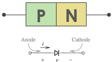
PN Junction Diode
The standard PN junction may be thought of as the normal or standard type of diode in use today. These diodes can come as small signal types for use in RF (radio frequency), or other low current applications which may be called as signal diodes. Other types may be planned for high voltage and high current applications and are normally named rectifier diodes.Please refer the below link for PN Junction Diode Theory and VI Characteristics
Schottky Diode
The Schottky diode has a lower forward voltage drop than ordinary Si PN-junction diodes. At low currents, the voltage drop may be between 0.15 & 0.4 volts as opposed to 0.6 volts for a Si diode. To attain this performance they are designed in a different way to compare with normal diodes having a metal to semiconductor contact. These diodes are extensively used in rectifier application, clamping diodes, and also in RF applications.Please refer the below link for Schottky Diode Working and Applications
Step Recovery Diode
A step recovery diode is a type of microwave diode used to generate pulses at very HF (high frequencies). These diodes depend on the diode which has a very fast turn-off characteristic for their operation.
Tunnel Diode
The tunnel diode is used for microwave applications where its performance surpassed that of other devices of the day.Please refer the below link for Tunnel Diode Circuit with Operation and Its Applications.
Varactor Diode or Varicap Diode
A varactor diode is one sort of semiconductor microwave solid-state device and it is used in where the variable capacitance is chosen which can be accomplished by controlling voltage. These diodes are also called as variceal diodes. Even though the o/p of the variable capacitance can be exhibited by the normal PN-junction diodes.But, this diode is chosen for giving the preferred capacitance changes as they are different types of diodes. These diodes are precisely designed and enhanced such that they allow a high range of changes in capacitance. Please refer the below link for Varactor Diode Working and Its Applications.
Zener Diode
The Zener diode is used to provide a stable reference voltage. As a result, it is used in vast amounts. It works under reverse bias condition and found that when a particular voltage is reached it breaks down. If the flow of current is limited by a resistor, it activates a stable voltage to be generated. This type of diode is widely used to offer a reference voltage in power supplies. Please refer the below link for Zener Diode Circuit Working and Its Applications.
Thus, this is all about different types of diodes and its uses.We hope that you have got a better understanding of this concept or to implement electrical projects please give your valuable suggestions by commenting in the comment section below. Here is a question for you, What is the function of a diode?
Some important diodes and their applications
1. PN Junction diode -
The ordinary diode used in most applications from rectifiers to clippers.

2. Zener diode -
A diode with a high reverse breakdown voltage used as a voltage regulator.

3. Photodiode -
A diode which emits electron hole pairs when exposed to light, used to make detectors and solar cells among other things.

4. Light-Emitting Diode (LED)-
The inverse of the photodiode, it gives out light when driven by electricity. Its low power consumption makes it an attractive lighting source.

5. Tunnel diode -
A diode capable of very high speed operation due to the quantum tunneling effect. It is used in high frequency applications.

6. Varactor diode -
A diode whose capacitance can be varied with applied voltage.

And Finally....
7. Schottky diode -
It is a diode which is used to maintain a fixed voltage of 0.15 - 0.45 Volts. It is used mainly to speed up transistor switching. The Schottky diode has a lower voltage across its terminals when compared to other diodes as it consists of a metal-semiconductor junction as opposed to a P-N junction in others.
It is connected across the base and collector of an npn transistor to maintain a constant voltage (as shown in figure). This prevents the transistor from going into saturation which would slow down switching. These high speed transistors are called Schottky transistors.

The more important point is that the Schottky diode has a lower reverse recovery time compared to the transistor and can switch back faster. Without this feature, the diode would impede the transistor's operation itself. But the Schottky diode enables faster switching as it switches faster than the transistor it is connected to.

1. PN Junction diode -
The ordinary diode used in most applications from rectifiers to clippers.
2. Zener diode -
A diode with a high reverse breakdown voltage used as a voltage regulator.
3. Photodiode -
A diode which emits electron hole pairs when exposed to light, used to make detectors and solar cells among other things.
4. Light-Emitting Diode (LED)-
The inverse of the photodiode, it gives out light when driven by electricity. Its low power consumption makes it an attractive lighting source.
5. Tunnel diode -
A diode capable of very high speed operation due to the quantum tunneling effect. It is used in high frequency applications.
6. Varactor diode -
A diode whose capacitance can be varied with applied voltage.
And Finally....
7. Schottky diode -
It is a diode which is used to maintain a fixed voltage of 0.15 - 0.45 Volts. It is used mainly to speed up transistor switching. The Schottky diode has a lower voltage across its terminals when compared to other diodes as it consists of a metal-semiconductor junction as opposed to a P-N junction in others.
It is connected across the base and collector of an npn transistor to maintain a constant voltage (as shown in figure). This prevents the transistor from going into saturation which would slow down switching. These high speed transistors are called Schottky transistors.
The more important point is that the Schottky diode has a lower reverse recovery time compared to the transistor and can switch back faster. Without this feature, the diode would impede the transistor's operation itself. But the Schottky diode enables faster switching as it switches faster than the transistor it is connected to.
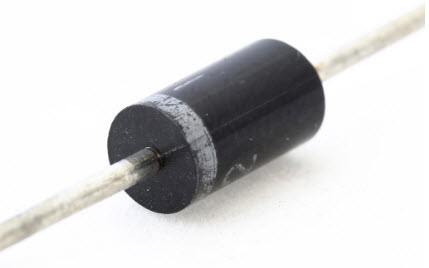
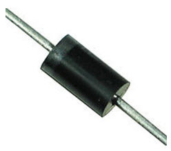
RECTIFIER DIODES
| Model Number | Diode Type | Peak Inverse Voltage | Current |
|---|---|---|---|
| 1N4001 | Rectifier | 50 V | 1 A |
| 1N4002 | Rectifier | 100 V | 1 A |
| 1N4003 | Rectifier | 200 V | 1 A |
| 1N4004 | Rectifier | 400 V | 1 A |
| 1N4005 | Rectifier | 600 V | 1 A |
| 1N4006 | Rectifier | 800 V | 1 A |
| 1N4007 | Rectifier | 1,000 V | 1 A |
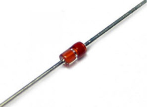
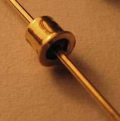
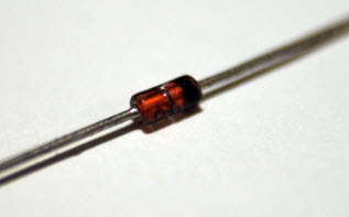
SIGNAL DIODES
- They’re noticeably smaller than rectifier diodes and are often made of glass. You have to look at them closely to see it, but the cathode end of a signal diode is marked by a small black band.
- They’re better than rectifier diodes when dealing with high-frequency signals, so they’re often used in circuits that process audio or radio frequency signals. Because of its ability to respond quickly at high frequencies, signal diodes are sometimes called high-speed diodes. They’re also sometimes called switching diodes because digital circuits often use them as high-speed switches.
- Some signal diodes are made of germanium rather than silicon. (Germanium the crystal, not to be confused with geranium the flower.) Germanium diodes have a much smaller forward-voltage drop than silicon diodes — as low as 0.15 V. This makes them useful for radio applications, which often deal with very weak signals.
ZENER DIODES
XXX . XXX What Are the Functions of a Diode in an Alternator?
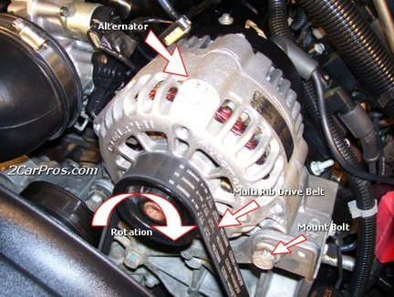
 Rectifier diodes are electronic devices that allow electrical current to flow in one direction only. Because of this electrical property, diodes are used to convert alternating current electrical energy into direct current electrical energy. In an automotive electrical system, diodes can be found in several places, including the alternator. Alternator diodes perform three critical functions for the automotive charging system.
Rectifier diodes are electronic devices that allow electrical current to flow in one direction only. Because of this electrical property, diodes are used to convert alternating current electrical energy into direct current electrical energy. In an automotive electrical system, diodes can be found in several places, including the alternator. Alternator diodes perform three critical functions for the automotive charging system.
Conversion from AC to DC Power
An alternator converts mechanical energy into electrical energy by creating a variable electromagnetic field. This field is induced across alternator windings, and creates an alternating current signal. However, the electrical devices in a car require direct current electrical energy. The electrical energy passes through a device called a rectifier, which is made up of six or more diodes. The rectifier converts the alternating current energy produced by the alternator into direct current energy the automobile can use.
Feedback Preventer
At times, some electrical parts fail. If a part fails suddenly, there is typically a short burst of energy fed back into the electrical system. A fuse typically protects most electrical components from feedback; however, the alternator is not typically protected by a fused circuit. Since the diodes will only allow electrical current to flow in one direction, the energy feedback travels as far as the diodes, but not into the alternator itself. The alternator will then be isolated from any energy returns which can damage the alternator.
Proper Polarity for Charging a Battery
Power Diode Testing
Originally, our tester was developed to test all relevant pro- perties of automotive alternator rectifier diodes. An alternator is in fact a 3-phase AC generator. To obtain DC voltage a full bridge rectifier is needed which contains (at least) 6 rectifying diodes. The requirements for these diodes are very stringent.
To assure highest possible quality the testers have to be used throughout the diode production process itself as well as in the rectifier and alternator assembly process. 
This is a complete automatic test system with tester and handler (feeding, straightening, testing, sorting, marking).
It is used both in diode production and as start of line test in alternator plants all over the world.

For R&D purposes and the production of rectifier prototypes a drawer station may be used for part handling. After the drawer has been closed, all terminals are connected automatically. A multiplexing unit selects each of the diodes. Special compensation techniques eliminate the effects of the other diodes (leakage current!).
|
Pure lab testers may be equipped with manual contacts by using high flex cables and special Kelvin clamps.
High-volume alternator production requires testers with very short cycle times and relay multiplexers for the entire voltage and current range.
The photo shows a detail of the tester cabinet with low current multiplexer cards, isolated contact check units for parallel contact check of 2 x 3 diodes, high current multiplexers (100 Amp), and digital I/O boards for the control of all systems.
The digital I/O boards are controlled by a tester PC which also manages the test process. The test program itself is running in real-time in the so called slave on a high-end digital signal processor.

Small, compact module for 3-phase parallel testing
 |
Since diodes allow electrical current to flow in one direction only, the polarity of the direct current electrical energy at one end of the diode chain is always positive, whereas at the other end of the chain, the polarity is negative. For a battery to charge while an alternator is in operation, the energy the battery receives must be of matched polarity (positive to positive, negative to negative). The diodes in a rectifier serve as a one-way check valve so that the polarity stays consistent while charging the battery.
XXX . XXX 4 zero Automotive Alternator
PARTS AND MATERIALS
- Automotive alternator (one required, but two recommended)
Old alternators may be obtained for low prices at automobile wrecking yards. Many yards have alternators already removed from the automobile, for your convenience. I do not recommend paying full price for a new alternator, as used units cost far less money and function just as well for the purposes of this experiment.
I highly recommend using a Delco-Remy brand of the alternator. This is the type used on General Motors (GMC, Chevrolet, Cadillac, Buick, Oldsmobile) vehicles. One particular model has been produced by Delco-Remy since the early 1960’s with little design change. It is a very common unit to locate in a wrecking yard, and very easy to work with.
If you obtain two alternators, you may use one as a generator and the other as a motor. The steps needed to prepare an alternator as a three-phase generator and as a three-phase motor are the same.
CROSS-REFERENCES
Lessons In Electric Circuits, Volume 1, chapter 14: “Magnetism and Electromagnetism”
Lessons In Electric Circuits, Volume 2, chapter 10: “Polyphase AC Circuits”
LEARNING OBJECTIVES
- Effects of electromagnetism
- Effects of electromagnetic induction
- Construction of real electromagnetic machines
- Construction and application of three-phase windings
SCHEMATIC DIAGRAM
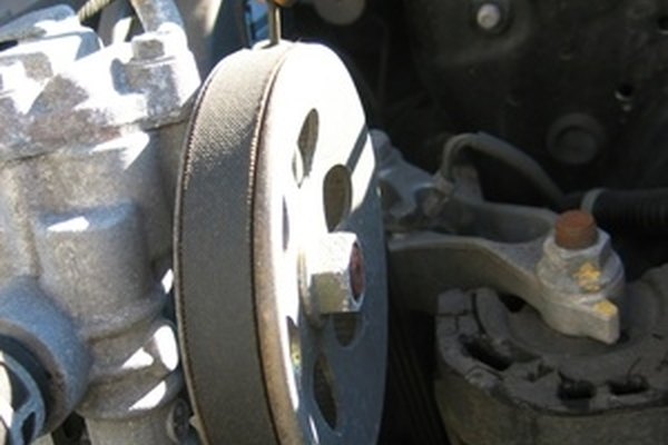
An automotive alternator is a three-phase generator with a built-in rectifier circuit consisting of six diodes. As the sheave (most people call it a “pulley”) is rotated by a belt connected to the automobile engine’s crankshaft, a magnet is spun past a stationary set of three-phase windings (called the stator), usually connected in a Y configuration. The spinning magnet is actually an electromagnet, not a permanent magnet. Alternators are designed this way so that the magnetic field strength can be controlled, in order that output voltage may be controlled independently of rotor speed. This rotor magnet coil (called the field coil, or simply field) is energized by battery power so that it takes a small amount of electrical power input to the alternator to get it to generate a lot of output power.
Electrical power is conducted to the rotating field coil through a pair of copper “slip rings” mounted concentrically on the shaft, contacted by stationary carbon “brushes.” The brushes are held in firm contact with the slip rings by spring pressure.
Many modern alternators are equipped with built-in “regulator” circuits that automatically switch battery power on and off to the rotor coil to regulate output voltage. This circuit, if present in the alternator you choose for the experiment, is unnecessary and will only impede your study if left in place. Feel free to “surgically remove” it, just make sure you leave access to the brush terminals so that you can power the field coil with the alternator fully assembled.
ILLUSTRATION

INSTRUCTIONS
First, consult an automotive repair manual on the specific details of your alternator. The documentation provided in the book you’re reading now is as general as possible to accommodate different brands of alternators. You may need more specific information, and a service manual is the best place to obtain it.
For this experiment, you’ll be connecting wires to the coils inside the alternator and extending them outside the alternator case, for easy connection to test equipment and circuits. Unfortunately, the connection terminals provided by the manufacturer won’t suit our needs here, so you need to make your own connections.
Disassemble the unit and locate terminals for connecting to the two carbon brushes. Solder a pair of wires to these terminals (at least 20 gauge in size) and extend these wires through vent holes in the alternator case, making sure they won’t get snagged on the spinning rotor when the alternator is re-assembled and used.
Locate the three-phase line connections coming from the stator windings and connect wires to them as well, extending these wires outside the alternator case through some vent holes. Use the largest gauge wire that is convenient to work with for these wires, as they may be carrying substantial current. As with the field wires, route them in such a way that the rotor will turn freely with the alternator reassembled. The stator winding line terminals are easy to locate: the three of them connect to three terminals on the diode assembly, usually with “ring-lug” terminals soldered to the ends of the wires.

I recommend that you solder ring-lug terminals to your wires, and attach them underneath the terminal nuts along with the stator wire ends so that each diode block terminal is securing two ring lugs.
Re-assemble the alternator, taking care to secure the carbon brushes in a retracted position so that the rotor doesn’t damage them upon re-insertion. On Delco-Remy alternators, a small hole is provided on the back case half, and also at the front of the brush holder assembly, through which a paper clip or thin-gauge wire may be inserted to hold the brushes back against their spring pressure. Consult the service manual for more details on alternator assembly.
When the alternator has been assembled, try spinning the shaft and listen for any sounds indicative of colliding parts or snagged wires. If there is any such trouble, take it apart again and correct whatever is wrong.
If and when it spins freely as it should, connect the two “field” wires to a 6-volt battery. Connect a voltmeter to any two of the three-phase line connections:

With the multimeter set to the “DC volts” function, slowly rotate the alternator shaft. The voltmeter reading should alternate between positive and negative as the shaft it turned: a demonstration of very slow alternating voltage (AC voltage) being generated. If this test is successful, switch the multimeter to the “AC volts” setting and try again. Try spinning the shaft slow and fast, comparing voltmeter readings between the two conditions.
Short-circuit any two of the three-phase line wires and try spinning the alternator. What you should notice is that the alternator shaft becomes more difficult to spin. The heavy electrical load you’ve created via the short circuit causes a heavy mechanical load on the alternator, as mechanical energy is converted into electrical energy.
Now, try connecting 12 volts DC to the field wires. Repeat the DC voltmeter, AC voltmeter, and short-circuit tests described above. What difference(s) do you notice?
Find some sort of polarity-insensitive 6 or 12 volts loads, such as small incandescent lamps, and connect them to the three-phase line wires. Wrap a thin rope or heavy string around the groove of the sheave (“pulley”) and spin the alternator rapidly, and the loads should function.
If you have a second alternator, modify it as you modified the first one, connecting five of your own wires to the field brushes and stator line terminals, respectively. You can then use it as a three-phase motor, powered by the first alternator.
Connect each of the three-phase line wires of the first alternator to the respective wires of the second alternator. Connect the field wires of one alternator to a 6-volt battery. This alternator will be the generator. Wrap rope around the sheave in preparation to spin it. Take the two field wires of the second alternator and short them together. This alternator will be the motor:
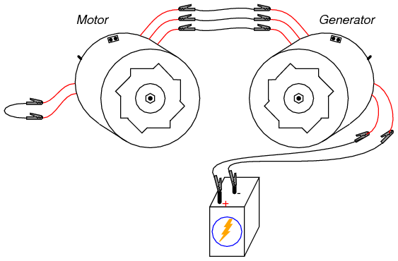
Spin the generator shaft while watching the motor shaft’s rotation. Try reversing any two of the three-phase line connections between the two units and spin the generator again. What is different this time?
Connect the field wires of the motor unit to the 6-volt battery (you may parallel-connect this field with the field of the generator unit, across the same battery terminals, if the battery is strong enough to deliver the several amps of current both coils will draw together). This will magnetize the rotor of the motor. Try spinning the generator again and note any differences in operation.
In the first motor setup, where the field wires were simple shorted together, the motor was functioning as aninduction motor. In the second setup, where the motor’s rotor was magnetized, it functioned as a synchronous motor.
If you are feeling particularly ambitious and are skilled in metal fabrication techniques, you may make your own high-power generator platform by connecting the modified alternator to a bicycle. I’ve built an arrangement that looks like this:
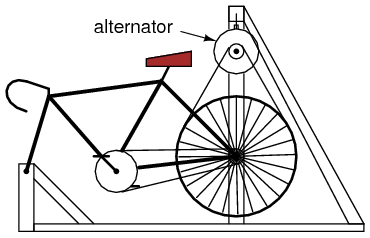
The rear wheel drives the generator sheave with a long v-belt. This belt also supports the rear of the bicycle, maintaining a constant tension when a rider is pedaling the bicycle. The generator hangs from a steel support structure (I used welded 2-inch square tubing, but a frame could be made out of lumber). Not only is this machine practical, but it is reliable enough to be used as an exercise machine, and it is inexpensive to make:

You can see a bank of three 12-volt “RV” light bulbs behind the bicycle unit (in the lower-left corner of the photograph), which I use for a load when riding the bicycle as an exercise machine. A set of three switches is mounted at the front of the bicycle, where I can turn loads on and off while riding.
By rectifying the three-phase AC power produced, it is possible to have the alternator power its own field coil with DC voltage, eliminating the need for a battery. However, some independent source of DC voltage will still be necessary for start-up, as the field coil must be energized before any AC power can be produced.
XXX . XXX 4 zero null What is the function of a diode in a generator? How does it work in the circuit?
I believe we are referring to the “rectifier diodes “ used in Alternators. As you know, according to the principle of generation of AC, a magnetic field is required. To produce this magnetic field, we use diode disc assembly, which consists of recrifier diodes ( equal number of forward and reverse biased diodes). The Self excited Alternator has two sections, 1) Exciter Field 2) Main field. The Alternator, starts using the principle of Residual magnetism , but to maintain generation of AC, the Main Feild Windings or the rotor windings require to be magnetised ( Brushless Alternator). Hence the AC which is produced by the Exciter System is fed to the diode disc assembly and the rectified output is fed to the Main field windings (rotor) to magnetise the same. When this field is rotated inside the Stator ( Armature Windings) , AC gets induced in the Armature windings.
There is another diode, which is used in the battery charging application. The DC battery used in DG Sets, is charged using a Dynamo coupled with the Engine flywheel. This dynamo is used to charge the battery and a diode is used between the same, to restrict charging in uni direction.
Rectifier diodes are electronic devices that allow electrical current to flow in one direction only. Because of this electrical property, diodes are used to convert alternating current electrical energy into direct current electrical energy. In an automotive electrical system, diodes can be found in several places, including the alternator. Alternator diodes perform three critical functions for the automotive charging system.
An alternator converts mechanical energy into electrical energy by creating a variable electromagnetic field. This field is induced across alternator windings, and creates an alternating current signal. However, the electrical devices in a car require direct current electrical energy.
The electrical energy passes through a device called a rectifier, which is made up of six or more diodes. The rectifier converts the alternating current energy produced by the alternator into direct current energy the automobile can use.
Simple function generators usually generate triangular waveform whose frequency can be controlled smoothly as well as in steps.
This triangular wave is used as the basis for all of its other outputs. The triangular wave is generated by repeatedly charging and discharging a capacitor from a constant current source. This produces a linearly ascending and descending voltage ramp. As the output voltage reaches upper or lower limits, the charging or discharging is reversed using a comparator, producing the linear triangle wave. By varying the current and the size of the capacitor, different frequencies may be obtained. Sawtooth waves can be produced by charging the capacitor slowly, using a current, but using a diode over the current source to discharge quickly - the polarity of the diode changes the polarity of the resulting sawtooth, i.e. slow rise and fast fall, or fast rise and slow fall.
A diode permits voltage to flow through it in one direction but blocks it from flowing back the other direction. It's like an anti-backflow valve in plumbing.
This is valuable in a portable generator, which is usually actually just a big alternator; alternators produce pure AC, but your generator's battery-charging circuit (and possibly control circuits, and ignition circuit) requires DC and can't tolerate AC. A diode permits only one phase of AC to flow, effectively converting it to DC.
This is valuable in a portable generator, which is usually actually just a big alternator; alternators produce pure AC, but your generator's battery-charging circuit (and possibly control circuits, and ignition circuit) requires DC and can't tolerate AC. A diode permits only one phase of AC to flow, effectively converting it to DC.
Alternator as in cars have a field coil and 3 windings for the output. The out is AC but whats called 3 phase AC. Each winding is 120 degrees apart . This allow three phase AC bridge rectification which need 6 rectifiers. Thats what in all alternators. This make DC with an AC ripple but does not need a big capacitor as in single phase rectification. There is also usually a soiid state regulator module that monitors the out put voltage and changes he current in the field coil to maintain a suitable voltage to charge the battery. this is typically 13.8 to 14.5 volts. It easy to check a bad alternator in a car. With the engine running a little above idle the output should be 13.5 to 14.5 volts If you measure less than 13 volts the alternator is probably bad. current cannot flow into a 12 volt battery with a low alternator output.
As a wave shaper. It is easier to generate square waves than sinewave directly. But use diodes to waveshape square waves generated into sinewaves. This is the method used in all modern generators. Diode is used to round off the sharp edges of the square wave.
Where in the circuit is the diode located? It could be part of the excitation circuit where output current is converted to DC using diode and fed to the rotor to create magnetic field on rotor. There would be residual magnetic field on rotor that would be enough to create a small output voltage which would be enough to provide excitation current to rotor boosting the output which further increases excitation until rated terminal voltage is reached.


INTRODUCTION
In the last two decades alternators have replaced generators in motor vehicles. The reasons are many: output current can be produced at lower rpm, voltage can be more accurately' controlled with solid state regulators, alternators need less maintenance, and they cost less to manufacture.
When modified, auto alternators can provide variable direct current at 0 to 120 volts for battery charging, hot charging, light arc welding, or for running AC-DC appliances and lights. Another simple modification provides AC power to run some transformer-operated appliances. If you know the secrets of its operation and the modifications possible, the small low-cost alternator can become a versatile power plant.
BASIC CONSTRUCTION
The old-fashioned generator contains a wound stater which produces a constant magnetic field in which a revolving coil of wire, called an armature, turns. A commutator on one end of the armature made up of many individual brass segments passes the generated current to the outside world through carbon brushes.

Because commutator segments must be electrically insulated from one another, they can not be fabricated from a single -block of metal. Each commutator segment must be individually attached to the armature shaft. This is a source of mechanical weakness. When the armature is rotated at high RPM, centrifugal force can cause the commutator to explode, throwing segments in all directions.
To prevent explosions, the generator is usually driven at less than engine speed. An auto engine may turn 5000 RPM, but the generator must be geared to a maximum 2500 rpm for safety's sake. As a result, the generator turns so slowly at low engine rpm that it produces little or no current.

A modern alternator, like the generator, contains both moving and stationary coils of wire. In the alternator, however, the moving coil, called the rotor, uses current supplied through slip rings to generate a moving field. Power is extracted from the stationary field coils.
Slip rings replace the weak generator commutator. The rotor coils themselves are encased in a strong soft iron shell making the whole assembly much stronger than the generator armature. The net result is that alternators can be driven to much higher speeds without danger of explosion. In fact, alternators are usually driven at up to twice engine speed some running at 8000 rpm or more. At low engine rpm the geared up alternator turns much faster than a comparable geared down generator. The net result is that the alternator can begin producing useful charging current at lower engine rpm than can the generator.

A coil of wire rotating in a magnetic field produces an alternating current with a frequency dependent on how fast the coil turns, one cycle being produced per revolution. A generator armature uses a commutator to mechanically switch rotating windings in and out of automobile's electrical system to produce direct current.
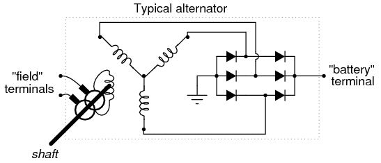
The three separate stationary windings of the typical auto alternator produce three-phase alternating current. Rather than use a commutator to mechanically convert AC to DC, the alternator uses six diodes in a full-wave bridge rectifier circuit. In essence the diodes are solid state switches with no moving parts, making them maintenance-free and explosion proof.
The alternator output voltage can be controlled or regulated by varying the rotor current. Regulators sample the output voltage and automatically change the intensity of the rotating magnetic field by adjusting the current fed to the rotor through the slip rings. The adjustments are made in such a way so as to bring the output voltage to the desired level.
THREE-PHASE POWER
Surprisingly, alternators are constructed with three sets of field windings positioned evenly at 120 degree intervals inside the frame. Such construction produces three-phase AC. But why three-phase?
If we look at the effect of diodes on a single-phase-AC current, we see that the output is a series of DC pulses. True direct current is completely smooth. The output of the diodes (rectified AC) is bumpy , and is said to possess ripple

When the rectified DC from each of the three-phase windings is added together or superimposed, the peaks overlap to produce a much cleaner DC with much less ripple. Lead-acid auto batteries last longer when charged with pure DC than high ripple rectified DC. Generators may be a mechanical and electrical nightmare, but they put out very clean DC. Three-phase windings were designed into alternators to produce DC of great purity.
Many alternators connect one lead of winding to a common point called a neutral. The other lead of each winding is connected to a pair of diodes. Three windings each using two diodes accounts for the six diodes found on most alternators.
Newer alternators particularly high current models, use two additional diodes on the neutral connection to sample alternator output voltage for use by the regulator.
In the future internal mechanical construction, electrical circuits, regulator operation and physical location will probably change somewhat. But basic alternator theory will not change. The exact details for the alternator you have can usually be found in a standard auto repair manual such as Motor's or Chilton's. Often you'll get instructions on dismantling and repairing alternators as well.

The diagrams in this booklet are general and should apply to all alternators. Again, refer to a recent auto manual for details on your particular alternator should you have problems.
REGULATORS
Early alternators used relays to regulate their output voltage much like those used on generators. When lower cost, more reliable solid state devices became available, electronic regulators became standard.
Although most regulators are factory set to force an alternator to produce 12 to 14 volts, they can be modified or new regulators custom built to provide almost any voltage up to 130 volts once their operation is understood.
If we were to run an alternator at some fixed rpm, we would find that changing the intensity of the rotating magnetic field would change the output voltage of the alternator. We can change that magnetic field by changing the amount of current flowing through the slip rings into the rotor. Since the resistance of the rotor windings is constant, merely changing the input voltage to the rotor will change the current flowing into the rotor by a proportionate amount.
Suppose we have alternator-spinning at 2000 rpm. We have it attached to some electrical-load drawing say 10 amps at 12 volts. Let's assume ; that the rotor is using 1 amp at 4 volts. Suppose we increase the electrical load: so that we now need 15 amps. Due to internal electrical resistance of the whole system, the voltage falls to 11 volts. To get the output voltage back up to 12 volts we must increase the rotor magnetic field intensity. So we adjust the rotor voltage up to 6 volts and in doing so, we find the rotor now drawing 1.5 amps of current. This increased current results in increased magnetic field which at 2000 rpm gives us an output of 15 amps at 12 volts. It is the job of the regulator to make these adjustments quickly and automatically.
Let's suppose that we set the rotor current at its maximum value, say 3 amps at 12 volts, and varying the rpm. At low rpm, the output voltage might be only five volts. As the rpm comes up, the output voltage would hit 12 volts then 25, then 50, and at top end, over 100 volts. Alternators can sometimes put out 140 volts when driven at top rpm.
As you can imagine, when the alternator is running at low rpm, the alternator is putting maximum voltage and current into the rotor so that the alternator output voltage will come up to 12 volts. When the rpm starts to pick up so that the voltage starts to climb above 12, the regulator starts cutting back the voltage and current into the rotor. At very high rpm, the regulator is supplying the rotor with very little current, so that the output voltage remains at a constant 12 volts.
An electronic regulator provides continuous and instantaneous adjustment of rotor current by sampling the alternator output voltage and by comparing it against a internal standard reference. When output falls, a small current is sent to transistor B which amplifies it and sends it to transistor A which acts as a valve in controlling the heavy current flow from the battery to the rotor.
Input voltage to the regulator is usually a steady 12 volts whereas output to the rotor varies from zero to 12 volts to control rotor current. Many rotors-have a winding resistance of about 3 or 4 ohms, which causes a current of 3 to 4 amps to flow at 12 volts (calculated with Ohm's law)
Suppose that to get 12 volts out of an alternator we need to pump 2 amps of direct current into the alternator's rotor which has an internal resistance of 3 ohms. What would the rotor voltage have to be? We can calculate it with Ohm's law:
volts = amps x ohms
= 2 x 3
= 6
The regulator passes 2 amps but has to eat up the difference between supply voltage, 12 volts, and rotor voltage, 6 volts or 6 volts. How much power is this? We can do another simple calculation:
watts = amps x votes
= 2 amps rotor current x 6 volts difference
= 12
This 12 watts of power is turned into heat, and if the regulator is to be kept cool and working properly, it must have heat-dissipating fins or should be mounted to a large heat sink such as a fender or firewall where destructive heat can be carried away.
Regulators use Zener diodes to provide a stable reference voltage. A voltage divider - the three resistors labelled C - extracts a preset fraction of the voltage for comparison against the Zener. For example, a regulator might have a 6 volt Zener in its circuit. To provide a regulated 12 volts, the resistive voltage divider is set to extract 1/2 of the sample voltage. When 12 volts is produced, half of 12, or six, is compared against the 6 volt Zener. They are equal; no change is made in rotor current. If output voltage falls to 8, the Zener is compared to 1/2 of 8, or 4 volts, and the regulator output current is increased to compensate. If output rises above 12, the regulator transistor is shut down enough to bring the output voltage back down.

Electronic regulators are superior to the old triple relay regulators used on generators. Obviously, there are no contacts to burn. While the older regulators would click in and out at the rate needed to hold output fairly steady, the solid-state regulators provides smooth quiet service, providing small continuous changes in rotor current. As long as the electronic unit kept cool, it should never need any service.
Alternator rotors are usually very rugged. Specially shaped poles create multiple magnetic poles from a single rotor winding. For instance, some Delco alternator have 8 alternating pairs of poles folded back from either end. With a single revolution of the rotor, the stater windings are hit with eight magnetic fields, producing eight cycles of alternating current. This is probably done to increase alternator output at very low rpm with limited rotor current. At normal running speeds the frequency of the alternating current fed to the diodes is usually several hundred cycles per second in frequency. HUNDREDS --- anything but the 60 cycles you get from a wall outlet.
Again, alternators are exceptionally strong allowing them to be overdriven at high rpm. They will produce useable current at lower rpm, and high voltage at high rpm if the rotor current is turned to maximum. High frequency three-phase AC is fed to solid state diodes to produce low ripple DC.

MODIFICATIONS
You'll see ads in many magazines promoting a simple device which when added to an auto alternator will allow you to get 3000 watts of DC to run AC-DC type appliances such as power drills, saws, and lights. This so-called wonder has been sold at prices from a few dollars to more than $25. You can build one for a couple dollars.
The secret of this magical little box is extremely simple. A switch puts bypasses the regulator putting 12 volts into the alternator rotor while transferring the alternator output from the auto circuit to an outlet installed in the box. When the auto engine rpm is increased, the voltage comes up to 120 volts. The device, therefore is nothing more than a switch and an outlet.
As we just discussed, alternator output voltage increases as the rpm goes up. It is the job of the regulator to cut back rotor current as rpm increases so that alternator output voltage stays at a constant 12 to 14 volts. The switch in the wonder box prevents the regulator from doing its job. As rpm increases so does the alternator output voltage. Some of the more expensive boxes have a volt meter to monitor voltage.
The diodes, also called rectifiers, are solid state devices which have low internal resistance --- that is, they eat up very little of the current flowing through them. These days solid state diodes are easy to build and therefore, low cost.
Diodes have two ratings: PIV and amperage. Amperage rating tells you how much current the diode can handle continuously. All diodes have some resistance, and at high current levels some power is converted to heat by this resistance. The ability to get rid of the waste heat determines how much current the diodes can handle. Remember, waste heat is determined by the current flowing. It has nothing to do whatsoever with voltage.
PIV, peak inverse volts, tells you how much voltage the diode can withstand before its internal insulation breaks down. A diode rated at 100 PIV can be used in circuits to 100 volts. A voltage of 200 volts at a tiny fraction of an amp for even a thousandth of a second (a voltage spike) can destroy the diode.
It's usually a good idea to overrate diodes. If you want a diode to handle 10 amps at 100 volts, it would be wise to use a diode rated at 15 amps and 200 PIV. Diodes used on modern alternators can usually handle the high voltage. It is entirely possible, however, that in bringing the alternator voltage up that you could blow the diodes in the alternator. This means having to replace the diodes. They're not expensive, but it can be a hassle pressing out old diodes and putting in new ones. Refer to an auto manual for detailed information.

If we have a 30 amp alternator and we've revved it up to get 120 volts we can calculate the power available:
watts = volts x amps
= 120 x 30
= 3600
The $25.00 control box that you must buy (so the ads say) consists of a four-pole double-throw switch, a 30 amp fuse, an outlet, and an optional 0-150 volt DC meter. Throwing the switch puts 12 volts into the alternator rotor through one set of contacts, cuts the regulator out of the circuit, and switches the alternator output from the auto electrical system through a 30 amp fuse to a standard outlet. A meter can be connected across the outlet to show how fast the engine must turn to give 120 volts.
When producing the higher voltage, the battery supplies 3 to 4 amps to the alternator but receives no charge in return. Even with this drain, the unit can be run for many hours before the battery comes noticeably discharged. But remember! You cannot run the system this way indefinitely. An 80 amp-hour battery would become fully discharged in 20 hours with a 4 amp draw. At some point you'll have to switch back to normal operation to recharge the battery. And! Auto batteries can be seriously damaged if allowed to become fully discharged.

Suppose we're producing 3600 watts. Since 746 watts equals one horsepower, it's a simple matter to calculate the mechanical power needed:
horsepower = watts / 746
= 3600 / 746
= 4.8
By the time you add power lost in bearings and fan windage, you'll probably need 5 1/2 horsepower.
Revving up an auto engine just to produce 5 horsepower is wasteful. Many people have found that a small power plant can be built from a 5 to 8 horsepower engine, an alternator, a regulator, a motorcycle battery, switches, etc. The engine's governor can be set to hold a steady rpm, and for longer periods of use, this small power plant should use less gas since it is running closer to full load.
When building a power plant, it is advisable to get an alternator from a large late-model air conditioned automobile. Many of these units can produce 50 to 60 amps which can be used for light arc-welding. It is best to include a 0-60 ammeter in your power plant circuit to be sure you come close to but do not exceed the alternator's capacity. While it is possible to burn out the alternator windings, the diodes usually melt first.
Since gas engines seldom run above 3500 RPM and since an alternator must turn about 5000 RPM to produce 120 volts, the unit must be Geared up. Putting a larger pulley on the engine will achieve a gear up whose ratio is proportional to the ratio of the pulley diameters. For instance, an engine running at 2600 RPM must be Geared to turn the alternator at 5200 RPM, We need to gear the alternator up by
5200 / 2600 = 2
a factor of 2. Therefore-the pulley on the engine should be twice the diameter as the pulley on the alternator.
The whole power plant can be built on a plywood base, and if a motorcycle battery is used to save weight, the unit can be quite small and easily portable, When the unit is producing the higher voltages, the battery provides the necessary rotor current. After a few hours of Operation, it is advisable to throw the regulator back into the circuit and recharge the battery.
With simple modifications it is possible to charge 12 volt batteries. Quick batteries at 30 to 40 volts and high current, arc-weld at 50 to 60 volts, and run AC-DC appliances at 120 volts.
SPECIAL REGULATORS
You may be interested in using an alternator to convert wind or water power to electricity. In such systems it is common practice to charge a Bank of Storage batteries, so that power is available even when the wind isn't blowing, or water levels are low.

This arrangement allows five storage batteries to be charged as a single 60 volt 80 amp-hour battery, but provides 12 volt 400 amp-hour to drive inverters or appliances. Knife swtiches should be used to switch the bank. All switches should be brought to the open position, and then all switches should be moved to their new position. Most toggle switches will not work because they have no neutral position, and cannot handle heavy currrents.
Most of these systems use a standard 12 volt system which works well for average service, but seldom allows conversion of large amounts of available rotational energy.
Suppose, for example a windmill, waterwheel, or treadmill provides one horsepower of mechanical power to our 60 amp alternator. At 12 volts and 60 amps we get 720 watts out -- almost one horsepower.
Now suppose that more energy is available because of high winds or higher water head. The mill or wheel can now provide two horsepower, but because we cannot exceed 60 amps without overheating wiring or popping diodes. We only provide the maximum 720 watts at 12 volts. The additional horsepower is available, but not convertible.
Most storage banks are built from many batteries in parallel to provide 12 volts with at least 200 amp-hour capacity. Suppose that for those periods of high wind or water, that the batteries are connected in total 36 volt battery pack and that the alternator is regulated by a special 36 volt regulator. Suppose, too, that we run the current all the way up-to 60 amps output. Now we are converting 36 volts X 60 amps, or 2160 watts -- almost 3 horsepower. If the voltage could be run up to 120 volts, total watts at 60 amps would be 7200, ten times that available at 12 volts from the very same alternator.
At first impression you might think that the alternator could never handle it, but it can. Voltage is limited by the thickness of insulation on the windings and breakdown (PIV--peak inverse volts) voltage of the-diodes. Current through the windings and diodes produces heat. 'As long as the manufacturer's rated maximum 'current is not exceeded, the windings and diodes will not overheat and melt. If you can provide the mechanical power at an excess of 5000 shaft RPM, you can extract the 7200 watts without electrical damage. REMEMBER: The waste heat generated in both the diodes and windings is proportional to the current being produced whether it be at 12 or 120 volts.
Mechanical damage is another consideration. Since 7200 watts is almost 10 horsepower, we must question the ability of the alternator bearings to handle this much power.
At this power level, V-belt drive will not work for two reasons. First, the usual auto fanbelt is too small to handle the strain of 10 horsepower. It would snap under the tension. Second, V-belts require much friction on the sides of the pulley to transfer power, and this means the bearings are heavily loaded with a pull to one side. At 10 horsepower, they would probably wear out in a hurry. For these high power levels you'll have to consider chain and sprocket drive which can handle the higher power levels more efficiently with much less bearing loading.
High voltage regulators can be built with little difficulty. If it were not for the fact that most auto regulators are sealed, they could be simply modified. Nevertheless, the regulator circuits used on low voltage hobbyist power supplies will do the job. Schematics can be found in the electronics magazines, Radio Amateur's Handbook, and books on electronic power supplies. The basic design has been around for years.

In the typical regulator circuit shown, the resistors A, B and C make up a circuit called a voltage divider. Its is function to extract a fraction of the alternator output voltage and compare it against an internal voltage reference.
From ground to the high side in the diagram we have 140 + 40 + 140 ohms or 320 ohms total. If we assume that variable resistor B is set to 20 ohms, we see that from ground to line X we have 140 + 20 ohms or 160 ohms. Therefore, on line X we will see 160/320 -or 1/2 of the high-side voltage. In other words, if the high side had 12 volts on it, measured from ground, we would see 6 volts on line X measured from ground. Moving the variable resistor arm closer to ground would lower the voltage on line X. The variable resistor selects the exact fraction or percentage of voltage that is to be compared with the internal reference.
Lets suppose the Zener diode, our internal reference, produces 6 volts. And let's assume that our voltage divider is set at 50%. When the high side is at 12 volts, the divider takes 50% or half, 6 volts and compares with the Zener. Since the Zener is at 6 volts, there is no difference, and the regulator takes no action.
If high side drops to, say, 10 volts, the divider takes half or 5 volts. Now we have a one volt difference when compared to the unchanging 6 volt Zener voltage. This one volt drop causes the transistors in the rest of the circuit which act as valves to open a little more and let more current into the rotor to increase the revolving magnetic field and bring output voltage back up. This continues until the high side voltage comes back up to 12.
If output voltage goes up, much the same thing happens. The difference between the voltage sample and the Zener is of opposite polarity, so the transistors shut off to the degree necessary to force alternator voltage back down.
In practice these actions take place smoothly and continuously. Our explanation is simplified, but fairly accurate.
If you change the percentage setting of voltage divider resistors, you can change the alternator voltage. Suppose you change the divider setting so that 20% of voltage is extracted what would the output of the alternator be? To find out divide the Zener reference voltage by the percentage:
output volts = zener / percentage
= 6 volts / .20
= 30
The regulator will take 30 volts, extract 20% with the voltage divider which comes to 6 volts. Compared with the Zener 6 volts, no corrective action will be taken. Any change from 30 volts will create a correction voltage that cause the transistors to open or close as necessary until voltage comes back to 30.
Suppose we set the voltage divider at 80%. What output voltage would we get from the alternator?
output volts = zener / percentage
= 6 volts / .80
= 7.5
In this case we've dropped from 12 to 7 1/2 volts.
The practical percentage ranges of voltage dividers usually run from 40% to 60%. This might translate into settings of 10 to 15 alternator output volts.
To get beyond this range we need to change the Zener and perhaps the divider range as well. Consider for a minute if we installed a 50 volt Zener diode. At 50% divider setting output voltage would be
output volts = zener / percentage
= 50 / .50
= 100
And if we again consider a practical-40%; to 60% range, the alternator could be regulated to produce a constant voltage in the 83 to 125 volt range.
The same resistors used for the 12 volt regulator could not be used in a high voltage regulator. At 120 volts, you'd be putting 10 times as much voltage across them, causing 10 times as much current to flow. Since power through a resistor is equal to the square of the current times ohms of resistance, you'd be putting 100 times more power into the resistors. In other words, they'd smoke and burn! In practice you'd probably want to increase the resistance 100 times. That would limit the current flow and power into resistors to its original value when run at 12 volts.
It is not the purpose of this manual to be a course in electronics design. The principles involved in designing and building a basic electronic regulator can be found in a great many books on electronics and power supply design. You should read up on the subject before designing a regulator.
One good book worth consulting is Regulated Power Supplies by Irving M Gottlieb, published by Howard W Sams, Indianapolis IN. There are many others.

MODIFICATION FOR 110 VOLT AC
Alternators produce rectified DC power. If we tap the leads attached to the diodes, we can obtain 120 volt AC power. Some, but not all transformer operated appliances such as TV's, radio's, fluorescent lights might be possibly be run on this AC.
AC coming from the alternator is very high frequency and a great many transformers will overheat at the high frequency. The only way to tell is to plug the device in for a few seconds, unplug it, and then feel the transformer or ballast to see if it is overheating. Even this is risky. Unless you're willing to take the chances involved, you might be better off converting an induction motor to provide pure 60 cycle AC, described later on.
If you'd still like to give it a try, conversion is a simple matter of removing diodes, and connecting leads. In most alternators two wires are soldered to each of the diodes. Remove both from the diode and attach it to one of three leads. When wired as shown, two outlets with a common ground can be powered.
Forget about running motor-driven appliances-unless they use universal AC-DC brush type motors. Ordinary induction motors are designed for 60 cycles AC. At different frequencies they will run at different rpm if at all, and will quite possibly overheat or be destroyed.
REWINDING THE WINDMILL USE...
Alternators usually loaf along at low RPM, and do not usually begin to produce a lot of power until they exceed about 1000 RPM. This lower RPM limit can be dropped by rewinding the alternator's stationary coils. An alternator modified in this way used on a windmill, for instance, can begin producing power at slower wind speed, realising greater total power output over a period of time.
For example, a 45 amp Chrysler alternator can be modified by removing each of the 16 turn coils, and by replacing them with a smaller diameter wire so that each coil is made up of more turns. Number 20 plastic coated wire (such as Belden polythermaleze) obtained from a motor shop can be used to wind coils of 25 to 26 turns before all available slot space is used. Coils are set by dipping in motor varnish and baking with low heat until hardened. Small diameter wire reduces maximum current available. Here, No. 20 will handle only about 25 amps with good cooling, but the extra windings allow the alternator to begin charging at a much lower RPM.
One good reference on motor and generator rewinding is Armature Winding and Motor Repair by Daniel Breymer available from Lindsay Publications.
BUILDING A 60 CYCLE ALTERNATOR
Theory says that any generator can be used as a motor and vice-versa. If this is so, could we take a common 1/3 hp induction washing machine motor and use it to produce 120 volts 60 cycle power? The answer is yes!
But we have two problems to solve. First, we must drive the motor faster than its nameplate rpm to get 60 cycle. Second, when we start the unit, we may have to hit the coils with a DC pulse to start it generating.
Induction motors have no physical connection between the stationary winding and the squirrel cage rotor. The electricity flowing in the rotor is created by transformer action because the magnetic field in the stater winding is revolving at 1800 rpm while the rotor is revolving at 1725 rpm. The 75 rpm difference (4 to 5%) causes a current to be induced into the rotor.

When used as an alternator, the motor must be driven 4-5% faster than the 1800 rpm synchronous speed. This comes to about 1880 rpm, faster or slower depending on alternator loading. When the driving speed is exactly right, the alternator will be producing exactly 60 cycle power.
Some motors will begin generating power as soon as they're driven because there's a small amount of residual magnetism remaining in the rotor and windings. If generation doesn't begin by itself, you'll probably have to hit the windings with a pulse of DC current to get it started. A switch connected to a 12 volt battery will probably be adequate, although in some cases you may need as much as 60 volts to do the job.
A split-phase capacitor-run motor can be used as is. But other motors will probably need a capacitor in the 8 to 100 mfd range. Trial and error will determine the exact size. Make sure the capacitors are rated at 250 to 300 volts AC.
Not all motors will work properly, and we don't really know why. Fortunately, most do.
You won't be able to get as much power out of the motor as the nameplate indicates. To find exactly how much power you can get, connect ordinary light bulbs to your new alternator one after another. At some point the alternator will suddenly stop working, indicating that it is overloaded. This response can sometimes be a hassle, but it makes the alternator burn-out proof.


To get large amount of AC out, you will need a large motor --- over a horsepower. You may be able to find a large single phase motor on a table saw or on farm machinery. But you may have to use a three-phase motor. With a three-phase machine you'll need a capacitor across one of the legs, but not on all three. Remember though, Three-phase motors will generate power from 208 volts on up. To get 110 volts you'll have to use a large transformer to step the 208 down to 110, and that's not very practical.
The frequency of the AC out will vary as the engine rpm varies. How are you going to know when you have 60 cycle? One easy way is to use a motor driven clock. Plug it into the circuit and leave it there. It only draws a few watts. Compare the second hand with the seconds counter on a quartz wrist watch. If the motor clock is running slow, the AC is less than 60 cycle. Adjust engine rpm until the clock is keeping accurate time.
In conclusion, you can generate small amounts of 120 volt 60 cycle that will drive anything from your TV to your refrigerator using an induction motor as an alternator. It will take experimentation. When it works (which is most of the time), it works very well. It's certainly worth trying.
XXX . XXX 4 zero null 0 1 2 wireless energy for electronic and electric car
It is safe to say that there isn’t and will never be an energy crisis, under the premise of new or free energy. Energy is all around us. Energy is free for the taking. How you get free infinite energy is so simple.
Our Sun emits electromagnetic energy and that energy showers down on us throughout the whole 24 hours, and if a energy receiving device (an antenna) can easily be built to harness and use this power it will not require devices for storing energy as would be necessary with devices using wind, tide or sunlight.
In one hour, or 3600 seconds, our Sun produces 1.4 x 10^31 Joules of energy or 3.8 x 10^23 kilowatt-hours. It’s been doing this for about 4.5 billion years and will continue to do this every second, of every minute, of every hour, of every day, of every year – for another 4.5 billion years.
That means free energy will be available to mankind for another 4.5 billion years.
Today, in 2012, we can remove every gasoline combustion engine and replace it with a zero emission electric motor. At the same time we can remove the gas tank, the fuel lines, the exhaust system, the water pump, radiator, and all emission control devices because an electric motor car doesn’t need them. We didn’t need them 81 years ago and we don’t need them now.
Nikola Tesla proved in 1931 that it is possible to power our vehicles without a drop of fossil fuel. He removed the gasoline engine of a Pierce Arrow and replaced it with an electric motor and drove for hours, at speeds as high as 90 mph. Today, 81 years later, it is still possible to convert any gasoline engine vehicle into an all-electric vehicle and it will operate for hours – without having to stop and recharge. Not a drop of oil, gasoline, hydrogen fuel, natural gas or water. No combustion engine. No exhaust system. No pollution.
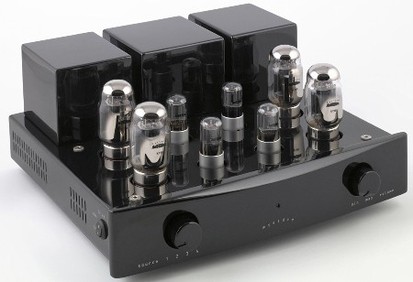
Modern Valve Amplifier
We don’t need them because electric motor cars don’t need a drop of gasoline or diesel. Because they don’t need or use a single drop of gasoline or diesel electric motor cars produce zero carbon (CO) emissions. No CO emissions means no smog and no contributing to global warming. No CO emissions also means the elimination of most respiratory diseases. That alone will save $billions in health care costs.
The fact that electric cars don’t need fuel tanks or fuel lines means the elimination of fuel leakage and fuel fires in an automobile accident. How many people have been burned alive, trapped inside their burning oil fuel vehicle? No amount of airbags are going to save you if your oil fuel tank or oil fuel line ruptures and ignites. Apart from the horrific consequences of driving around, strapped inside an oil fuel bomb, the fuel tank needs to be constantly filled up with very expensive ($4 to $5 a gallon) diesel or gasoline fuel. Can you afford to continue to pay $80 to $100 to fill up? How far can you go on $80 to $100 of oil fuel? Does it last you the week?
Electric cars have no rusting and pollution (CO) emitting exhaust manifolds, no catalytic converters, no O2 sensors, no mufflers and no tailpipes. How much does it cost you every year to replace those rusting oil fuel exhaust parts?
Electric motor vehicles have no radiators, no toxic radiator fluid, no coolant pump, no coolant lines and no radiator hoses. Electric motors don’t get as hot as oil fuel engines so they don’t need all those costly and bulky cooling system parts. That means if you drive an electric vehicle you won’t overheat and get stranded on the highway in rush hour traffic, during a heatwave.
You can run an electric vehicle indoors for hours or days and not kill (by CO asphyxiation) anyone. Try doing that with a oil fuel vehicle and you will no doubt send a lot of people to the hospital or to the morgue.
Whenever someone who owns a Big 3 (Government Motors, Ford and Chrysler) manufactured oil fuel vehicle brags to me that their new vehicle is environmentally friendly I always tell them that if you truly believe that, prove it by parking it in their garage, with the garage door closed, the engine running and them sitting in it.
We didn’t need combustion engines 81 years ago and we don’t need them now. Let’s make 2012 the year the World got off oil.
TELSA HAD SUPPORT - WHAT HAPPENED?
Supported by the Pierce-Arrow Co. and General Electric in 1931, Tesla took the gasoline engine from a new Pierce-Arrow and replaced it with an 80-horsepower alternating-current (AC) electric motor with no external power source. At a local radio supply shop he bought 12 vacuum tubes, some wires and assorted resistors, and assembled them in a circuit box 24 inches long, 12 inches wide and 6 inches high, with a pair of 3-inch rods sticking out. Getting into the car with the circuit box in the front seat beside him, he pushed the rods in, announced, “We now have power,” and proceeded to test drive the car for a full week, often at speeds of up to 90 mph. His car was never plugged into any electrical receptacle for a recharge. As it was an alternating-current motor and there were no batteries involved, where did the power come from?
Tesla used the collection of vacuum tubes (also called a valve amplifier), wires and assorted resistors to build a radio wave receiver/amplifier 24 inches long, 12 inches wide and 6 inches high, with a pair of 3-inch rods 1/4” in diameter sticking out. The pair of rods that Tesla pushed in were used to close (complete) the circuit – like an on/off switch. The rod ends were most likely the positive and negative leads (connections) between the car antenna and and the radio wave receiver/amplifier. By pushing them into the box containing the radio wave receiver/amplifier the connection was completed allowing the radio waves that were received from the air by the antenna to flow through the receiver/amplifier to the electric motor.
Tesla’s electric control box worked much the same way as an electric guitar amplifier. Like the electric guitar amplifier the signal generated by striking a cord (string) of a guitar would travel from the guitar through the wire connecting the guitar to the amplifier and into the amplifier where the barely audible tone would then be amplified.
An electric guitar without an amplifier is essential an air guitar until it is plugged into an amplifier. The amplifier amplifies the sound wave generated by striking the strings of the electric guitar. That is basically how Tesla was able to amplify and convert the invisible electromagnetic radiation called radio waves into electricity to power the AC motor in the 1931 Pierce-Arrow. The word electricity comes from the fact that current is nothing more than electrons moving along a conductor, like an antenna, that have been harnessed for energy. Tesla used an antenna (an electrical conductor) and an amplifier to harness and then amplify energy.
An amplifier’s job is to take a weak audio signal and boost it to generate a signal that is powerful enough to drive a speaker, or in the above case, an electric motor. Today the component at the heart of most amplifiers is the transistor. Transistors have replaced Tesla’s vacuum tube (also called valve amplifier).
A transistor is a semiconductor device used to amplify and switch electronic signals and power. It is composed of a semiconductor material with at least three terminals for connection to an external circuit. A voltage or current applied to one pair of the transistor’s terminals changes the current flowing through another pair of terminals. Because the controlled (output) power can be higher than the controlling (input) power, a transistor can amplify a signal.
So today you can amplify a weak audio signal with transistors instead of valve amplifiers.
In case you didn’t notice, there is no mention that Tesla removed the alternator of the Pierce Arrow. It just stated that the gas combustion engine was removed and replaced with an 80-horsepower AC electric motor. Why is this significant? How was he able to drive for hours, at speeds as high as 90 mph without stopping to recharge? Because of the alternator. Alternators are used in all gas combustion engine automobiles to charge the battery and to power the electrical system when its engine is running. Even the Ford Model T automobiles from 1919 to 1927 had a 12 volt negative ground Delco style alternator .
It is entirely plausible that Tesla made use of the alternator to continually recharge the Pierce Arrow’s single 12 volt automotive battery and help supply sufficient power to the electric motor.
Alternators do not produce a set voltage. The faster the rotor in the alternator spins, the more the voltage increases. However, your vehicle’s electrical system is unable to operate if the voltage fluctuates constantly, so voltage is regulated using a voltage regulator that for most vehicles is set to 12 volts. Ford’s Model T had voltage regulators . Until the 1970s, automobiles used DC dynamo generators – – with commutators. With the availability of affordable silicon diode rectifiers, alternators were used instead. You can buy a 10mA 20kV High Voltage Diode HV Rectifier for a Tesla Ham for as little as $0.72
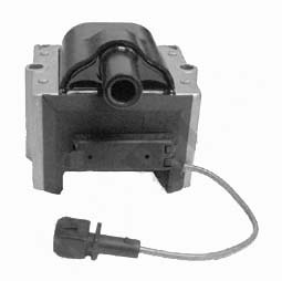
Ignition coils already existed back in the 1930s too. An ignition coil (also called a spark coil) is an induction coil in an automobile’s ignition system which transforms the battery’s low voltage to the thousands of volts (around 10 – 20kV) needed to create an electric spark in the spark plugs to ignite the fuel. It is also entirely plausible that Tesla used the Pierce Arrow’s ignition coil to transform the antenna receiver’s low voltage to hundreds of volts needed to power the electric motor. AC electric motors requires more than 12 volts of AC current. It doesn’t need 10-20,000 volts. So all Tesla needed to do is use the Pierce Arrow’s ignition coil to transform the very weak signal captured by the antenna (an electrical device which converts electric currents into radio waves, and vice versa.) into a constant 120 volts or the required voltage needed to power the 80-horsepower AC electric motor.
Electricians know what I am talking about and can easily replicate Tesla’s achievement. Tesla more than likely made use of the Pierce Arrow’s alternator and ignition coil and made it possible to drive for hours, at speeds as high as 90 mph.
TESLA AND HIS MYSTERIOUS VACUUM TUBES
Why did Tesla use so many vacuum tubes? He bought 12 vacuum tubes.
In electronics, the Darlington transistor (often called a Darlington pair) is a compound structure consisting of two bipolar transistors connected in such a way that the current amplified by the first transistor is amplified further by the second one. This configuration gives a much higher current gain than each transistor taken separately.
The Darlington Pair is renowned as a method for obtaining a very high level of current gain, using just two transistors. It is able to provide levels of gain that are not possible using single transistors on their own. The gain of the Darlington transistor pair is that gain of the two individual transistors multiplied together. This gives the Darlington pair a very high current gain, such as 10000, so that only a tiny base current is required to make the pair switch on.
A transistor is a semiconductor device used to amplify and switch electronic signals and power. A valve amplifier or tube amplifier is a type of electronic amplifier that makes use of vacuum tubes to increase the amplitude of a signal. Therefore, transistors and semiconductor devices replaced the vacuum tube to amplify a weak signal. So essentially, Tesla used 12 vacuum tubes paired up to obtain a very high level of current gain.
But the Darlington pair was only discovered decades later (in 1953). Or was it? Tesla used so many vacuum tubes to create a push-pull signal amplifier. A push-pull signal amp requires at least two tubes (a pair of tubes is the same as a pair of transistors or Darlington Pair) to operate, but can have more connected in parallel with each side, resulting in an amp with four, six, eight output or even 12 tubes for much higher power amplification. When the tubes are connected in parallel it is called a “parallel push-pull” amp.
In a push pull signal amp the power supply is connected to the center-tap of the transformer (An Ignition coil is like and can be used as a high voltage transformer) and a tube is connected to both the upper and lower end of the center-tapped primary. This allows the tubes to conduct on alternate cycles (Alternating current or AC) of the input waveform.
So in short – Tesla connected the antenna (an electrical device which converts electric radio waves into current – i.e. an infinitely free power supply) to the center-tap of the ignition coil of the Pierce Arrow. 12 vacuum tubes were then wired (connected) together in parallel and connected to the ignition coil. In this circuit, Tesla amplified the very weak radio wave signal and produced a very high voltage output. Enough to power the 80 HP AC electric motor for a full week, often at speeds of up to 90 mph.
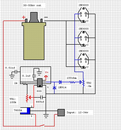
If you can power an electric motor using a few electronic devices and free radiant energy and power a very heavy automobile couldn’t you also use the same technology to power your home? The answer is yes.
If you can erect an antenna on a car and connect it to an ignition coil and transistors and amplify the antenna received weak signal into enough electrical energy to power a car you can also do the same and power your home.
If you can erect an antenna on a car and connect it to an ignition coil and transistors and amplify the antenna received weak signal into enough electrical energy to power a car you can also do the same and power your home.
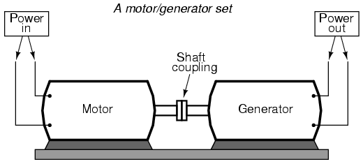
Mass produced gas powered generators can be stripped down and used as a Tesla free radiant energy receiver and electrical power generator. Remove the small gas combustion engine and replace it with a small electric motor. Connect the shaft of the small electric motor to the shaft of the rotor of the electric generator. Erect a TV or CB antenna on the roof of your house and connect (wire) it to a circuit box like the one Tesla made. Wire this circuit box to the electric motor and complete the circuit.
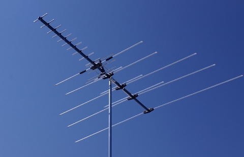
The key to unlimited free home energy is erecting the antenna above head height. Why? Physicists have determined that the earth has a negative charge which amounts to 400,000 columbs, yet six feet above the ground (above head height) the air is charged with more than 200 volts positive in respect to the ground. Your electrical outlets and home appliances are charged with 120 volts positive. An antenna is a free energy receiver. It receives free radiant energy and converts it into electric current. So an antenna erected on the roof of a house will tap into and immediately start receiving this free and infinite supply of 200 volts positive energy.
After all, an electric generator is a device that converts mechanical energy obtained from an external source into electrical energy as the output. The rotating rotor (mechanical) generates a moving magnetic field around the stator, which induces a voltage difference between the windings of the stator. This produces the alternating current (AC) output of the generator. So what Tesla did with a gas combustion automobile can be done with a gas combustion electrical power generator.
Tesla proved that you can drive a car for a full week using no fuel whatsoever. Tesla also proved that you can also power your home, using no fuel whatsoever.
Bottom line is, you will never need to buy fuel for you car or home again.

Everything on Earth is energy. Even the Earth and its atmosphere is energy. According Dr. Thomas Henry even empty space itself not only contains prodigious quantities of energy, but in fact was prodigious quantities of energy. Today we now know that one cubic centimeter of pure vacuum contains enough energy to condense into 10 to the 80th power to 10 to 120th power grams of matter! Thus the major part of Moray’s thesis that vacuum itself contains unlimited energy is vindicated today. In this sense empty space is like a gigantic, restless ocean of energy.
Earth is always referred to as ground when explaining electrical circuitry. Electrical current flows to ground or earth. The Earth – the ground we stand on, walk on, sleep on , play. run on, drive on and build on is negative electrically charged and acts as a spherical capacitor. The Earth has a net negative charge of about a million coulombs, while an equal and positive charge resides in the atmosphere –
Natural Resources Canada goes on to state:
“The electrical resistivity of the atmosphere decreases with height to an altitude of about 48 kilometres (km), where the resistivity becomes more-or-less constant. This region is known as the electrosphere. There is about a 300 000 volt (V) potential difference between the Earth’s surface and the electrosphere, which gives an average electric field strength of about 6 V/meter (m) throughout the atmosphere. Near the surface, the fine-weather electric field strength is about 100 V/m..”
The Canadian government is telling us that every meter of the electrosphere has a 6 V positive charge and near the surface, every meter of the atmosphere we breathe has a 100 Volt positive charge.
Wikipedia also states that Earth’s atmosphere is electrically charged. They disclose this with this statement – “The measurements of atmospheric electricity can be seen as measurements of difference of potential between a point of the Earth’s surface, and a point somewhere in the air above it. The atmosphere in different regions is often found to be at different local potentials, which differ from that of the earth sometimes even by as much as 3000 Volts within 100 feet (30 m). The electrostatic field and the difference of potential of the earth field according to investigations, is in summer about 60 to 100 volts and in winter 300 to 500 volts per meter of difference in height, a simple calculation gives the result that when such a collector is arranged for example on the ground, and a second one is mounted vertically over it at a distance of 2000 meters and both are connected by a conducting cable, there is a difference in potential in summer of about 2,000,000 volts and in winter even of 6,000,000 volts and more.”
sea of energy : We need only know how to tap into it to power everything we use. Moray even developed and successfully demonstrated a device that harnessed this free energy and powered 35 100-watt lamps and a 1200-watt iron simultaneously.
Moray’s device used twenty-nine stages of his special detector valves. His device was based on the discovery of a mixture that would act as a one-way gate for the high frequency oscillations of space, so that the energy could go through the material more readily in one direction than another. Electrons could flow in each valve, but was prevented from flowing back out.
What would only allow electrons to flow in one direction? A vacuum tube diode. now rarely used except in some high-power technologies and by enthusiasts, is a vacuum tube with two electrodes, a plate (anode) and cathode.
The most common function of a diode is to allow an electric current to pass in one direction (called the diode’s forward direction), while blocking current in the opposite direction (the reverse direction). Thus, the diode can be thought of as an electronic version of a check valve. This unidirectional behavior is called rectification, and is used to convert alternating current to direct current, including extraction of modulation from radio signals in radio receivers—these diodes are forms of rectifiers.
I don’t know about you but it would appear that Moray used vacuum tube diode as his special detector valves to tap into and harness the free electrical energy that surrounds us – 100 volts/meter of free energy.
I don’t know about you but it would appear that Moray used vacuum tube diode as his special detector valves to tap into and harness the free electrical energy that surrounds us – 100 volts/meter of free energy.


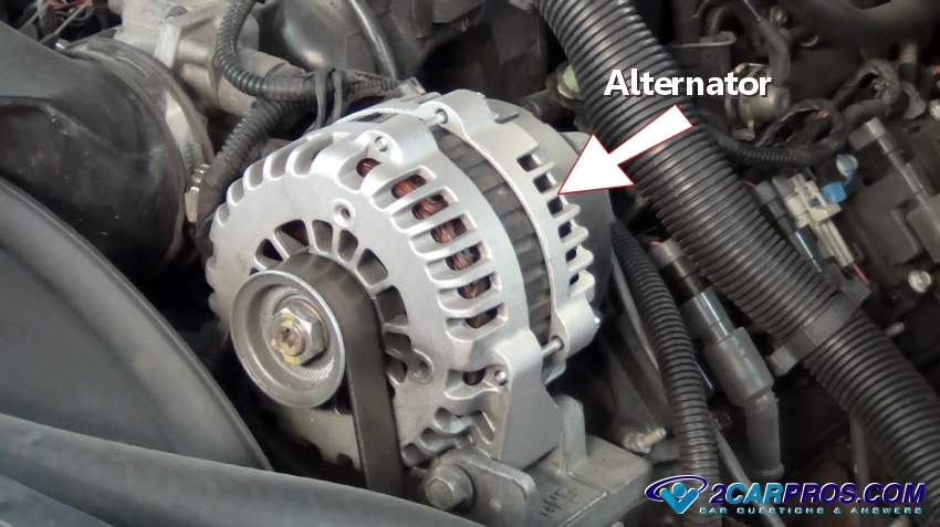
HOW TO TEST AN ALTERNATOR
Need to test your alternator? We are a team of ASE certified mechanics that have created this guide for you so you can save money or at least see what you are paying for when taking your car in for repairs. This simple guide shows you how easy testing an alternator is when using a voltmeter. Even if you don't have a meter you can still see if the alternator is charging by observing the headlights which is described at the bottom of the guide.
WHAT GOES WRONG?
Your alternator is responsible for charging your vehicles battery and keeping the electrical system energized when the vehicle is in operation. When it fails you will slowly lose electrical power until the engine quits running due to insufficient voltage that operates the ignition system which can leave you stranded.
Anytime you have a battery warning light on or you have just replaced your alternator or battery you should perform a voltage output test. Additional reasons for testing include a buzzing radio noise through the speakers signaling the alternator diodes have gone bad and are leaking AC voltage into the system. We will explain how to test for this later on in the guide.
If the battery is being overcharged it will cause a chemical reaction that smells like sulfur letting you know the voltage regulator has failed allowing the system to be overcharged. When an alternator fails not only will the battery light come on but it can cause the check engine or service engine soon warning lights to come on.
Never disconnect the battery while the engine is running to check the charging system. This can cause a major electrical system malfunction such as short circuit to the main computer. Removing the battery cable to test the charging system was used for vehicles made before 1976 and not today's vehicles. The battery is used as an electrical shock absorber which keeps the system stable. If you remove a battery cable it will cause a voltage spike that can damage major electrical components like the computer.
GETTING STARTED
Begin your testing with the vehicle on level ground, engine off and in park with the emergency brake set. Though you can see if the alternator is changing without a voltmeter it will need to be done at night using the headlight. Its best to have a voltmeter which is available from Amazon for about $25.00 bucks if you don't have one already.
A serpentine belt is used to turn the alternator stator which creates the voltage needed. If the belt is worn or loose it will make the voltage supply from the alternator weak and may also make a loud squealing noise when the engine is accelerated. Reach down and check the belt tension which should be taught. If the belt is loose check the serpentine belt tensioner which may have a broken spring that needs to be replaced.
LET'S START TESTING!
You will be testing the alternator at the battery while the engine is running so wear gloves and protective eye wear to be safe.
STEP 1: PREPARING THE VOLTMETER
Switch your voltmeter onto the V position of DC current testing which is shown by a straight line with a broken line below it. Allow the meter to find it's reading of .000 volts. If the meter has been around for a while it's a good idea to open it up and change the battery. This will help the meter read more accurately and make the meter ready for testing.
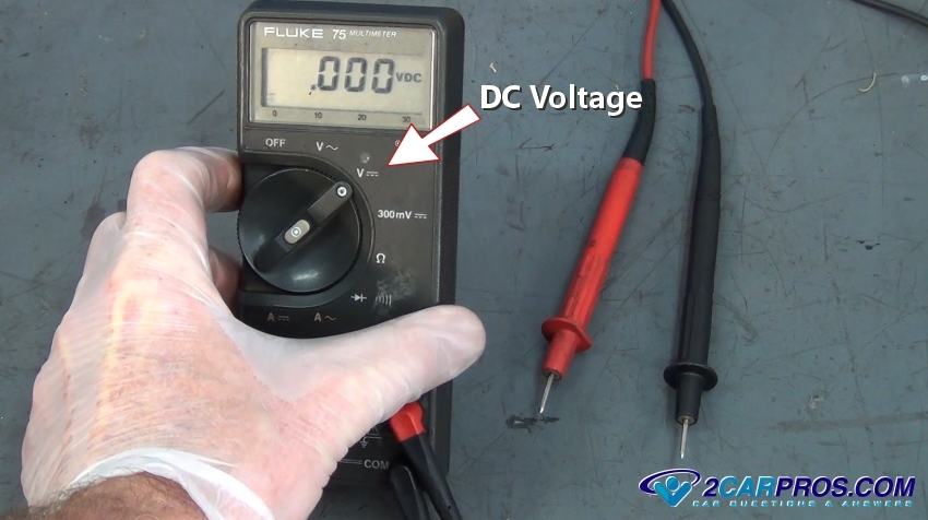
Locate the battery which is under the hood in most cases but some car's have them under the back seat or in the trunk. If you have a set of alligator clips that came with your meter you can change them out for the standard point probes which make testing easier but are not necessary. You can simply hold the test probes to each on of the battery terminals during the test.
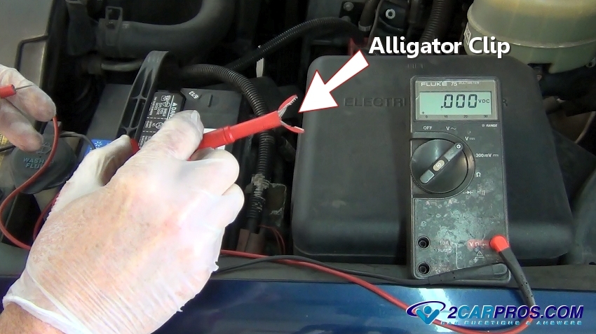
Identify both the negative (black) and positive (red) battery terminals. If both are either red or black reference the battery itself for markings depicting the polarity + or - . Next, attach the voltmeter leads or simply hold the leads onto the battery terminals.
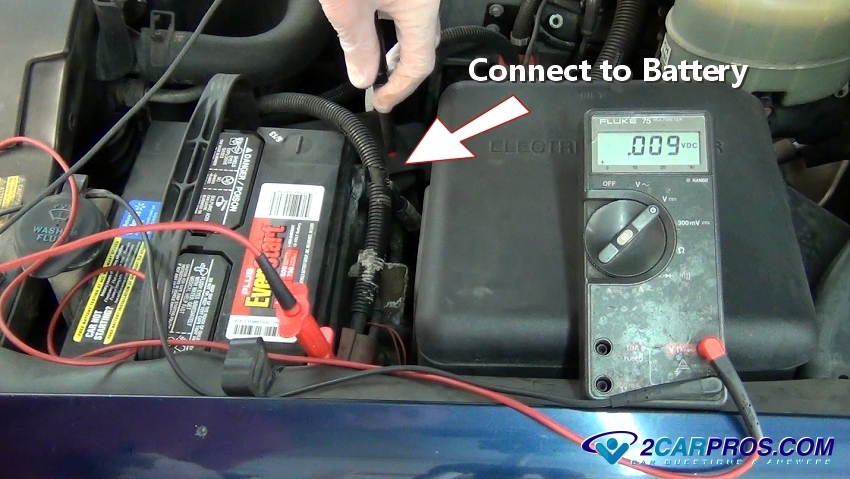
The voltmeter will then read the battery voltage @ about 12.2 to 12.6 volts. If the battery is down on charge these readings will be lower and can be anywhere from 6.5 to 10.8 volts. If so the battery will need to be load tested, charged or replaced before testing can begin.
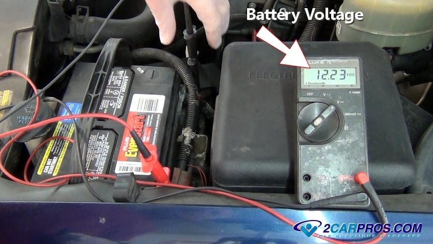
STEP 2: TESTING THE ALTERNATOR VOLTAGE OUTPUT
Have a helper start the engine and hold the RPM's just above idle at about 1500 and observe the meter. It should read between 13.6 and 15.8 volts depending on battery condition and state of charge. If the voltage on the meter stays the same or drops when the engine is started the alternator is not charging. You should then check the fuse panel for blown fuses and inspect the wires in the harness which lead to the alternator. If everything checks out the alternator is bad and needs replacing.

The next step in testing is to load test the alternator to see if it can hold up under heavy usage. While the voltmeter is still hooked up and the engine still at a raised RPM turn the headlights and air conditioner on. This will demand an electrical system load which will force the alternator to perform to its maximum output. If the voltage starts to drop the unit is weak and needs replacement.
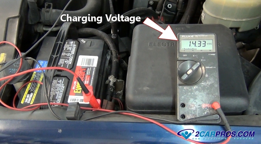
SPONSORED LINKS
STEP 3: DIODE TESTING
When the alternator diode pack fails it can leak AC voltage which can cause disruptions in the electrical system including causing premature battery failure. It can also cause other electrical components such as the radio and gauges to act strangely. To test for this condition switch the voltmeter to AC voltage with the engine at about 1200 RPM, the meter should read 0 volts. If voltage is present one or more diodes has failed and the alternator should be replaced.
Please watch the following video below to watch the test being performed by one of our mechanics. The following information pertains to all internal combustion engines vehicles.
ADDITIONAL TESTING WITHOUT A VOLTMETER
For this test you will need to wait until evening so you can see the headlight brightness which is best at night. Then turn the vehicle headlights on with the engine off and then observe the headlight brightness, then start the engine. The brightness level should momentarily fade as the engine cranks but then get brighter than when the engine was not running telling you the alternator is charging. If you still cant tell, you will need a voltmeter. This test will not work for LED headlights.
SYMPTOMS OF A CHARGING SYSTEM FAILURE
- Dead battery
- Battery warning light on
- Engine cranks over slowly followed by a loud clicking noise
- Engine stalls while driving
An alternator cannot sustain maximum output for long periods of time, it will overheat and fail. A shorted or old battery can cause premature failure of the charging system so it's a good idea to replace the battery at the same time as the alternator if it is three years or older. Avoid unnecessary sparks near the battery. This is to stop accidental ignition of hydrogen gases present inside the battery causing it to explode. This conditioner is typically present when you can smell sulfur causing hydrogen gases.

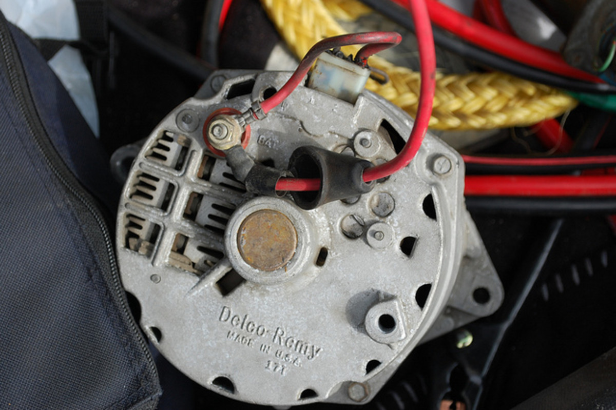
What Does a Condenser Do for an Alternator?

Alternators produce an electrical field that can interfere with radio reception. An alternator condenser corrects this problem. Automobile alternators are necessary to recharge the car battery and to run the car electrical systems without using the battery.
Alternator
An alternator converts the mechanical energy of the engine into electrical energy in the form of alternating current. It makes this conversion by spinning wire brushes at high speed near copper coils to create an electrical field. The electrical current the alternator produces is the discharge of this field.
Condenser
The word condenser has been replaced largely by the word capacitor when referring to the type of device used as an alternator condenser. A capacitor or condenser has no moving parts. It consists of an insulator connected to two conductors.
Alternator Condenser
Troubleshooting Alternator and Charging System Problems
Alternator condensers are seen mainly in older automobiles. Modern car radios are designed largely with a built-in shield against alternator-generated static. When a condenser is used, one of the leads connects to the alternator and one connects to ground. When a difference in voltage exists between the leads, a field is generated. Excess energy stores in the insulator, shielding the radio from the interference that would otherwise be
discharged.

Alternator problems and charging system problems can affect your vehicle in different ways. You may notice:
- your ALT or CHARGE indicator light comes on,
- your engine is hard to start and cranks slowly, or doesn't crank,
- your battery demands lots of water,
- your alternator makes noises,
- or your headlights suddenly go dim.
These and other problems may be caused by a fault in the charging system.
Before you start replacing components with the hope of fixing the problem, you need to make sure what component or components are causing you trouble. Often, it is possible to diagnose and solve the problem on your own using a few simple tests and tools.
The sooner you find out what is causing trouble, the better. You'll prevent a faulty component from ruining other parts in the system, making your repair more expensive.
This convenient troubleshooting guide will help you do find out what you need to know, using a few simple checks you can do at home using a test light or digital multimeter (DMM) and possibly a few other common tools.
It is a good idea to have on hand the vehicle repair manual (or a good aftermarket manual) for your particular car make and model. It will help you identify wires, specific components, and possibly suggest some specific tests recommended by your manufacturer.
If you want to test the condition of the system as a diagnostic starting point, do the tests described in the following section, "General Charging System Check."
However, if you need help for a specific problem with your charging system, for example an over-charge or under-charge condition, discharging battery, or noisy system, then skip over to the "Charging System Problems and Potential Causes" section.
Index
|
|---|
I. Common Symptoms of a Bad Alternator or Charging System
|
II. General Charging System Checks
|
III. Charging System Problems and Potential Causes
|
IV. Troubleshooting for Unusual Voltage System Drops
|

I. Common Symptoms of a Bad Alternator or Charging System
Indicator Light On
Usually, the first sign that your charging system is in trouble is a "battery," "ALT," or "CHARGE" warning light illuminating on your instrument panel while driving. It means that for some reason, the alternator has stopped charging the battery and your car is running on battery power. If the light illuminates only intermittently, it usually indicates worn-out or bad carbon brushes in the alternator. But remember that the light doesn't always mean there is a bad part; the light may be triggered by a sensor giving a wrong message.
Engine Cranks Slowly or Not at All
Engine Cranks Slowly or Not at All
When the battery is undercharged, the engine cranks slowly or doesn't crank at all. Go over the next section on "General Charging System Checks," and, if necessary, check the section "IV. Troubleshooting for Unusual Charging System Voltage Drops." further down in this article.
Battery Overheating and Using Too Much Water
An overcharged battery causes the battery to overheat. You find yourself adding water to the battery frequently. If the problem is not taken care of on time, it can ruin your battery. Besides going through the next section, make sure to check section IV below on "Troubleshooting for Unusual Charging System Voltage Drops"
Noises Under the Hood
Squealing, buzzing or grinding noises coming from the engine may be caused by bad alternator components, a loose or worn-out serpentine belt, or a faulty belt tensioner. See the "Checking for Alternator Noises" subsection further down in this article.
Dimming Lights
If you notice the headlights, instrument panel, or interior lights dimming, either your battery has a low charge, or there's one or more faulty diodes inside the alternator. Check your battery and see the "Alternator AC Voltage Leak Check" subsection further down in this article.

II. Six Tests for the Charging System in General
These series of charging system checks help diagnose the general condition of your charging system. They can help you confirm that you actually have a problem in your charging system and locate the source of the problem.
1. Make a Visual Inspection of the System
With the engine off, pop the hood open and visually inspect the different components of the charging system. Look for a worn out or loose drive belt, alternator connection problems, loose alternator mounting bolts, and corrosion and dirt around the battery case and cables.
When inspecting the drive belt, check for adjustment. If necessary, adjust the belt with the help of your car owner's manual or repair manual. Inspect the belt for signs of cracks, cuts, shiny spots, deterioration or other signs of wear or damage. Change the belt and belt tensioner at the manufacturer's recommended interval.
2. Check for Wiring Problems
Inspect the wires and connections at the back of the alternator, at the remote voltage regulator (if applicable), and at the battery. Look for corrosion at the connectors, damaged wires, and burned and missing insulation that might suggest an electrical short.
3. Do This if the Indicator Light Stays on, or Goes on and off
Follow the next steps:
- Start the engine and apply the emergency brakes. Set the transmission to Neutral (manual) or Park (automatic).
- Connect a voltmeter across the battery terminals.
- While watching the voltmeter display, start wiggling wires at the back of the alternator, the battery, and the remote voltage regulator (if there is one).
- If the voltage reading on the meter display goes up while wiggling one of the wires, you've found a bad electrical wire or connection.
Instead of using a voltmeter, you can have an assistant watch the indicator light on the instrument panel to see if it turns off as you wiggle various wires and connectors. Once the light turns off, you've found the problem connector or wire.
4. Check for Alternator Noises
Bad alternator bearings, rectifiers, rotor shaft, stator winding, slip rings, brushes and other parts inside the alternator with mechanical or electrical problems can become noisy.
4. Check for Alternator Noises
Bad alternator bearings, rectifiers, rotor shaft, stator winding, slip rings, brushes and other parts inside the alternator with mechanical or electrical problems can become noisy.
Here's a test you can do: Use a length of vacuum hose to listen for alternator noises. The hose will amplify the noise if it's coming from the alternator. But be very careful around moving parts while you do this test.
- Start the engine.
- Place one end of the hose against your ear and move the other end around different points of the alternator body.
- Listen for whining noises (this can indicate a bad diode or an over-charging condition), grinding (bad bearing), squealing, or other abnormal noise. If necessary, have your alternator checked.
5. Check for Under-Charging and Over-Charging
The next three tests are best done using a load tester, but you still can use your digital voltmeter. You do this by measuring system voltage while loading the system.
The next three tests are best done using a load tester, but you still can use your digital voltmeter. You do this by measuring system voltage while loading the system.
5a. First, measure battery base voltage to make sure you have a fully charged battery.
- Turn on the high beams for 10 seconds and then turn them off.
- Wait for two minutes
- Measure battery voltage across the battery posts with your DMM. You should get between 12.4 and 12.6V. This means your battery is fully charged. If you get a reading below 12.4V, charge the battery before continuing.
5b. Measure the Charging System's No-Load Voltage
- Ask an assistant to start the engine and hold engine speed at about 1500 RPM.
- Measure voltage across the battery with your DMM. You should get 0.5 to 2 volts higher than base voltage. If you are getting more than 2 volts above base voltage, most likely your alternator is over-charging the battery or the battery is faulty. Other potential problems are a faulty voltage regulator or a problem in the charging system wiring. As part of your wiring checks, see the section "Troubleshooting for Unusual Charging System Voltage Drops" below.
5c. Measure charging system load voltage with a high-current-condition system measurement.
- Ask an assistant to start the engine and hold engine speed at about 2000 RPM. Turn on all electrical accessories like A/C, blower motor, headlights, defroster, wipers. But don't turn on the heated windshield if your vehicle has one; alternator voltage may increase to over 100V and this can be unsafe.
- Take a voltage reading across the battery posts. Your reading should be at least 0.5 volts above base voltage for your system to keep up with electrical system demands. Otherwise, the charging system can't meet the demand and charge your battery. This fault could point to a faulty alternator or voltage regulator. Check the section "Troubleshooting for Unusual Charging System Voltage Drops" below to check for wiring problems that can lead to this condition.
- NOTE: these measurements correspond to an ambient temperature of about 70º F. The charging voltage will increase as temperature drops, and charging voltage will decrease as temperature goes up. So keep this in mind when making your measurements.
6. Check for Alternator AC Voltage Leak
Alternators use diodes to rectify alternating current produced by the alternator into direct current. When one or more diodes go bad, the alternator can cause all kinds of problems. AC voltage leak can cause your lights to dim and drain power from your battery, for example. Usually, you can detect this leak by measuring AC voltage across the battery posts using a digital multimeter.
Alternators use diodes to rectify alternating current produced by the alternator into direct current. When one or more diodes go bad, the alternator can cause all kinds of problems. AC voltage leak can cause your lights to dim and drain power from your battery, for example. Usually, you can detect this leak by measuring AC voltage across the battery posts using a digital multimeter.
- Start and let the engine idle.
- Set the parking brake and your transmission to Park (automatic) or Neutral (manual).
- Set your meter to a low AC voltage range and take your measurement.
- If you detect even a small amount of AC voltage, replace the alternator.
Once you've determined the condition of the system, you can go over the next section to zero in on the potential problem(s) that may be causing the condition of the charging system.

III. Charging System Problems and Potential Causes
To speed up your diagnosis and repair, look up the system condition that most resembles your problem and go over the potential causes described under that condition. Some checks or tests may be suggested as appropriate.
1. If the Battery Seems to Stay Undercharged
You have already charged your battery a couple of times and you just found out the battery is undercharged again. Before you blame your battery, or the alternator, here are some preliminary checks you may want to do.
a) Check the drive belt or serpentine belt, especially if you haven't replaced it in the last five years. Make sure the belt has the proper tension. Look for signs of wear or damage like cuts, shiny spots, missing chunks. Today serpentine belts don't show signs of wear, even if they need to be replaced. Use a belt wear indicator or check your maintenance schedule for the replacement interval suggested by your car manufacturer. You may find the schedule in your car owner's manual or your repair manual.
b) Along with the drive belt, check the belt tensioner as well. Make sure it turns freely and is noise-free. Car manufacturers recommend replacing the tensioner at the same time you replace the drive belt.
c) Make sure your battery connections are tight and clean. However, just because the terminals look clean, it doesn't mean they are tight and in good condition. Look for damage to the cable and the terminal itself that may prevent proper electrical current flow.
d) Check your battery yourself, or take it to your local auto parts store. Many of these stores will test your battery for free.
e) There's a parasitic battery drain stealing power from your battery.
- A quick test is to connect a test light in series between the positive battery cable and the positive battery post. If the test light comes on, there is an electrical drain in one of the systems.
- First, unplug the alternator electrical connector. If the test light goes out, the alternator is causing the drain. If not, locate the parasitic drain.
f) Don't overlook the starter motor: a failing starter motor may draw excessive current during operation, draining battery power. If necessary, have your starter motor or starting system tested.
2. If the System Seems to Be Over-Charging
Besides test results, another potential sign that your battery is being overcharged is that your battery terminals keep accumulating corrosion.
Here are some checks you want to do:
2. If the System Seems to Be Over-Charging
Besides test results, another potential sign that your battery is being overcharged is that your battery terminals keep accumulating corrosion.
Here are some checks you want to do:
- Make sure that all the connections to the alternator, remote voltage regulator (if applicable) and battery are clean, tight and in good condition.
- Check your battery or have it tested at your local auto parts store. A bad battery cell can cause the alternator to over-charge the good battery cells.
- Check for a bad alternator voltage regulator and circuit. Consult your vehicle repair manual, if necessary.
- Make sure you have good ground connections at the alternator (alternator case) and voltage regulator, especially if your vehicle uses a remote voltage regulator. Grounds should be free of rust, and the alternator and remote voltage regulator mounting bolts should be clean and tight.
- Check the alternator rectifier or have your alternator checked at the auto parts store.
- Also, conduct the tests described in the Troubleshooting for Unusual Charging System Voltage Drops below.
3. If the Alternator Is Not Charging the Battery
When your tests point to an under-charge or no-charging condition:
When your tests point to an under-charge or no-charging condition:
- Make sure the drive belt is not loose or worn out.
- If necessary, borrow a good battery just to operate the engine and confirm that your drive belt and belt tensioner are operating properly.
- Manually check the belt tensioner for proper operation. Make sure the tensioner pulley turns freely and without noise. Check it for damage.
- Manually turn the alternator pulley and make sure it turns without problem. If one of the bearings has seized, it won't allow the alternator to turn freely.
- Check that the connections at the battery, alternator, and remote voltage regulator are clean and tight.
- Check for a blown fuse or fusible link. Consult your vehicle repair manual, if necessary, to locate the alternator fuse or fusible link.
- Do the tests described in the section "Troubleshooting for Unusual Charging System Voltage Drops" below.
4. If the Engine Makes Noises
Noise can be a sign of alternator problems when it comes from the charging system. The next check points will help you isolate the source of the noise.
Noise can be a sign of alternator problems when it comes from the charging system. The next check points will help you isolate the source of the noise.
- Check the drive belt or serpentine belt. Look for signs of wear or damage like cuts, shiny spots or missing chunks under the belt. A worn out belt can squeal during operation.
- Also, check the belt tensioner for proper operation and damage. It should rotate freely.
- Make sure the alternator is properly mounted. Loose mounting bolts can cause the alternator drive belt and drive pulley to become misaligned and noisy.
- Check the alternator for noises. See the General Charging System Checks section for a simple procedure for this.
5. If Lights Dim During Engine Operation
Most alternators use diodes inside a rectifier to turn Alternating Current (AC) into Direct Current (DC) for use by the system. When one or more diodes go bad, AC can leak into the electrical system. Sometimes you can notice this when the headlights, instrument panel lights and other interior lights dim during engine operation. To test your alternator for AC current leaks, see the Alternator AC Voltage Leak Check subsection in the previous section.
Most alternators use diodes inside a rectifier to turn Alternating Current (AC) into Direct Current (DC) for use by the system. When one or more diodes go bad, AC can leak into the electrical system. Sometimes you can notice this when the headlights, instrument panel lights and other interior lights dim during engine operation. To test your alternator for AC current leaks, see the Alternator AC Voltage Leak Check subsection in the previous section.

IV. Troubleshooting for Unusual Charging System Voltage Drops
A charging system voltage drop check can help you locate the source of an under-charge or over-charge condition due to problems in the wiring or connections between the battery and alternator.
1. Start the engine and let it idle. Apply the parking brake and set the transmission to Neutral (manual transmission) or Park (automatic transmission).
2. Turn on the high beams, AC, wipers, and other accessories to provide a system load. Have an assistant raise engine speed to about 1500 RPM. But if your vehicle is equipped with a heated windshield, don't turn it on; this can make alternator voltage go over 100 V. Since you'll be working around alternator connections, this could be dangerous.
3. With your voltmeter test leads, touch the positive battery post and the B+ terminal connector at the back of the alternator.
4. Check your meter display. You should get around 0.2V or less of voltage drop. Getting 0.3V or more can lead to an under-charge condition. Check the connections in that part of the circuit for a loose wire, corrosion at the connectors or wiring damage that may prevent proper current flow between the battery and alternator. Also, check the electrical connections at the back of the alternator and at the voltage regulator.
5. Now repeat the test, but this time, connect your meter leads between the battery negative post and the alternator case.
6. Check your meter display. Again, you should get a voltage reading around 0.05V. If you get 0.1V or more, there's something wrong. This can lead to an over-charging condition. Checking that part of the circuit, make sure the battery ground connection is good, clean and tight. Add a temporary ground connection from the battery to the chassis. If this removes the high voltage drop, check the engine to body grounds connections. They should be clean, tight and in good condition.
Watch the next video for a visual reference on voltage drop checks.
Alternator problems are not uncommon after a few years of operation. A typical alternator may last anywhere from 8 to 12 years. So don't be surprised to find your alternator going bad or the system developing problems after a few years of trouble-free operation, even if you have maintained your car well.
The key point here is to do the proper diagnostic as soon as possible, because a bad alternator can ruin an otherwise good battery, and other components as well, depending on the fault.
Once you determine that your alternator is bad, you have several options. You can replace it with an original one from your dealer, an aftermarket replacement, or a rebuilt unit. Aftermarket alternators are a good option and less expensive, and many of them are just as good as their OEM counterparts. And rebuilt alternators are not as bad either.
++++++++++++++++++++++++++++++++++++++++
Alternator secrets and modern car so do diode loop
++++++++++++++++++++++++++++++++++++++++
Tidak ada komentar:
Posting Komentar