

A power amplifier cannot deliver an output wave wider than its power supply voltage. When you reach the limit, increasing gain may sound louder but sound will be distorted and can even damage speakers .This simple clipping indicator circuit will announce with an LED that you have reached that limit.
Step 1: Circuit Diagram & Main Components

Q1 BC547NPN transistor
Q2 BC557PNP transistor
D1-D3 1N4148diode
note: If your amp V+ voltage is higher than 45v use BC546/BC556(up to 65v) or other higher voltage ones.
also increase R4 for a led current of 30mA. ( R=v/a )
Step 2: Q1: Emitter Follower

Step 3: Q2: Led Driver

Step 4: C1: Peak Hold

For longer "peak hold" time increase R3 up to 100K
Step 5: D1-D3 Voltage Drop

Example Clip in Automotive
XXX . XXX
Following the Automotive Fuel Injector Testing Procedure

The fuel injector is the main actuator in a modern fuel injection systems. It is responsible for supplying the engine with fuel for combustion. In order to obtain the near perfect air/fuel ratio in today’s engines, the injector must meter and deliver a precise amount of fuel into the intake runners. The correct fuel flow and spray pattern can only be achieved, over a long period of time, through a well-maintained injector. In modern OBD II systems, injectors are closely associated with misfire code problems. There are many reasons why an injector could cause a misfire code.
A shorted injector coil that draws too much current, a bad injector driver, an ECM that cuts pulsation to the injector due to an overheating problem to keep the engine cooler and clogged injectors are all possible conditions that will set those persistent misfire codes. In some cases, as in an overheating engine, the problem is not the injector itself but some other condition that causes the injector not to pulse and therefore create the misfire. The vast majority of fuel injectors are ground controlled. This means that of the two wires going to the injector one is held at steady 12 – 14 volts while the other lead is pulsed to ground by the ECM. This type of injector circuit is called negative trigger. There are, however, a few (European) manufacturers that have used positive or battery voltage trigger injector circuitry in the past. With positive injector trigger, the positive side is the one being triggered by the ECM.
The component of the ECM that triggers the injector is called the driver. Injector drivers fall into two categories, the saturation and the peak-and-hold type driver. The injector driver itself is nothing more than a high current transistor and its main function is to switch the injector on and off.
A good number of late model ECMs are using the more advanced microprocessors, with 32 bit processor systems on most of them. These computer systems are capable of shutting down the injector driver in the event of a short circuit, a severe misfire, or an overheating engine. The Cadillac Northstar 4.6L engine was one of the first systems to employ such an ECM. The system shuts down the injectors intermittently in the event of an overheating engine in order for it to work cooler and therefore protect the head gaskets. It is important to determine if the misfire or lack of injector pulse is the result of an ECM strategy to save the engine from damage or an actual malfunction.
The 1st point (inj. Turn-on) shows the ECM driver pulling the battery voltage to ground. This action turns the injector ON. The 2nd point in the waveform or the space between the two vertical lines gives us the injector pulse duration. In this case about 4.5 mS. Then 3rd point is the injector turn-off. The vertical lines at the injector turn-on and turn-off points, should be clean and well defined. These lines show the condition of the ECM’s internal driver transistor. The 4th point is the inductive kick. This relatively high voltage spike, resulting form the collapsing magnetic field around the injector coil, is the main indicator of the general condition of the coil itself. The voltage usually ranges between 55 and 90 volts, with 65 volts being the norm. A low voltage inductive kick is a sure indication of an electrical problem. As said before shorted injector coil windings or any resistance in the injector circuit will show up in the voltage waveform as a low voltage inductive kick.
Fig: Detailed analysis of a saturation type fuel injector waveform.
As a side note, always remember that in some systems this inductive kick is clipped off. This is done through an internal ECM diode at around 30 to 45 volts and does not indicate a defective injector. In such systems, the upper part of the spike is squared-off or flat, typical of a diode clipping action. The 5th and last point of interest is the injector-pinttle-closing hump. This hump is not present in all injector waveforms and with practice a determination can be made as to which systems do show it.
The closing hump is an indicator of injector mechanical condition. If it is placed too far up the position shown in fig. 2, then it is a good sign of a dirty or clogged injector. If it is too far down, then the injector valve spring is weak. With some experience a fair and accurate determination can be made saving time and money.INJECTOR DRIVERSThe saturation driver is the more common of the two types. This driver transistor usually works together with a high impedance injector. High impedance injectors take their name because of their higher internal resistance (usually form 12 to 20 Ohms). These injectors are mostly used in multi-port injection systems. There are cases, however, in which low impedance injectors are used in multi-port applications, but such cases are rare.

The peak-and-hold driver is almost always connected to a low impedance injectors. This name is given because of their low internal resistance (usually from 1 to 5 Ohms). The low impedance injector is mostly used in TBI applications and generally requires a higher amount current to operate.
Fig: Wave analysis of a dual trace waveform. In this case, both current and voltage are shown. Current waveform points are represented by numbers while voltage waveform points by letters.

The peak-and-hold injector gets its name from its waveform characteristic. The actual current peaks at a certain level (4 to 6 Amps) so as to open the injector and then levels off at about 1 Amp to keep the injector open. Point (1 – A) is the injector turn-on. This is the point at which the ECM driver transistor grounds the injector coil. At this point the voltage goes low (grounded) and the current slopes up to about 4-6 Amps. The ECM does this to quickly open the injector. It takes a lot more current to force an injector to open (break the inertia) than to leave it open. This type of injector is used mainly in TBI applications, with it being bigger and heavier. The current needed to break the injector pinttle inertia is generally higher, hence the higher peak-current level. Point ( B ) is the injector peak duration. Injector peak times should never fall bellow 1.5 mS. Injectors with shorted windings will tend to peak much faster due to the low impedance of the windings. A range of 1.5 to 3 mS is normal. Point (2 – C ) is the injector peak current/inductive voltage kick. At this point the peak phase ends and the injector driver transistor goes into the hold phase of the injector pulse. Peak current range from 4 to 6 Amps, with voltage values of around 60 to 90 volts. As in the saturation type injector, a lower inductive kick is an indication of a problem with the injector circuit or coil windings. Point (3 – D) is the injector-hold time.
The peak time plus the hold time is the actual ECM commanded injector open time. Both duration times are taken into account. Normal hold current is around 1 Amp. Point (4 – E) is the injector turn-off and turn-off inductive kick. Voltage values here should be in the same range as point C with a straight vertical line indicating good turn off ability by the driver. At this point the injector pulse is over. Therefore, as said before, ECM commanded injector pulse duration is from point 1 – A to 4 – E. However, this is not the actual physical open-time, which is the time between the two dark cursors. The reason is that the injector just does not simply opens at the moment the ECM commands it to. It takes roughly ¾ of the peak current to fully open the injector and this corresponds to the first current hump (first cursor). Point F (second cursor) is the injector-closing hump. This hump can only be seen on the voltage waveform. Therefore, in order to make a determination as to whether the injector is clogged (misfiring cylinder) the actual physical open time has to be taken into account. With this in mind, a dual trace waveform capture of both current and voltage is the first step to a thorough and sound injector diagnostic. The reason is that the physical injector opening shows only on the current waveform while the closing of it shows only on the voltage waveform. Since today’s clamp-on Amp probes have come a long way, this is not much of a problem. A complete scope hook-up can be done in 5 minutes or less.
CONDITIONS THAT AFFECT OPERATION
High impedance injectors in practical, real-life applications usually draw a current of around 950 mA to 1.2 Amps, while it is more common to see a low impedance injector draw as much as 6 Amps. Any automotive actuator is always affected by conditions that place excessive resistance in its particular circuit. A voltage feed relay with carbonized or eroded contacts, a rusted or deteriorated injector connector, damage at the injector wiring itself and an open injector driver at the ECM are all examples of excessive injector circuit resistance problems. The same can also be said about mechanical problems developing inside the injector itself. A clogged, binding or corroded injector pinttle will cause a severe misfire and engine performance will suffer.
XXX . XXX 4 zero UNDERSTANDING FUEL INJECTOR WAVEFORMS
FUEL injectors – Chapter 1
Language is the key to understanding what is happening around you. Imagine being in a foreign country but not knowing how to speak the language of that land. Now, imagine being given your task in this land, to gather data and then make an informed decision based on this information. Not very many of us are that adventurous, and would cringe at the thought of this situation. However, this is what many of us do everyday. Many modern automotive technicians approach a vehicle not understanding the language, or data, that the vehicle is communicating with. After checking systems and gathering data, the modern technician is going to make a decision on what is wrong with the vehicle. But if the information was not understood or misinterpreted altogether, then this decision might be incorrect. Now, imagine you are working on a modern vehicle and could understand the language that it is speaking. This language is electrical impulses, changing amplitude (voltage) over time. Just like learning to read a written language, letters join together to convey useful information. In this electrical language, changes in voltage will convey useful information. The question at hand is how does one obtain this information or analyze this information? The key to unlocking this electrical language is the oscilloscope.
An oscilloscope is a device that displays voltage amplitude over time, thus creating a visual display or graph that is commonly referred to as a wave-form. These electrical waveforms carry information or data that is needed in diagnosing a vehicle. Each of these waveforms contains unique information about the electrical circuits which affect the operation of the vehicle’s systems. But what do these electrical impulses have to communicate or tell you?
Let us examine a very common saturation style injector (Figure 1).
At first glance the wave form this injector makes looks like a very simple signal. However, an in depth analysis is required to understand what is actually occurring.
 For each part of the electrical change; voltage over time, will have a story to tell you. Let’s look at Figure 2 Part A on page 27. This is the open circuit voltage or source voltage. The reason this is referred to as an open circuit voltage is the circuit has not been completed. There is no current flowing through the injector circuit at this point. In Figure 2 Part B, the voltage drops abruptly when the PCM driver turns on, thus completing the injector circuit to ground. This voltage drop should come very close to ground. The initial voltage drop will depend on whether the electrical device used is a transistor or a MOSFET. If a transistor is used, the drop will be .7 volts to 1 volt. This is due to the resistance across the transistor’s gate. MOSFETs have less resistance across their gate causing less voltage drop, usually about .2 volt to .3 volt drop. The voltage drop is the voltage that is remaining in the circuit to push the current across the resistance of the PCM driver or gate (Figure 2 Part C). Once the power train control module (PCM) commands the injector driver closed, current starts to flow through the injector coil circuit. When current flows through a coil winding all of the current is used to create a magnetic field around the winding (Figure 3). This magnetic field build up is inductance.
The magnetic field is proportional to the inductance and the current, in other words, the larger the current the larger the magnetic inductance. As the magnetic field is building, the inductance offers resistance to the current flowing through the injector circuit. This is due to the magnetic field building, as the field builds it moves across the coil winding which induces voltage into the coil winding. This induced voltage frees electrons which gives resistance to current flowing through the coil. This resistance is called counter voltage. Anytime there is resistance in a circuit there will be a voltage drop proportional to the resistance. This voltage drop can be seen at the bottom of the injector waveform. This is what causes the slight rise at the bottom of the injector waveform.
magnetic inductance. As the magnetic field is building, the inductance offers resistance to the current flowing through the injector circuit. This is due to the magnetic field building, as the field builds it moves across the coil winding which induces voltage into the coil winding. This induced voltage frees electrons which gives resistance to current flowing through the coil. This resistance is called counter voltage. Anytime there is resistance in a circuit there will be a voltage drop proportional to the resistance. This voltage drop can be seen at the bottom of the injector waveform. This is what causes the slight rise at the bottom of the injector waveform. If the oscilloscope voltage setting is lowered to magnify the bottom of the injector waveform, the voltage drop of the waveform can be seen more clearly (Figure 4 Part A). Since the current flowing through the winding makes the resistance for the voltage drop it mirrors the injector waveform made with an inductive amperage clamp (Figure 4 Part B).
Once the PCM driver closes, current starts to flow through the circuit. The magnetic field builds until it becomes strong enough to overcome the mechanical spring pressure holding the injector pintle in the seated position. At this point the injector pintle starts to move away from the seat through the magnetic field (Figure 5). 
When a ferrous metal moves through a magnetic field it causes the magnetic field to flex or change, thus inducing voltage into the coil winding. This induction releases free electrons which impedes the flow of current in the injector winding circuit, in turn, this causes the current to diminish slightly, creating the hump in the waveform (Figure 4 Part C). This hump shows when the injector pintle opens and allows fuel to flow through the injector. Note: Not all injectors will show this hump. The current then continues to build until the waveform reaches its maximum current. This is set by source voltage and the resistance in the circuit.
The PCM then calculates the correct time and turns the injector driver off, opening the circuit (Figure 2 Part F). This creates an abrupt voltage rise. The voltage level will then pass the open circuit voltage until it is clipped at a critical point. Note: Some injectors do not clip the flyback voltage. The voltage rise is caused by the magnetic field that has been built around the injector coil winding. Once the circuit is opened and current stops flowing, the stored energy in the magnetic field falls across the winding causing voltage to be induced into the injector coil (Figure 2 Part G).
This induced voltage is called the fly back voltage. The flyback voltage is then clipped (Figure 2 Part G). This voltage level changes between manufactures and systems. The flyback voltage is adjusted for the injector design being used in the circuit. The flyback voltage is set for the electromagnetic coupling of the injector and the mechanical spring rate. The magnetic field around the injector winding is stored energy which is used to control the speed that the pintle is closing with. If the pintle is allowed to close too fast the pintle and seat will become pounded out and will begin to leak fuel. With a fast closing rate the pintle can also bounce causing extra fuel to be delivered to the engine. This extra fuel cannot be controlled accurately so the engineer must adjust the energy held within the flyback voltage to accurately control the closing rate of the injector.
This is done by using a zener diode across the PCM driver (transistor or MOSFET). See Figure 6.
As the magnetic field falls back into the injector winding the energy is allowed to loop through the circuit. This allows the current to diminish at a set rate. The lower the voltage is set by the zener diode, the more energy is allowed to loop through the circuit. If a diode were used rather than a zener diode, this would let the most energy allowed loop through the circuit.
A diode will allow the stored energy to loop until it reaches source voltage, in this case 12 volts. This would allow the injector the longest period of time to close. The higher the zener diode voltage, the shorter the period of time allowed for the injector to close. This is due to the energy looping through the circuit being cut off early by the voltage rating of the zener diode.
If a 65 volt zener diode is used, the energy that is looping through the circuit is stopped at 65 volts which is 53 volts sooner than a diode, that allows the energy to continue to loop through the circuit until it reaches 12 volts. So the energy from a higher rated zener diode will shut off the energy looping through the circuit sooner which allows a faster pintle closing rate. Likewise, the energy from a lower rated zener diode will allow the energy to loop longer which will cause a slower pintle closing rate. This rate is set by the zener diode voltage which is matched to the injector design.
 The delay in closing voltage can be seen in Figure 2 Part H on page 27. Once the Pintle starts to fall through the magnetic field, the pintle distorts the magnetic field causing voltage to be induced (Figure 7). This is what causes the injector closing bump in the waveform. Notice that when current is not flowing through the injector circuit the pintle movement induces a positive voltage (Figure 2 Part I). Note: Not all injectors will show this bump. The PCM commanded time is the time from “B” to “F”; however this is not the true injector opening time. The true injector opening time is from hump “D” to the closing bump “I” (Figure 2 Part J). In a good circuit this time from “D” to “I” will equal the PCM command time from “B” to “F” (Figure 2 Part E).
The first thing in understanding a language is to understand the characters that make up the language. Once you can understand what data is being transferred, you can use this to make diagnostic decisions. Now that we understand the data contained in a saturation injector waveform we can use this data to see what has failed within the circuit. What story will a bad injector waveform have to tell you?
FUEL injectors - Chapter 2
In the last chapter we explained a language made up of electrical impulses changing amplitude (voltage) over time. Each electrical change makes up the letters or symbols of this language. Individually the letters can not tell you very much, but when the letters are linked together they have a story to tell you. Just like evaluating an ancient language each character or symbol plays a very important roll in telling the whole story. If any character is missing or cannot be understood, a portion of the story is missing. This could change the story considerably depending on which part may be missing. It will be very important when evaluating waveforms that each letter or character is understood. This will enable you to have the complete story. When diagnosing a modern vehicle, one must have the complete story to arrive at the correct conclusion. Now let us check the letters of this language and link them together so they may tell you a story. We will analyze several saturation style injector waveforms that are bad (Figure 1 Part A). When the power train control module (PCM) turns on the injector driver, the voltage drops abruptly. Notice the initial voltage drop through the driver is elevated to 1.8 volts. (Figure 1 Part B). This is high and shows there is resistance in the ground circuit. As current flows, the voltage drop across the resistance rises to 7 volts. Notice the injector pintle opening hump is missing (Figure 1 Part C). The PCM then calculates the on-time of the injection pulse. At this time the PCM commands the injector driver off (Figure 1 Part D). The voltage has an abrupt rise which goes above the open circuit voltage and reaches 65 volts (Figure 1 Part E).
story. When diagnosing a modern vehicle, one must have the complete story to arrive at the correct conclusion. Now let us check the letters of this language and link them together so they may tell you a story. We will analyze several saturation style injector waveforms that are bad (Figure 1 Part A). When the power train control module (PCM) turns on the injector driver, the voltage drops abruptly. Notice the initial voltage drop through the driver is elevated to 1.8 volts. (Figure 1 Part B). This is high and shows there is resistance in the ground circuit. As current flows, the voltage drop across the resistance rises to 7 volts. Notice the injector pintle opening hump is missing (Figure 1 Part C). The PCM then calculates the on-time of the injection pulse. At this time the PCM commands the injector driver off (Figure 1 Part D). The voltage has an abrupt rise which goes above the open circuit voltage and reaches 65 volts (Figure 1 Part E). The flyback voltage from rise to fall is very close together. This is unlike a clipped flyback voltage where there is space between the rising and falling edge of the voltage. Since this injector waveform is a clipped signal at 65 volts, this shows there was not enough energy stored in the magnetic field. Since the current flowing through the injector winding makes the magnetic field, this indicates the current through the circuit is diminished.
As the voltage falls back to open circuit voltage there is no injector pintle closing bump (Figure 1 Part F). This injector never opened due to resistance on the ground side of the circuit.
To locate where the resistance is within the ground circuit, one must move the scope probe from the injector connector to the PCM connector. In Figure 2 this is the same circuit, but the probe has been moved to the PCM connector. This waveform shows that we are past the resistance, indicating the problem would be with the signal wire or a connection between the injector and PCM.
Let’s take a closer look at this injection waveform. The PCM commands the injector driver to close (Figure 2 Part A). Notice the initial voltage drop through the driver is 0 volts which indicates there is very low current flowing through the driver (Figure 2 Part B). The higher the current flow through the driver is, the higher the initial voltage drop occurs across the driver or gate. Once the current starts to flow through the circuit there is no counter voltage (Figure 2 Part C). In other words, across the injector on-time the voltage has no rise and stays at 0 volts. Since current flowing through the winding makes the counter voltage, this shows there is very low current flowing through the injector winding. Once the PCM calculates the on-time it commands the driver off. At this point the voltage has an abrupt rise (Figure 2 Part D). The voltage rises above open circuit to 65 volts. Again, notice how close together the rising and falling edges of the flyback voltage are. This indicates low current flow through the injector winding. As the voltage falls back into the open circuit voltage there is no injector closing pintle bump. This indicates the injector did not open.

Now let us look at another injector waveform that has some of the same traits as the injector waveform that we have just covered. In Figure 3 Part A the PCM commands the injector driver on. The initial voltage drop through the driver is 0 volts (Figure 3 Part B). This indicates there is very low current flowing through the circuit. As current starts flowing through the injector winding there is no counter voltage rise (Figure 3 Part C). This indicates very low current flow.
The PCM then commands the injector driver off, creating an abrupt voltage rise which rises above open circuit voltage (Figure 3 Part D). The flyback voltage only reaches 60 volts which is 5 volts below the zener diode voltage for this circuit (Figure 3 Part E). This shows the magnetic field is very weak. It does not even have enough energy to reach the zener voltage at 65 volts. As the flyback voltage falls back to open circuit voltage there is no injector pintle closing bump. This shows the magnetic field never built strong enough to overcome the pintle spring, so, the injector never opened. The scope probe was located at the injector connector and there is not a voltage drop indicated on the control side of the circuit. The problem would be up stream of the probe connection which would indicate the connection, injector winding, or power to the injector would have a resistance problem.

Before disturbing the injector connector by unplugging it, move the scope probe to the power (voltage) side of the injector connector. Figure 4 shows the power side (CH2) and control side (CH1) of this injector circuit. Now you can see the problem more clearly. Ch2, the red trace, is the 12 volt feed circuit to the injector. Notice the open circuit voltage on both power and control is equal. When a circuit is open no current is flowing, thus, no voltage drop can occur (Figure 4 Part A). Once the PCM commands the injector driver to close, the current starts to flow. Now the power side shows the voltage drop clearly (Figure 4 Part B).
To find where the resistance would be within the power circuit one would move the scope probe up stream until there was no voltage drop. Once the scope probe has moved past the resistance, it will no longer show the voltage drop. This would indicate the resistance would lie between the injector connector and the point at which the voltage drop stopped. Note: On some systems a voltage drop on the power side is normal. If a dropping resistor is engineered in the injector circuit this would be normal (Check the correct wiring diagram for the vehicle). However, if the injector is not opening there is still a current problem within the circuit.
Now check how large the voltage drop is. If the dropping resistor has too much resistance or a connector is dropping voltage, the current to the injector will not be enough to properly work the injector. As you can see, when the letters of the language are linked together and can be understood, they are able to tell a story about what has gone wrong within a circuit.
FUEL injectors - Chapter 3

In the last chapter we looked at an electrical language where changes in voltage over time show you how to trouble shoot a circuit. When you can understand the secret unseen language of the computer you can tell a great deal about the circuit. In the days of old, to acquire information from a person who was unwilling to talk, kings would put the individual on the rack and then tighten the screw. At this point the unwilling individual could be persuaded to talk. The question at hand is “how can a technician persuade electrical waveforms to talk and give you the information that you need to repair modern vehicles”?
The modern day rack is the oscilloscope. The modern technician will put the wave-forms on the oscilloscope and turn the knobs. Then the un-willing electrical waveforms will not only talk but will tell you a story about the circuit. One must still understand the language of the electron. The oscilloscope is the key to entering the swift silent unseen world of the electron. Once the electrical impulse is put on the oscilloscope and the technician adjusts the voltage and time base so the portion of the waveform to be analyzed can be seen clearly it will be easy to make these waveforms talk.

Now let’s turn the oscilloscope knob on a bad injector wave-form. We will analyze two injector waveforms (Figure 1 and Figure 2). At first glance both of these waveforms look good. However, one of these has a problem. Can you see it? Let’s analyze Figure 1 Part A and Figure 2 Part A. The power train control module (PCM) commands the injector drive on. The voltage has an abrupt change and falls near ground on both patterns (Figure 1 Part B and Figure 2 Part B). Current begins to flow through the injector winding and counter voltage begins to rise off ground (Figure 1 Part C and Figure 2 Part C).
Notice the counter voltage on Figure 1 Part C has more counter voltage rise than in Figure 2 Part C. The PCM then calculates the correct on-time and commands the injector driver off. This causes an abrupt rise in the voltage (Figure 1 Part D and Figure 2 Part D). The voltage rises past the open circuit and peaks out at the point it is clipped at 65 volts (Figure 1 Part E and Figure 2 Part E). Notice that on Figure 1 Part E the flyback voltage between the rising edge and the falling edge has more space between them than Figure 2 Part E. This is an indication that the magnetic field has more energy stored in Figure 1. Since the magnetic field is built by the current flowing through the winding, this shows that Figure 2 has a resistance problem within the injector circuit. As the voltage falls back into the open circuit voltage, you can see the injector pintle closing bump. Notice that Figure 1 Part F has a longer closing rate by 2.5 microseconds than Figure 2 Part F. This is because the magnetic field has more energy and can control the pintle closing rate.

Now let’s magnify the bottom counter voltage and analyze these wave-forms (Figure 3 and Figure 4). At first glance these wave-forms look a lot different. They are not like Figure 1 and Figure 2 where the appearance seems very similar. In Figure 3 Part A and Figure 4 Part A, the PCM commands the injector driver closed. This creates an abrupt fall in the voltage. The initial voltage drop comes very close to ground (Figure 1 Part B and Figure 2 Part B).
The current starts to flow through the injector winding making counter voltage which causes the voltage drop at the bottom of the waveform. Note: Figure 3 voltage setting is at 2 volts for the chart while Figure 4 voltage setting is at .5 volts for the chart. In Figure 3 Part C we can see the injector pintle open, in Figure 4 Part C we can also see the injector pintle open, however, the opening time is delayed by 1.9ms. The counter voltage difference from Figure 3 to Figure 4 is .65 volts. Since the counter voltage mirrors current flow, Figure 4 has considerably lower current flowing through the injector circuit. Due to the diminished current flowing through Figure 4 the magnetic field takes longer to build. This delay in the magnetic field causes the pintle spring to keep the pintle seated longer. The magnetic field has to have more energy than the mechanical force of the spring to overcome it and open the injector pintle. The resistance within Figure 4 is not in the control side of the circuit. You can clearly see the voltage drop on the ground side is good. You would need to check the power side of the injector, the injector connector and the injector coil winding to find the problem.
In this example the problem is high resistance in the injector coil winding which causes the opening and closing delay. The problem is very hard to see until you magnify the counter voltage in the injector waveform. At first glance one might not see a difference between Figure 1 and Figure 2, or cylinder 1 and cylinder 2, but upon closer inspection we can see that there is a delay of 2.15ms. In Figure 1 the actual injector opening time is 32us or 3.2ms. In Figure 2 the actual injector opening time is 11us or 1.1ms. This is one third the fuel delivery and would cause a lean misfire and rough idle complaint that can be easily overlooked.
 Now let us look at another injector waveform that could give a rough running complaint. In Figure 5 Part A, the PCM commands the injector driver to turn on. The voltage has an abrupt drop towards ground. The initial voltage drop is 1.9 volts (Figure 5 Part B) which is high for a MOSFET style driver. As current starts flowing through the circuit the counter voltage does not have very much change; only about .1 of a volt. This is low and shows the magnetic field is not moving through as many injector coil windings. When we look across the counter voltage the injector pintle opening hump is very small (Figure 5 Part C).
The PCM then calculates the on-time and turns the injector driver off. This creates an abrupt rise in voltage. This rise passes the open circuit voltage and reaches a flyback voltage of 25 volts. This is very low for the circuit that has as a 62 volt zener diode setting the voltage clamp level. Also notice the rising and falling edges of the flyback voltage have no space between them. This indicates there is very low energy stored in the magnetic field. Now the flyback voltage falls back into the open circuit voltage, but there is no sign of the injector pintle closing bump.

Now let us look at the same problem using an inductive amp clamp (Figure 7 Part A). The injector driver turns on and completes the circuit. Current starts to flow through the injector winding. Notice that the transition from 0 volts to 1.4 volts is very abrupt. This shows there is very little counter voltage. This injector is shorted in the coil windings. A good injector will ohm at 16.5 ohms, but this shorted injector ohms at 7.3 ohms which is less than half of the windings that would normally be completed. In Figure 6 Part B the initial drop in the voltage waveform is 1.7 volts, which is quite high. The reason for the elevated voltage is resistance which is in the injector driver. The driver itself is not bad but due to the increased current flowing through the driver, or gate, it will offer more resistance to the current flowing through it. Much like a freeway, as traffic increases on a Monday morning the traffic starts to back up. The more traffic increases the greater the back up will be.
Now let us check the counter voltage which has very little rise. This is due to the decrease in the injector winding count. As the magnetic field builds up there are only one half of the windings that are completed. This cannot offer as much counter electromotive force to impede the current flowing through the circuit. The PCM then commands the driver off. The magnetic field falls back through the injector windings which induces voltage in these windings. Since there are fewer windings to induce voltage in, the flyback voltage is diminished. The injector pintle closing bump is not present due to the reduced magnetic field. Since the magnetic field is weakened it cannot be flexed as much, thus, less induction occurs which in turn creates no closing bump. One thing to notice is that the current flowing through the injector is twice the amount as in a good injector. One might think since there is more current flow the magnetic field will be larger. If we move current through a wire, a magnetic field will surround this wire.
The more current that flows through this wire the larger the magnetic lines of force become. However, in a winding or coil the more turns that are made around a core, the more magnetic amplification will occur. When a coil has fewer turns, this creates less amplification or a weaker magnetic field. It is possible to have an injector shorted with current flowing as high as 9 amps, but the magnetic field is so weak it cannot overcome the mechanical pintle spring to open the injector.
The waveforms are silent and unwilling to talk, but if you put them on you rack and twist the knob, they will tell you a story and what a story they have!
How Electronic Fuel Injector Works
- 1. Fuel Distributor CamshaftAccumulator
- 2. A fuel pump mounted near fuel tank sends fuel to accumulator at the pressure of 100psi Fuel passes through fuel distributor
- 3. Let’s Know About The Loopholes Of Mechanically Controlled Injectors
- 4. Less Power Output : Mechanical System can’t provide high-pressure fuel to engine
- 5. 2nd cause of less power generation :The Carbon Build Up on intake blocks the airflow into the cylinder ..
- 6. Burn holes in catalytic converter: Due to disturbance in fuel flow ,the carbon built up on intake increases day by day and this built-up causes holes in catalytic converter
- 7. Produces high percentage of Emission due to mechanical injectors
- 8. Expensive :
- 9. Electronic Fuel Injector
- 10. Electronic Injector System also possess springs Injectors opened By Electromagnet system The ECU determine the duration of getting open and close of injectors
- 11. Air Pressure Air Density
- 12. Air -Fuel pressure Coolant Temperature
- 13. Timing Speed
- 14. Is there any difference between Mechanical and electronic injectors..???
- 15. Yes ………..Electronic injectors are controlled by complex- microprocessor unit or a miniature computer But Mechanical System depends on the data from airflow sensor alone
the process EFI :
When tuned correctly, large gains can be made in detection accuracy. The chip that's responsible for the conditioning of the knock sensor output makes the "Knock Volts" parameter much different than what we're used to with the S1 AEM. Below are some of my findings about knock frequency, sensor type and location, signal conditioning, and system setup.
First, here's a brief background about engine knock. On the compression stroke, a mixture of fuel and air in the cylinder is compressed and it's temperature rises. (Boyle's Law) Between 40-10° BTDC the ecu will command ignition of this mixture and a controlled burn moving out from the spark plug will start to release heat, increasing pressure even faster. If ignition timing was right, cylinder pressure should peak right around 15° ATDC to get the most mechanical work out of the burned fuel. At that point, the flame has swept across most of the cylinder but only about half of the energy has been released. At a certain temperature for a given fuel, the mixture will autoignite (knock), which is essentially a bomb going off in the cylinder causing an extreme pressure spike. Although pressure may peak around 15° ATDC (or well before or after depending on ignition timing and burn rate), temperature is still increasing because of the burning fuel, and there's still a large amount of energy waiting to be released. It's in the 0-50° ATDC region that knock will occur. Generally, knock at an earlier crank angle will be more intense since there is more fuel available to spontaneously combust. Combustion chamber shape will have an effect on required timing advance. Less timing advance is needed for a small displacement pentroof combustion chamber. More timing advance is needed for a large displacement wedge combustion chamber. This has an effect on propensity to knock due to the amount of time the air and fuel mixture has to heat up. The faster burning design being less knock prone. A term that I've often seen associated with knock is pre-igniton. Pre-ignition is the ignition of the mixture before the spark plug fires and is caused by hot spots in the cylinder. Pre-ignition will almost certainly lead to knock. Sustained, severe knock will break ring lands, blow head gaskets, and melt holes in your pistons. The heaviest hand in reacting to spark knock is ignition timing retard since this variable will have a drastic effect on cylinder pressure and temperature. Increasing fuel will also absorb more heat, so a combination of these are what we implement to combat knock. For more on this subject, check out chapter 9 of Heywood's book, Internal Combustion Engine Fundamentals.
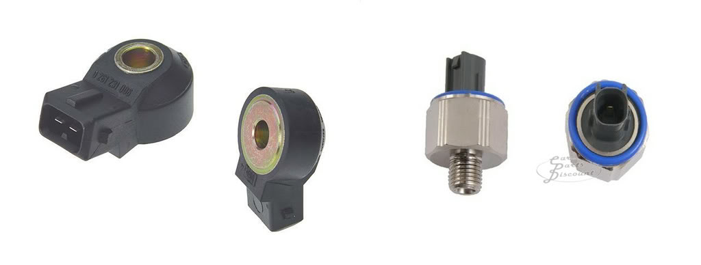
There is an important distinction with acoustic knock sensors. There are resonant type, like what come on my Toyota 2JZ engine, and flat response type. Resonant sensors are nice because the frequency filtering is done mechanically and this can save money on the ECU side by not requiring electronic filtering. They are tuned for a particular engine, though. Their output is like a bandpass filter, boosting a small range of frequencies and attenuating all others. Flat response sensors can be used on any engine and give OEM calibrators the ability to use much more complex knock detection strategies. Their output doesn't boost or attenuate any frequencies so you get a true representation of the sounds coming from the engine. Because the cost of the electronics has come down, flat response sensors have become a lot more common. Voltage output of resonant sensors is significantly higher than flat ones but you can set either type to work in the AEM software. Pictured below is a flat and a resonant response sensor. In my opinion, to get the most out of the AEM S2, you will want to switch to flat response sensors. I'll discuss this later.
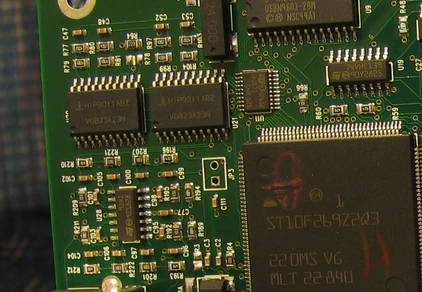
The S2 AEM uses the Intersil HIP9011 Knock IC. This chip has been around since the mid 1990s, but you'll still find it in a lot of the top aftermarket ecus to this day. The datasheet on this chip details it's design and operation.http://www.intersil.com/content/dam/Intersil/documents/fn43/fn4367.pdf You may also come across the Texas Instruments TPIC8101, which is a clone of the HIP9011. On the AEM main board, there are two of these ICs and I can see traces going to both input channels on each chip. I don't know the purpose of this since each chip has two channel inputs and all the S2 pinouts show only 2 knock sensor inputs. It would be very interesting to hear from an AEM engineer about what strategy they're employing with two of these chips...
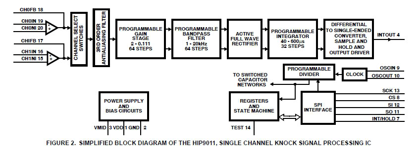
The block diagram below outlines each stage of signal processing in the HIP9011. In the software, we have control over the gain, bandpass filter frequency, and integrator time constant.
What we don't have control over is the knock window. The integration period (knock window) is controlled by the main CPU and is usually based off of crank degrees relative to TDC of each cylinder. I'm not 100% sure what AEM is using to trigger the time and length of this integration period. AEM, please let us know! Pictured below is a trace of the knock sensor signal, integration command from the CPU, and integrator output from the HIP9011.
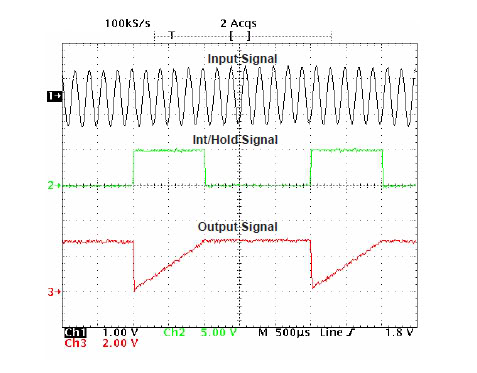
What we see here is a digital signal (high or low) from the CPU to the INT/HOLD pin on the HIP9011 chip. When this signal goes high, the integrator resets to .125V and begins ramping up from there. If, for example, the integration period is 50°, at 3000rpm, this period would be 2.77ms. Over that period, output from the knock sensor is processed by the op-amp, BP filter, and gain stages. These parts, along with the integrator time constant option, determine how quickly the integrator level rises. At the end of the integration period, the command to the INT/HOLD pin goes low and the chip will output the integrated voltage level at the INTOUT pin. This is what the CPU reads as the energy level for that last combustion event. This voltage level is held until the next power stroke comes along and it all starts over. The sharp pulse from a knock event will cause a corresponding sharp rise in the integrator and you'll see this as a higher voltage level over non-knocking cycles.
For reference, some other knock detection strategies look at crankshaft acceleration with a high resolution crank trigger, or even ion sensing at the spark plug on some high end cars. More advanced acoustic detection methods use digital signal processing, handled completely within the main CPU, and look at multiple frequencies and even the characteristic descending pitch signature of a knock event. The analog bandpass filtered, gated, rectified, and integrated scheme that AEM uses with the S2 isn't cutting edge, but it's served as a OEM standard for many years and still does a hell of a job. Some of the ECUs in LeMans and other high profile racing series still utilize this same chip/strategy for knock detection.
Engines produce all sorts of noise across the entire frequency spectrum. Accurate detection gets more difficult as rpm rises due to increasing noise levels. Reducing this background noise starts with the bandpass filter and is further reduced by the knock window. There is a formula that predicts the knock frequency based on bore size. It is: Knock Frequency = 900/(pi * 0.5 * bore in mm) This works really well, but there can be variances between engines by several hundred hertz +/- depending on all sorts of things. We have 64 choices of frequency from 1-20kHz in the software. If you get it right, the system will be able to distinguish between incipient and severe knock. Select a frequency above or below the optimal point and detection will be less accurate. Background noise will be a much larger part of the sample and any knock will be attenuated, seriously decreasing the knock (signal) to background (noise) ratio. You can use the calculated frequency, which will get you close, but you're better off finding it empirically through testing of your knock sensor on your particular engine. This will ensure you get the best signal to noise ratio and, therefore, the most effective knock detection. For the 2JZ engine, this calculated knock frequency is around 6.7kHz, but I've found that the fundamental frequency is closer to 6.4kHz for my motor. There are also ringing frequencies which you might choose if you have a particularly noisy engine. These will be less consistent throughout all operating conditions though, so I believe looking at the fundamental frequency is the best choice. To find it, you simply have to plug your knock sensor into the mic input on your laptop and record your motor while inducing light knock. Set the mic input level so you aren't clipping it at redline. I use a program called Goldwave to produce the recordings and another called Spectrogram to see the frequency content of the recording. It is critical that you record the knock sensor you will be using with the EMS and that it's mounted in the stock location(s). Sensor placement is extremely important so don't just find a spare sensor and bolt it into a free spot on the block! The procedures below assume you are starting with a safe and decent running tune. If you have no experience tuning, DON'T ATTEMPT ANY OF THIS!! Take your car to a tuner.
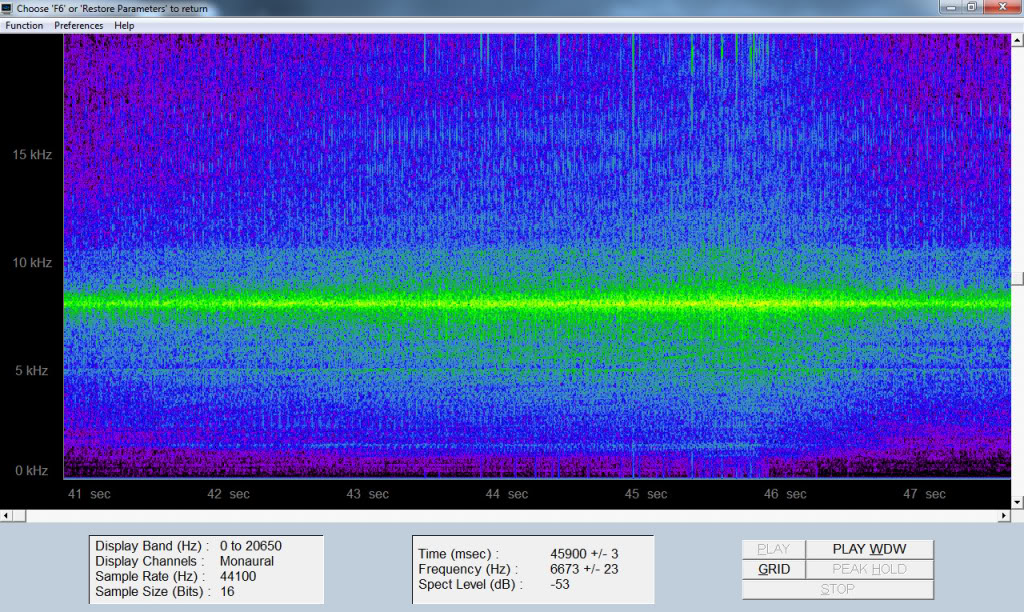
I decided to switch the knock sensors on my 2JZ engine from resonant to flat, so what you see below are recordings from a Bosch flat response sensor. I'll talk about why I switched a little later. There is no danger to your engine with brief, light load knock so this is where you want to start gathering data. I wanted to isolate only one knocking cylinder and keep all the others out of knock. The 2JZ has a front and rear knock sensor, so I plugged the front one into my laptop mic input and drove cylinder 1 into light knock. To do this, I varied the two tables, Injector 1 Trim and Coil 1 Ign Trim, leaning a/f and adding timing only at 3200rpm. I recorded several tests, adding a couple of degrees and removing a couple % fuel each time then listened and looked at the recording after each. It was around +15° and 10% lean before I saw any knock. I simply drove at about 25% throttle in 2nd or 3rd gear up to 3200rpm then let off. Below is what light load knock looks like in Spectrogram.
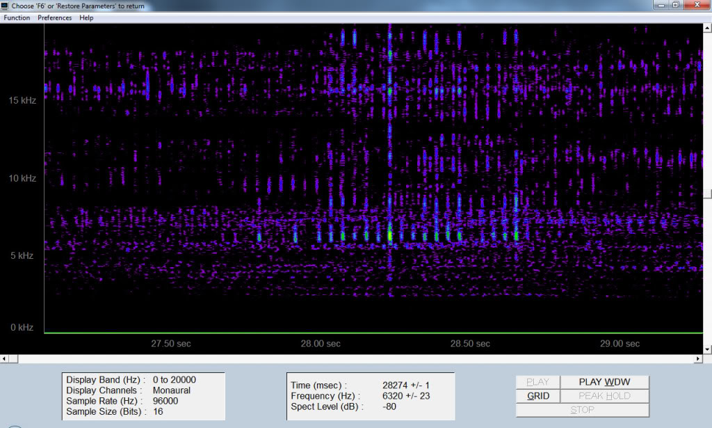
What you see are yellow dots centered right around 6.3kHz. 6.37kHz is what I selected in the software for Knock Frequency. Knock may sounds kind of like a bird chirping. When slowed down to about 1/10th speed, it'll sound like hitting an empty tin can with a stick. It's a very sharp pop and easy to identify. You'll see it as vertical lines in the spectrogram. The lowest frequency is the fundamental and the higher ones are the ringing frequencies. The fundamental will correspond most closely with knock intensity and it will be a lot more consistent than the ringing ones.
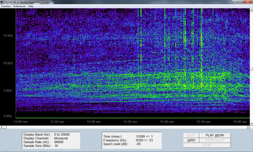
I also did WOT tests by removing 4° from all cylinders except #1. I crept up one degree at a time, taking recordings for each pull. After each pull, I reviewed the recording to listen and see if there was any knock. If your motor is turbocharged, do this at the lowest possible boost.
Once you have the frequency set, you can then start to take logs and set the gain and integrator time constant. These two options have a large effect on the Knock Volts channel. Gain is very easy to understand, it's just like the volume knob on a radio. Since the output of flat response sensors is so low, you will likely need to set this to the highest value of 2. Resonant sensors will probably need a 0.1 to 0.5 stetting.
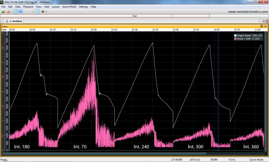
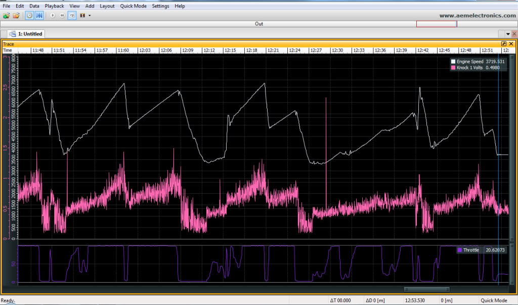
The integrator time constant functions as an output signal attenuator. A shorter integrator time constant will cause a steeper rise in the integrator voltage and, therefore, a higher voltage at the INTOUT pin. A longer integrator time constant will produce a lower output voltage. With flat sensors, a Knock Integrator value of 150-200 and a gain of 2 seems to give excellent results. When logging Knock 1/2 Volts, you'll want the highest level, at redline, to be somewhere around 1-1.25v range. What I've seen with an integrator time constant of 200 or higher is that a knock event will not stick out as much over the noise floor. If it's below 100, the knock free background noise will cause Knock Volts to reach over 3-4v and our range is only up to 5v. With too short a time constant, even light knock would send the knock channel to the max of 5v and there would be no way to tell how severe the knock actually was. Different engines might want slightly different values. I'd recommend changing gain and leaving the integrator option around 180 if possible. The pic below shows Knock 1 Volts output with a gain of 2, freq of 6.37, and various Knock Integrator values.
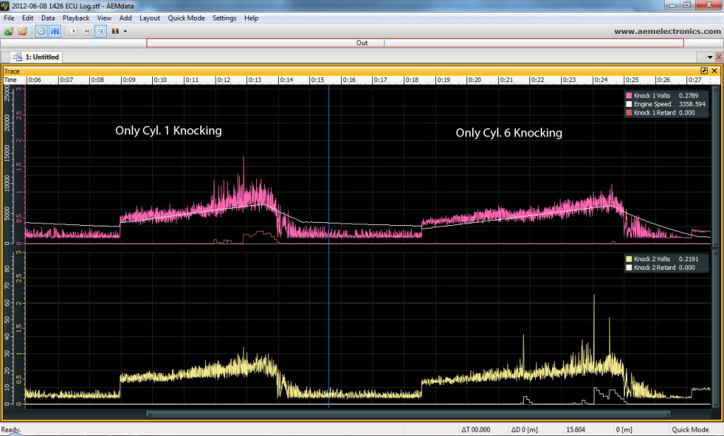
Pictured below is the logged data I got with light knock in only cylinder 1.
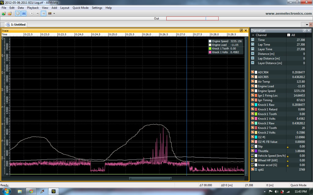
Here you can see knock being induced at WOT for cylinder 1 and 6 and corrective action taking place. As you can see, there is great signal to noise even at high rpm. Once you've decided on the frequency, gain, and integrator values, you can use the Knock Volts level you get from a knock free WOT pull to set your Knock Sensor Cal table.
I recently went to a track day and could see knock activity increasing as engine temperatures increased. Also, some burst knock with quick throttle application. Having logging and excellent knock detection allows you to refine your map for situations beyond what you're exposed to on the dyno. Accel fuel, ignition map, and ignition trim tables were modified based on this data.
Choosing the right corrective action will depend on the signal levels you're getting from Knock Volts. You might see incipient knock of .5v above the base and want to pull a degree or two. Severe Knock might be 1.5v or more above the base. The max timing retard I'd recommend is 10°, so you'd probably want to set the Knock Retard/Volt option to 5 or 6. 2-3% would be a decent setting for Knock %Rich/Volt with a max of 8%. Knock restore can be in the 50-100ms range. These settings may evolve as you gather more data over time.
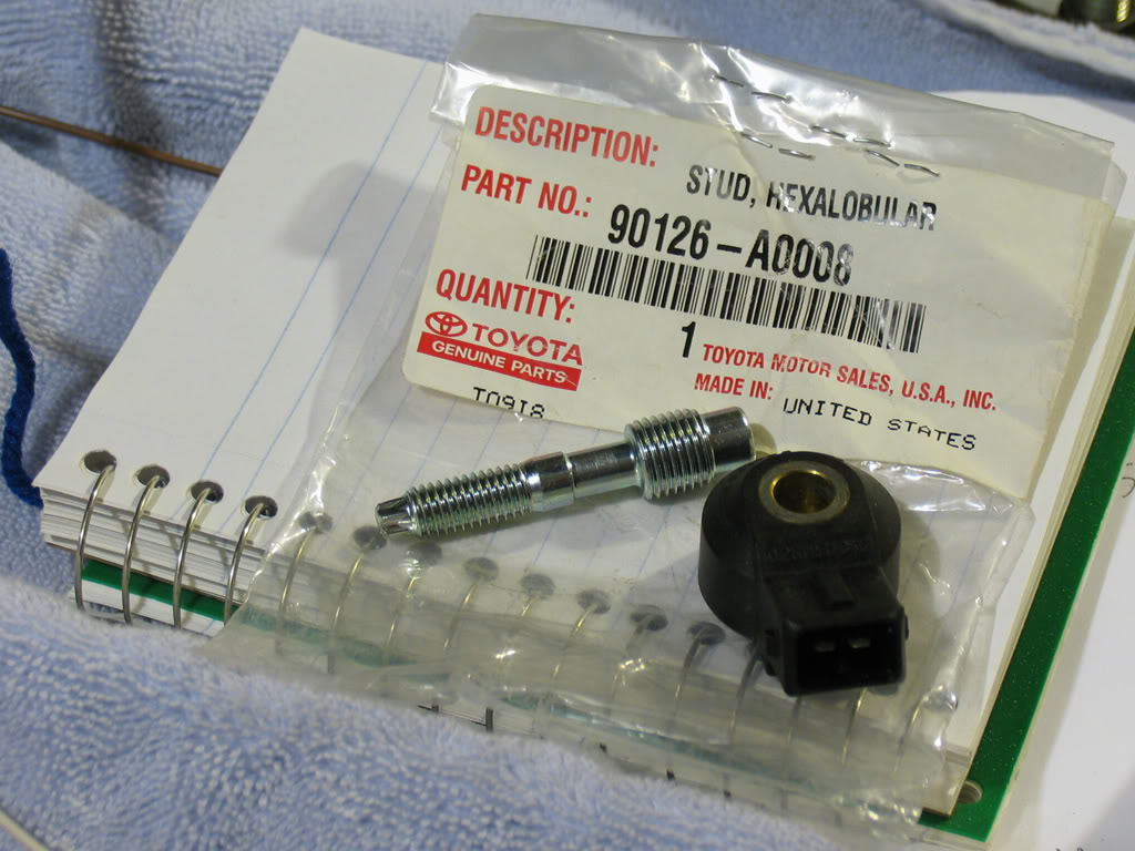
Earlier I said that flat response sensors might work better for you with the AEM than resonant ones. The reason for this is that the knock frequency that your engine is actually producing may be different from the resonance of the sensor. With the stock 2JZ resonant knock sensors I discovered it was very far off. The sensors, both for the GE and GTE, have a sharp spike in output right around 8kHz with a bandwidth of just 500Hz or so. I'm sure there's a reason why Toyota chose this, but with the S2 AEM, I don't think they work very well. Below is the output from the stock sensor. The bandpass filter on this chip is fairly broad with a Q of 2.3. With a center frequency selection of 6.64kHz, the HIP chip will give a -3db bandpass from 5350-8240Hz. If the resonance of the stock sensor was around 6.5kHz or so, they'd work perfectly for us. Knock would produce a large output at the right frequency and we could simply adjust the gain and integrator time constant to get the correct Knock Volts reading. Instead, there is massive background noise that's not excited by knock and it drowns out the relatively smaller knock signal just next to it. Perhaps a center frequency of 5.68kHz or 5.9kHz would filter out the 8kHz spike and allow decent SNR with the sensors. I doubt it, though. I didn't spend much time with them because I switched to Bosch flat sensors. In my opinion, the stock sensors on the 2JZ should be replaced. The next picture below shows the Toyota part number of a stud that allows flat response knock sensors to be used in place of the resonant ones. Big thanks goes to Joe H., carchitect here on the forums, for finding and getting these for me! There was a very slight issue with them that I corrected. It would bottom and the threads would stick out a little and prevent the Bosch sensor from sitting flush against the block. I ground down the big end so they'd sink down a little further, just a few mm. Easy fix. Torque on these is 15 p/f and output is greatly dependent on this, so if they aren't torqued exactly the same then you'll see this in log data. Even after torquing, I saw a slight offset in the data and had to go back and reduce and increase torque very slightly between them. The sensors can be found really easily, even at the bone yard.
**EDIT: Better fitting stud from Toyota is pn: 90126-08046
Here are some more interesting things I found while setting up knock control:
Sensor placement can have a drastic effect on knock detection. When inducing light knock in cylinder 6 (inline 6), I couldn't detect ANY trace of knock at the front sensor. I had the rear knock sensor plugged into the AEM and Knock 2 Volts showed very clearly there was knock but I couldn't pick up anything from the recording of the front sensor. This really surprised me because I assumed sound would move through the block easily. That's not quite the case!
For those using wasted spark coils, it's critical for you to confirm you have the 1, 1b, 2, 2b ect.. coils set to the right tooth value. Test this by turning off fuel injector #1 and then turning off Coil #1. You should see a drop in RPM with turning off the injector, but you should see no drop with turning off the coil. If it does drop with turning off Coil #1 then you need to change your Ignition Sync option. With 24 Spark Teeth, you will want to add or subtract 12 from Ignition Sync.
First, here's a brief background about engine knock. On the compression stroke, a mixture of fuel and air in the cylinder is compressed and it's temperature rises. (Boyle's Law) Between 40-10° BTDC the ecu will command ignition of this mixture and a controlled burn moving out from the spark plug will start to release heat, increasing pressure even faster. If ignition timing was right, cylinder pressure should peak right around 15° ATDC to get the most mechanical work out of the burned fuel. At that point, the flame has swept across most of the cylinder but only about half of the energy has been released. At a certain temperature for a given fuel, the mixture will autoignite (knock), which is essentially a bomb going off in the cylinder causing an extreme pressure spike. Although pressure may peak around 15° ATDC (or well before or after depending on ignition timing and burn rate), temperature is still increasing because of the burning fuel, and there's still a large amount of energy waiting to be released. It's in the 0-50° ATDC region that knock will occur. Generally, knock at an earlier crank angle will be more intense since there is more fuel available to spontaneously combust. Combustion chamber shape will have an effect on required timing advance. Less timing advance is needed for a small displacement pentroof combustion chamber. More timing advance is needed for a large displacement wedge combustion chamber. This has an effect on propensity to knock due to the amount of time the air and fuel mixture has to heat up. The faster burning design being less knock prone. A term that I've often seen associated with knock is pre-igniton. Pre-ignition is the ignition of the mixture before the spark plug fires and is caused by hot spots in the cylinder. Pre-ignition will almost certainly lead to knock. Sustained, severe knock will break ring lands, blow head gaskets, and melt holes in your pistons. The heaviest hand in reacting to spark knock is ignition timing retard since this variable will have a drastic effect on cylinder pressure and temperature. Increasing fuel will also absorb more heat, so a combination of these are what we implement to combat knock. For more on this subject, check out chapter 9 of Heywood's book, Internal Combustion Engine Fundamentals.
There is an important distinction with acoustic knock sensors. There are resonant type, like what come on my Toyota 2JZ engine, and flat response type. Resonant sensors are nice because the frequency filtering is done mechanically and this can save money on the ECU side by not requiring electronic filtering. They are tuned for a particular engine, though. Their output is like a bandpass filter, boosting a small range of frequencies and attenuating all others. Flat response sensors can be used on any engine and give OEM calibrators the ability to use much more complex knock detection strategies. Their output doesn't boost or attenuate any frequencies so you get a true representation of the sounds coming from the engine. Because the cost of the electronics has come down, flat response sensors have become a lot more common. Voltage output of resonant sensors is significantly higher than flat ones but you can set either type to work in the AEM software. Pictured below is a flat and a resonant response sensor. In my opinion, to get the most out of the AEM S2, you will want to switch to flat response sensors. I'll discuss this later.
The S2 AEM uses the Intersil HIP9011 Knock IC. This chip has been around since the mid 1990s, but you'll still find it in a lot of the top aftermarket ecus to this day. The datasheet on this chip details it's design and operation.http://www.intersil.com/content/dam/Intersil/documents/fn43/fn4367.pdf You may also come across the Texas Instruments TPIC8101, which is a clone of the HIP9011. On the AEM main board, there are two of these ICs and I can see traces going to both input channels on each chip. I don't know the purpose of this since each chip has two channel inputs and all the S2 pinouts show only 2 knock sensor inputs. It would be very interesting to hear from an AEM engineer about what strategy they're employing with two of these chips...
The block diagram below outlines each stage of signal processing in the HIP9011. In the software, we have control over the gain, bandpass filter frequency, and integrator time constant.
What we don't have control over is the knock window. The integration period (knock window) is controlled by the main CPU and is usually based off of crank degrees relative to TDC of each cylinder. I'm not 100% sure what AEM is using to trigger the time and length of this integration period. AEM, please let us know! Pictured below is a trace of the knock sensor signal, integration command from the CPU, and integrator output from the HIP9011.
What we see here is a digital signal (high or low) from the CPU to the INT/HOLD pin on the HIP9011 chip. When this signal goes high, the integrator resets to .125V and begins ramping up from there. If, for example, the integration period is 50°, at 3000rpm, this period would be 2.77ms. Over that period, output from the knock sensor is processed by the op-amp, BP filter, and gain stages. These parts, along with the integrator time constant option, determine how quickly the integrator level rises. At the end of the integration period, the command to the INT/HOLD pin goes low and the chip will output the integrated voltage level at the INTOUT pin. This is what the CPU reads as the energy level for that last combustion event. This voltage level is held until the next power stroke comes along and it all starts over. The sharp pulse from a knock event will cause a corresponding sharp rise in the integrator and you'll see this as a higher voltage level over non-knocking cycles.
For reference, some other knock detection strategies look at crankshaft acceleration with a high resolution crank trigger, or even ion sensing at the spark plug on some high end cars. More advanced acoustic detection methods use digital signal processing, handled completely within the main CPU, and look at multiple frequencies and even the characteristic descending pitch signature of a knock event. The analog bandpass filtered, gated, rectified, and integrated scheme that AEM uses with the S2 isn't cutting edge, but it's served as a OEM standard for many years and still does a hell of a job. Some of the ECUs in LeMans and other high profile racing series still utilize this same chip/strategy for knock detection.
Engines produce all sorts of noise across the entire frequency spectrum. Accurate detection gets more difficult as rpm rises due to increasing noise levels. Reducing this background noise starts with the bandpass filter and is further reduced by the knock window. There is a formula that predicts the knock frequency based on bore size. It is: Knock Frequency = 900/(pi * 0.5 * bore in mm) This works really well, but there can be variances between engines by several hundred hertz +/- depending on all sorts of things. We have 64 choices of frequency from 1-20kHz in the software. If you get it right, the system will be able to distinguish between incipient and severe knock. Select a frequency above or below the optimal point and detection will be less accurate. Background noise will be a much larger part of the sample and any knock will be attenuated, seriously decreasing the knock (signal) to background (noise) ratio. You can use the calculated frequency, which will get you close, but you're better off finding it empirically through testing of your knock sensor on your particular engine. This will ensure you get the best signal to noise ratio and, therefore, the most effective knock detection. For the 2JZ engine, this calculated knock frequency is around 6.7kHz, but I've found that the fundamental frequency is closer to 6.4kHz for my motor. There are also ringing frequencies which you might choose if you have a particularly noisy engine. These will be less consistent throughout all operating conditions though, so I believe looking at the fundamental frequency is the best choice. To find it, you simply have to plug your knock sensor into the mic input on your laptop and record your motor while inducing light knock. Set the mic input level so you aren't clipping it at redline. I use a program called Goldwave to produce the recordings and another called Spectrogram to see the frequency content of the recording. It is critical that you record the knock sensor you will be using with the EMS and that it's mounted in the stock location(s). Sensor placement is extremely important so don't just find a spare sensor and bolt it into a free spot on the block! The procedures below assume you are starting with a safe and decent running tune. If you have no experience tuning, DON'T ATTEMPT ANY OF THIS!! Take your car to a tuner.
I decided to switch the knock sensors on my 2JZ engine from resonant to flat, so what you see below are recordings from a Bosch flat response sensor. I'll talk about why I switched a little later. There is no danger to your engine with brief, light load knock so this is where you want to start gathering data. I wanted to isolate only one knocking cylinder and keep all the others out of knock. The 2JZ has a front and rear knock sensor, so I plugged the front one into my laptop mic input and drove cylinder 1 into light knock. To do this, I varied the two tables, Injector 1 Trim and Coil 1 Ign Trim, leaning a/f and adding timing only at 3200rpm. I recorded several tests, adding a couple of degrees and removing a couple % fuel each time then listened and looked at the recording after each. It was around +15° and 10% lean before I saw any knock. I simply drove at about 25% throttle in 2nd or 3rd gear up to 3200rpm then let off. Below is what light load knock looks like in Spectrogram.
What you see are yellow dots centered right around 6.3kHz. 6.37kHz is what I selected in the software for Knock Frequency. Knock may sounds kind of like a bird chirping. When slowed down to about 1/10th speed, it'll sound like hitting an empty tin can with a stick. It's a very sharp pop and easy to identify. You'll see it as vertical lines in the spectrogram. The lowest frequency is the fundamental and the higher ones are the ringing frequencies. The fundamental will correspond most closely with knock intensity and it will be a lot more consistent than the ringing ones.
I also did WOT tests by removing 4° from all cylinders except #1. I crept up one degree at a time, taking recordings for each pull. After each pull, I reviewed the recording to listen and see if there was any knock. If your motor is turbocharged, do this at the lowest possible boost.
Once you have the frequency set, you can then start to take logs and set the gain and integrator time constant. These two options have a large effect on the Knock Volts channel. Gain is very easy to understand, it's just like the volume knob on a radio. Since the output of flat response sensors is so low, you will likely need to set this to the highest value of 2. Resonant sensors will probably need a 0.1 to 0.5 stetting.
The integrator time constant functions as an output signal attenuator. A shorter integrator time constant will cause a steeper rise in the integrator voltage and, therefore, a higher voltage at the INTOUT pin. A longer integrator time constant will produce a lower output voltage. With flat sensors, a Knock Integrator value of 150-200 and a gain of 2 seems to give excellent results. When logging Knock 1/2 Volts, you'll want the highest level, at redline, to be somewhere around 1-1.25v range. What I've seen with an integrator time constant of 200 or higher is that a knock event will not stick out as much over the noise floor. If it's below 100, the knock free background noise will cause Knock Volts to reach over 3-4v and our range is only up to 5v. With too short a time constant, even light knock would send the knock channel to the max of 5v and there would be no way to tell how severe the knock actually was. Different engines might want slightly different values. I'd recommend changing gain and leaving the integrator option around 180 if possible. The pic below shows Knock 1 Volts output with a gain of 2, freq of 6.37, and various Knock Integrator values.
Pictured below is the logged data I got with light knock in only cylinder 1.
Here you can see knock being induced at WOT for cylinder 1 and 6 and corrective action taking place. As you can see, there is great signal to noise even at high rpm. Once you've decided on the frequency, gain, and integrator values, you can use the Knock Volts level you get from a knock free WOT pull to set your Knock Sensor Cal table.
I recently went to a track day and could see knock activity increasing as engine temperatures increased. Also, some burst knock with quick throttle application. Having logging and excellent knock detection allows you to refine your map for situations beyond what you're exposed to on the dyno. Accel fuel, ignition map, and ignition trim tables were modified based on this data.
Choosing the right corrective action will depend on the signal levels you're getting from Knock Volts. You might see incipient knock of .5v above the base and want to pull a degree or two. Severe Knock might be 1.5v or more above the base. The max timing retard I'd recommend is 10°, so you'd probably want to set the Knock Retard/Volt option to 5 or 6. 2-3% would be a decent setting for Knock %Rich/Volt with a max of 8%. Knock restore can be in the 50-100ms range. These settings may evolve as you gather more data over time.
Earlier I said that flat response sensors might work better for you with the AEM than resonant ones. The reason for this is that the knock frequency that your engine is actually producing may be different from the resonance of the sensor. With the stock 2JZ resonant knock sensors I discovered it was very far off. The sensors, both for the GE and GTE, have a sharp spike in output right around 8kHz with a bandwidth of just 500Hz or so. I'm sure there's a reason why Toyota chose this, but with the S2 AEM, I don't think they work very well. Below is the output from the stock sensor. The bandpass filter on this chip is fairly broad with a Q of 2.3. With a center frequency selection of 6.64kHz, the HIP chip will give a -3db bandpass from 5350-8240Hz. If the resonance of the stock sensor was around 6.5kHz or so, they'd work perfectly for us. Knock would produce a large output at the right frequency and we could simply adjust the gain and integrator time constant to get the correct Knock Volts reading. Instead, there is massive background noise that's not excited by knock and it drowns out the relatively smaller knock signal just next to it. Perhaps a center frequency of 5.68kHz or 5.9kHz would filter out the 8kHz spike and allow decent SNR with the sensors. I doubt it, though. I didn't spend much time with them because I switched to Bosch flat sensors. In my opinion, the stock sensors on the 2JZ should be replaced. The next picture below shows the Toyota part number of a stud that allows flat response knock sensors to be used in place of the resonant ones. Big thanks goes to Joe H., carchitect here on the forums, for finding and getting these for me! There was a very slight issue with them that I corrected. It would bottom and the threads would stick out a little and prevent the Bosch sensor from sitting flush against the block. I ground down the big end so they'd sink down a little further, just a few mm. Easy fix. Torque on these is 15 p/f and output is greatly dependent on this, so if they aren't torqued exactly the same then you'll see this in log data. Even after torquing, I saw a slight offset in the data and had to go back and reduce and increase torque very slightly between them. The sensors can be found really easily, even at the bone yard.
**EDIT: Better fitting stud from Toyota is pn: 90126-08046
Here are some more interesting things I found while setting up knock control:
Sensor placement can have a drastic effect on knock detection. When inducing light knock in cylinder 6 (inline 6), I couldn't detect ANY trace of knock at the front sensor. I had the rear knock sensor plugged into the AEM and Knock 2 Volts showed very clearly there was knock but I couldn't pick up anything from the recording of the front sensor. This really surprised me because I assumed sound would move through the block easily. That's not quite the case!
For those using wasted spark coils, it's critical for you to confirm you have the 1, 1b, 2, 2b ect.. coils set to the right tooth value. Test this by turning off fuel injector #1 and then turning off Coil #1. You should see a drop in RPM with turning off the injector, but you should see no drop with turning off the coil. If it does drop with turning off Coil #1 then you need to change your Ignition Sync option. With 24 Spark Teeth, you will want to add or subtract 12 from Ignition Sync.
XXX . XXX 4 zero null 0 How Electronic Fuel Injection Works
New cars are confusing. With all the computers, sensors, and gadgets, it may seem like there's some sort of magical witchcraft taking place under the hood. We're here to show you how modern automotive computer control systems work. Last week, we looked at variable valve timing. Today's topic: Electronic Fuel Injection.
Back in the day, a good ol' carburetor was responsible for sending the appropriate amount of fuel into the cylinders. Today, that job belongs to the ECU.
Let's see how it works.
For a lot of you this is review, but if we want a new generation of car enthusiasts to care about cars, it can't hurt to explain how they actually work.
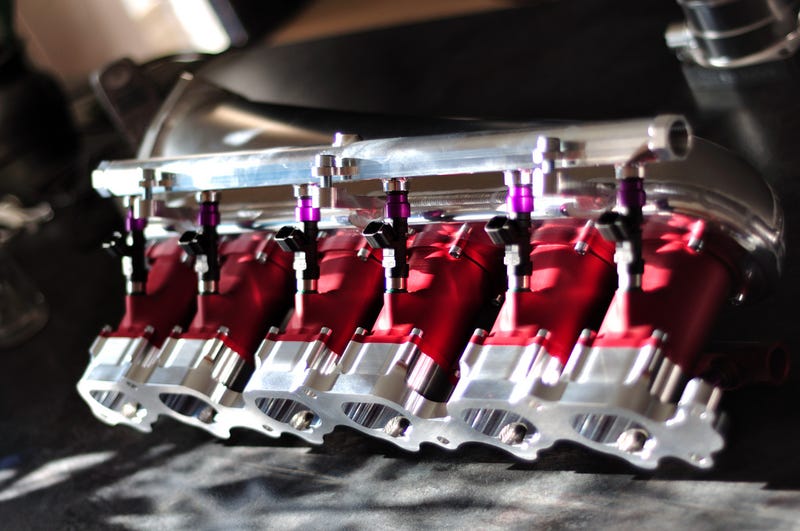
ELECTRONIC FUEL INJECTION
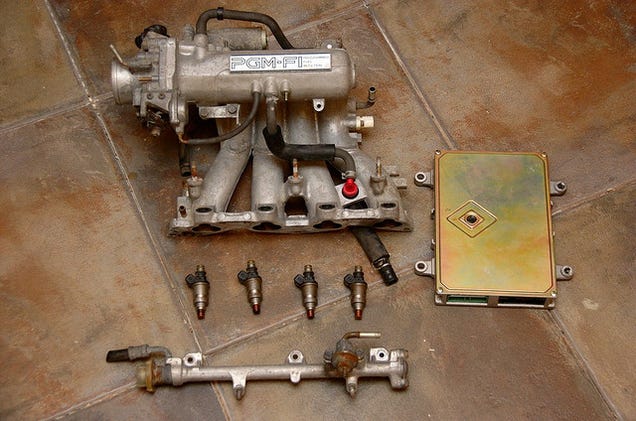
Photo Credit: Albertas Agejevas
If the heart of a car is its engine, then its brain must be the Engine Control Unit (ECU). Also known as a Powertrain Control Module (PCM), the ECU optimizes engine performance by using sensors to decide how to control certain actuators in an engine. A car’s ECU is primarily responsible for four tasks. Firstly, the ECU controls the fuel mixture. Secondly, the ECU controls idle speed. Thirdly, the ECU is responsible for ignition timing. Lastly, in some applications, the ECU controls valve timing.
Before we talk about how the ECU accomplishes its tasks, let's follow the path of a gasoline droplet that enters your gas tank. Times have changed since the Down the Gasoline Trail video, so it's time for an update. Initially, after a gas droplet enters your gas tank (which is now made of plastic), it gets sucked up by an electric fuel pump. The electric fuel pump usually comes in an in-tank module that consists of a pump, a filter, and a sending unit. The sending unit uses a voltage divider to tell your gas gauge how much fuel you have left in your tank. The pump sends the gasoline through a fuel filter, through hard fuel lines, and into a fuel rail.
A vacuum-powered fuel pressure regulator at the end of the fuel rail ensures that the fuel pressure in the rail remains constant relative to the intake pressure. For a gasoline engine, fuel pressure is usually on the order of 35-50 psi. Fuel injectors connect to the rail, but their valves remain closed until the ECU decides to send fuel into the cylinders.
Usually, the injectors have two pins. One pin is connected to the battery through the ignition relay and the other pin goes to the ECU. The ECU sends a pulsing ground to the injector, which closes the circuit, providing the injector's solenoid with current. The magnet on top of the plunger is attracted to the solenoid's magnetic field, opening the valve. Since there is high pressure in the rail, opening the valve sends fuel at a high velocity through the injector's spray tip. The duration that the valve is open- and consequently the amount of fuel sent into the cylinder- depends on the pulse width (i.e. how long the ECU sends the ground signal to the injector).
When the plunger rises, it opens a valve and the injector sends fuel through the spray tip and into either the intake manifold, just upstream of the intake valve, or directly into the cylinder. The former system is called multiport fuel injection and the latter is direct injection.

Diagram from Wikipedia
Controlling Fuel Mixture

We've already looked at how electronic throttle control works. We showed you that, when a driver pushes his or her gas pedal, an accelerator pedal position sensor (APP) sends a signal to the ECU, which then commands the throttle to open. The ECU takes information from the throttle position sensor and APP until the throttle has reached the desired position set by the driver. But what happens next?
Either a mass air flow sensor (MAF) or a Manifold Absolute Pressor Sensor (MAP) determines how much air is entering the throttle body and sends the information to the ECU. The ECU uses the information to decide how much fuel to inject into the cylinders to keep the mixture stoichiometric. The computer continually uses the TPS to check the throttle’s position and the MAF or MAP sensor to check how much air is flowing through the intake in order to adjust the pulse sent to the injectors, ensuring that the appropriate amount of fuel gets injected into the incoming air. In addition, the ECU uses the o2 sensors to figure out how much oxygen is in the exhaust. The oxygen content in the exhaust provides an indication of how well the fuel is burning. Between the MAF sensors and the 02 sensor, the computer fine-tunes the pulse that it sends to the injectors.
Controlling Idle

Photo Credit: Aidan
Let's talk about idling. Most early fuel injected vehicles utilized a solenoid-based idle air control valve (IAC) to vary air flow into the engine during idle (see the white plug in the above image). Controlled by the ECU, the IAC bypasses the throttle valve and allows the computer to ensure smooth idle when the driver does not activate the accelerator pedal. The IAC is similar to a fuel injector in that they both alter fluid flow via a solenoid actuated pin.
Most new cars don't have IAC valves. With older cable-controlled throttles, the air entering the engine during idle had to go around the throttle plate. Today, that's not that case, as Electronic Throttle Controlsystems allow the ECU to open and close the butterfly valve via a stepper motor.
The ECU monitors the rotational speed of the engine via a crankshaft position sensor, which is commonly a Hall Effect sensor or optical sensor that reads the rotational speed of the crank pulley, engine flywheel, or the crankshaft itself. The ECU sends fuel to the engine based upon how fast the crankshaft rotates, which is directly related to the load on the engine. Let's say you turn on your air conditioning or shift your vehicle into drive. The speed of your crankshaft will decrease below the threshold speed set by the ECU due to the added load. The crankshaft position sensor will communicate this decreased engine speed to the ECU, which will then open the throttle more and send longer pulses to the injectors, adding more fuel to compensate for the increased engine load. This is the beauty of feedback control.
Why does your engine rev higher at startup? When you initially turn on the vehicle, the ECU checks the engine temperature via a coolant temperature sensor. If it notices that the engine is cold, it sets a higher idle threshold to warm the engine up.
Controlling Ignition Timing

Photo Credit: AJ Hill
Now that we've mentioned the ECU’s tasks of maintaining engine idle speed, as well as maintaining a proper air/fuel mixture, let's talk about ignition timing. To achieve optimum operation, the spark plug must be provided with current at very precise moments, usually about 10 to 40 crankshaft degrees prior to top dead center depending on engine speed. The exact moment that the spark plug fires relative to the piston’s position is optimized to facilitate the development of peak pressure. This allows the engine to recover a maximum amount of work from the expanding gas.

Older engines (up until the mid 2000s) used distributors to control spark. Shown above, this system consists of a rotor and a distributor cap. The rotor is electrically connected to the ignition coil, which is basically a transformer that steps 12v up to over 10,000 volts needed for spark. The rotor is mechanically connected to the camshaft via a gear. As the camshaft spins, so does the rotor. As the rotor spins, it comes very close to copper posts (one for each cylinder). The current from the ignition coil jumps the small air gap between the rotor and the posts, sending high voltage through spark plug wires, to each cylinder's spark plug at a specific time. Note that these systems needed a way to alter timing. At high engine speeds, advancing spark is necessary. Early engines with distributors used engine vacuum or rotating weights to adjust timing. Later, transistor-based timing systems became more common.
Modern vehicles don't use a centrally located ignition coil. Instead, these distributorless ignition systems (DIS) have a coil located on each individual spark plug. Based on input from the crankshaft position sensor, knock sensor, coolant temperature sensor, mass airflow sensor, throttle position sensor, and others, the ECU determines when to trigger a driver transistor, which then energizes the appropriate coil.
The ECU is able to monitor the piston’s position via the crankshaft position sensor. The ECU continually receives information from the crankshaft position sensor and uses it to optimize spark timing. If the ECU receives information from the knock sensor (which is nothing more than a small microphone) that the engine has developed a knock (which is often caused by premature spark ignition), the ECU can retard ignition timing so as to alleviate the knock.
Controlling Valve Timing
The fourth major function of the ECU is to adjust valve timing. This applies to vehicles that utilize variable valve timing, which allows engines to achieve optimal efficiency at a multitude of engine speeds. See last week's article for more on that.
Power Electronics
The Power Electronics includes an inverter and a DC/DC converter. The inverter converts the direct current of the battery into the three-phase alternating current that is required by the electric motor. During recuperation, the power electronics converts the alternating current generated by the electric motor into direct current, and thus charges the battery. The DC/DC supplies the 12 Volt board net of the hybrid and electric vehicles with power, which makes the 12 Volt alternator redundant.
Augmented-Reality HUD
In the near future augmented reality head-up displays will help to make driving even more comfortable and safe. This generation of HUDs supplements the exterior view of the traffic conditions in front of the vehicle with virtual information (augmentations) for the driver.
- The augmented reality head-up display differs from a normal windshield-HUD since the reflected information appears to be part of the driving situation itself
- When navigating, for example, a virtual symbol inserted precisely into the exterior view marks the route that the driver should follow on the road ahead
- When distance controls (adaptive cruise control, ACC) are enabled, a marking in the AR-HUD visualizes which vehicle in front is detected by the assistance system
In a world that is becoming increasingly complex, the AR-HUD relieves the burden on the driver because what the driver’s eyes see is directly connected with explanatory information.
This leads to a new quality of information that allows the driver to register the driving situation they are in even faster – essential for more safety and comfort.
This leads to a new quality of information that allows the driver to register the driving situation they are in even faster – essential for more safety and comfort.
Multipurpose Processing Platform
The Assisted & Automated Driving Control Unit facilitates a safe & secure multipurpose processing platform ideally suited for applications in the realm of Highly Automated Driving (HAD). This is achieved by integrating selected HW and SW, that is monitoring a vehicle's motion and guiding its routing states at runtime. Moreover, ADCU executes an Environment Model (EM) based on signal feeds retrieved from onboard surveillance sensors and additional info. This is passed along to its trajectory planning algorithms to determine the optimal (ecological, safe, convenient) path and to coordinate the multitude of Actuators (e.g. brake, suspension, etc.)
XXX . XXX 4 zero null 0 1 2 3 Open loop compensation circuit
A closed loop fuel management system is disclosed in which an improved dual integral controller provides both transient and gross correction for an electronic fuel injection system operating at a predetermined air/fuel ratio. The controller has cascaded dual integrator including a primary integrator with a relatively fast integration rate utilized for transient control and a secondary integrator with a relatively slow integration rate utilized for gross control such as ageing effects and altitude compensation. The controller responds to several engine operating conditions and to rich fuel power demands to switch from closed loop to open loop control while maintaining the gross system correction provided by the operating point of the secondary integrator.

me a new windshield, but by Daytona Bike Week 2010, I still hadn’t gotten the dents fixed.
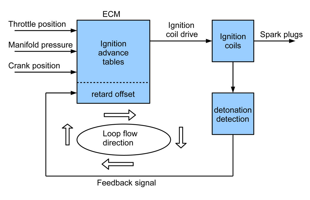 Harley’s Delphi antiknock ignition system is a basic, closed-loop feedback system. Any detonation is detected and eliminated within a few engine revolutions. |
SENSORS AND LOOPS 101
If you don’t understand this O2 sensor, open- and closed-loop stuff, you’ll be a sucker for guys who use them as buzzwords with the intent of opening your wallet. Let’s start the lesson by taking a look at another closed-loop system that does its job so well on Twin Cams that we rarely even notice it: the antiknock ignition system. It has several inputs, as shown in the diagram above. From them, the ignition section of the bike’s electronic control module (ECM) continuously outputs the proper spark advance and timing from its advance charts. So far, we have a basic system that works well, but can’t optimize timing for fuel octane or compression changes. To achieve that, we add what’s known in electronics as feedback, where a sample of the output is fed back to the processor. When drawn on a diagram like the one here, the information flow looks like a circle or a loop. It’s called closed-loop to distinguish it from open-loop, which is when feedback is not used. In the closed-loop ignition system, the feedback signal is generated by a detonation detection circuit and used to retard the ignition system as needed. The process goes on continuously and is unnoticed by the rider, except when he may hear a momentary pinging as the system adjusts to load and throttle changes. Wouldn’t it be nice if the fuel system was as transparent?The fuel system adds head and intake air temperatures as inputs to the ECM. Throttle position is measured at the throttle body on the engine (2008 and later Touring models have an electronic throttle so the position may lag in the rider’s throttle hand). The top section of the fuel system diagram below shows the system used on all non-O2 Delphi EFI Twin Cams. The cam position sensor times the injector pulse and the fuel tables set the fuel injector’s pulse length and, therefore, the volume of fuel injected. The fuel tables are lists of pulse lengths based on throttle opening, manifold pressure, and engine rpm. When combined with the ignition tables, they’re often called maps because the ECM is constantly moving around on them as the bike is ridden. The basic fuel tables are set to produce air/fuel ratios (AFRs) of about 14:1 at low throttle openings, gradually getting richer as the throttle is opened to 13:1 at full throttle. This gives good fuel mileage, responsive performance, and maximum horsepower. The intake and head temperatures offset the tables, adding a little more fuel to keep the engine running smoothly when either the engine or weather is cold.
Enter the O2 sensors and closed-loops in 2006. Why were they added? Some people will say they were added to help the bike adjust for weather and altitude changes. Absolutely not! As a matter of fact, as we’ll see shortly, the opposite is true. Plus, didn’t we just see that the pre- O2 system already adjusted for temperature? And altitude is automatically tracked since atmospheric pressure changes show up at the manifold pressure sensor. No, the O2 sensors were added for one reason only: to control exhaust emissions the same way they have on cars and trucks since the 1980s. They allow for that good old 14.7:1 stoichiometric AFR that yields the most complete combustion and thus minimum emissions. You may also see the 14.6:1 AFR used in various places. Close enough, they’re interchangeable. When I first wrote about going to 14.7 in the autumn of 2006, it seemed like a good idea. But, slowly, we started to see the downside: heat and lots of it. The summer of 2007, when the O2s made their way into all models, was a particularly hot one for new Harley owners. Owners were adding fans and oil coolers. They were going to true dual exhausts on Touring models just to get rid of the rear pipe’s heat radiation on the right side. When the Motor Company realized the scope of the heat problem, it added the parade mode, which shuts down the rear cylinder at idle. Then, in 2009, Harley routed the exhaust under the frame. The problem is that the heat source is still there, and the air-cooled engine has no good way to control it or, as I say, to turn off the toaster.
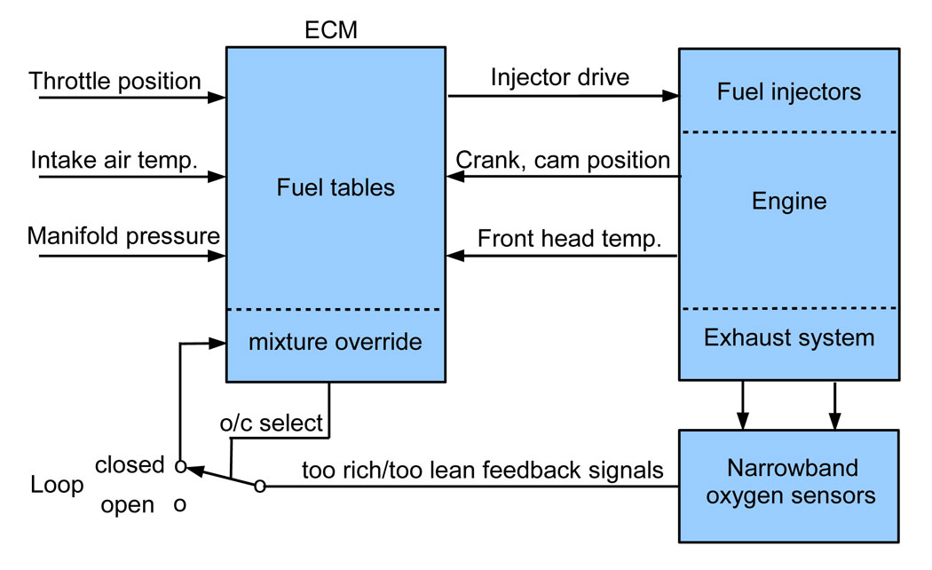 This is the ECM fuel section used on the 2006 Dynas and all models from 2007 to present. In closed-loop mode the O2 sensors override the fuel maps that otherwise would compensate for temperature and altitude. |
A CASE STUDY
The AFR graph below shows a 96" Road Glide running at about one-quarter throttle and making 25 hp during my cruise test. As I held it at about 1400 rpm, it ran closed-loop at 14.7:1. When I twisted the throttle one-quarter open, notice that the rear cylinder (red) went a little lean, running open-loop on its fuel table during the acceleration. Any leaner and we would have had a stumble. At a steady, one-quarter throttle, we can see the hunting action that averages to 14.7 as near as we can tell. Although the engine would be happier closer to 14.0, 14.7 isn’t too bad at quarter throttle and 25 hp. The problem is, it will still be that lean at three-quarter throttle while trying to make 60-plus hp. At those power levels, things get real hot, real fast due to serious fuel starvation. And look what happened when the ECM opened the loop at 4600 rpm. The front cylinder (blue) headed right for 13:1, exactly what we want to see, but the rear headed for meltdown. It’s interesting that at full throttle (not shown), which is open-loop at all rpm since it’s over three-quarter throttle, the rear cylinder AFR ran closer to the target 13:1 than the front. Does this mean the system learns, allowing us to change airflow components with impunity and it will adjust? Well, yes and no. As long as the changes are small enough, such as air filter and pipes, the system will still be able to achieve 14.7. However, that doesn’t change the fuel tables the hunting starts from, meaning it hasn’t really learned. With a large enough change, such as cams or cubes, not only will the open loop tables be way off, closed-loop lock may not be achievable either.FIXES FOR 02-CAUSED HEAT
What we’ve seen is that the O2 sensor equipped Twin Cam and Sportster models run in two separate and distinct modes, closed-loop on the sensors at idle and cruise, and open-loop on their fuel tables or maps on acceleration and at top end. If you can live with "normal," your bike’s engine can, too. And with synthetic oil, the engine won’t get hot enough to hurt itself.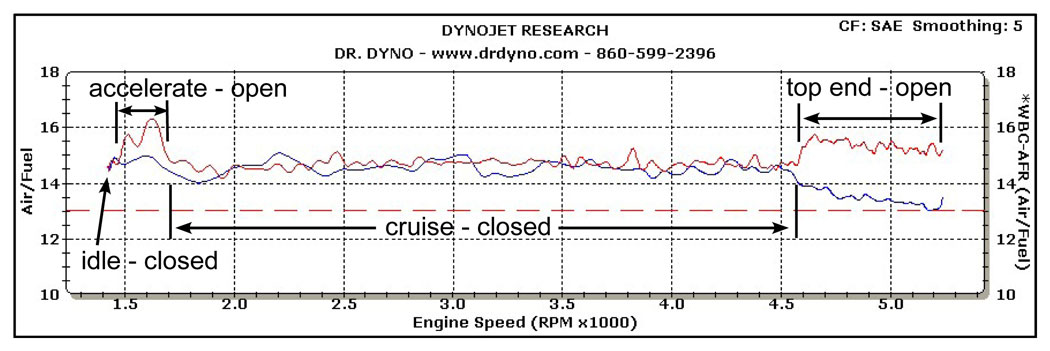 This typical AFR graph done at a 25 hp cruise shows the open- and closed-loop areas of operation. It’s lean at idle and cruise where it hunts for 14.7:1 and extra lean on the rear cylinder (red) at both ends. |
Street-legal tuning products are available for closed-loop bikes, but keep in mind that they only work in the open-loop area. Two such products are the Dynojet Power Commander III EX and the Vance & Hines Fuelpak EX. A description of Fuelpak EX I found on www.Fuelpakfi.com explains that it “works in conjunction with your motorcycle’s factory oxygen sensors and provides improved fuel delivery at higher rpm and throttle openings.” In a way, it explains what the Fuelpak doesn’t do: it doesn’t change idle or cruise because it doesn’t bypass the oxygen sensors. Occasionally, someone brings me a Harley with a PCIII-EX he bought because it was the newest model at the time, and it’s street-legal. I replace it with a PCIII-usb, install the O2 eliminators, and dyno tune the bike as if it was pre-O2 vintage. It’ll run perfectly, and anytime he wants it to meet emissions, the owner can simply reconnect the O2 sensors.
Lastly, there’s the whole area of software tuners that change the programming inside the bike’s ECM. The sky’s pretty much the limit with these types, both good and bad. It takes hours to get it just right, but a good tuner can make a bike run perfectly. To make it run terriblely only takes a few minutes. The problem for the customer is, unlike an external device such as a Power Commander, the bike’s ECM is write only so the maps can’t be read from the ECM. The only place where the changed ECM data is stored is in the tuner’s computer. Unless he gives you a copy on a memory stick, it’s start over for any other tuner who might work on your bike. A good tuner won’t give you the maps because they’ll get passed around for free or sold, costing him business. Of course, lesser tuners don’t want anyone seeing their bad maps either. And neither one will tell you they’re going to lock you in up front, so you need to be especially confident about who you allow to mess with your bike’s ECM. AIM


++++++++++++++++++++++++++++++++++++++++++++++++++++++++++++++++++
++++++++++++++++++++++++++++++++++++++++++++++++++++++++++++++++++
CLIP AND CLAMP ELECTRONICS COMPARE ELECTRONIC FUEL INJECTION
++++++++++++++++++++++++++++++++++++++++++++++++++++++++++++++++++
Tidak ada komentar:
Posting Komentar