
let's discuss how to draw and pour the idea idea of a physics function in helping to improve the working patterns of humans in the multi-dimensional climate of life and more to have purity of heart
electronics diagrams are divided into several forms:
1 dimensional form:
just as a progressive storyline
only as a fascinating memory behind the positron tension valence bond
just as dots and sand on tracing paper
just as a virtual connecting point
just as the underwater caterpillars are depicted oscillating
just as the canal ends in space
just a fantasy story
2 dimensional form:
just as an electron pathway
just as an abstract view of the description
just a picture there is no natural function
only images blown in air vacuum

3 dimensional form:
only as a body without spirit and soul
only images can be counted in series
just a picture of half-imaginary meaning
an image that has not been real to be an actual function
images to learn
signal image and uncertain work
4 dimensional shapes 5, 6 9, .... 10
electronic schematic drawings that already have the time time detected by the solar system
electronic schematic drawings that can see the justice of space without energy
electronic schematic images that can detect the motion of the solar system from the former constant of the future
electronic schematic images that can move forward quickly and slowly
electronic schematic drawing without using paper
electronic schematic drawing is very entertaining spirit
XX . 0 Circuit and schematics


Circuit Diagram Drawing Software
When it comes to drawing circuit diagrams, it’s damn hard to get a clear overview of all the benefits and functionalities different tools have to offer. However, in the end, everybody needs one, so it’s important to know which circuit diagram maker is best tailored to your personal needs.
In the virtual world, an electronic component is represented by a symbol. These symbols are used in the 2D and 3D representation of diagram circuits. All these symbols are linked with straight lines that represent the electrical wires. Taking a step further, all these symbols and lines form a diagram that is used to show you how to connect in an optimal way the electronic components. The final step is using the simulation tool to determine the design defects and deficiencies.
In the following, we explore a series of online and computer software tools for drawing circuit diagrams.
In this category, I made a list with several free online tools that run in a browser and useful for drawing circuit diagrams.

In the following you have available a series of computer software tools to draw and simulate electronic circuits and diagrams.

In the virtual world, an electronic component is represented by a symbol. These symbols are used in the 2D and 3D representation of diagram circuits. All these symbols are linked with straight lines that represent the electrical wires. Taking a step further, all these symbols and lines form a diagram that is used to show you how to connect in an optimal way the electronic components. The final step is using the simulation tool to determine the design defects and deficiencies.
In the following, we explore a series of online and computer software tools for drawing circuit diagrams.
Online tools to draw circuit diagrams
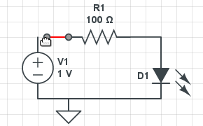
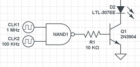
In general, the tools used to draw circuit diagrams in a browser are simple and allows you to produce schematic diagrams at a click away. Any of these online tools can be comparatively with computer software designed for the same purpose. The reason is simple. All the features of a computer software can be implemented in a browser tool for circuit diagrams.In this category, I made a list with several free online tools that run in a browser and useful for drawing circuit diagrams.

SchemeIt (photo source www.aspenlabs.com)
- SchemeIt
With a comprehensive list of electronic symbols and components, SchemeIt is one of the most completed, simple and useful online schematic and diagramming tool. The tool offers support for drawing and export the electronic circuit as an image, or just to share the work with other users. A complete electronic symbol library makes the work easier for everyone. SchemeIt is compatible with almost all web browsers and is free for use. - CircuitLab
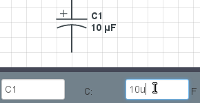
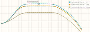
Besides building circuits, the CircuitLab has integrated a simulator designed to be used by anyone to test the electronic schema just using the browser. It has a user-friendly interface and offers an accurate analysis of DC or AC electronic components. The CircuitLab tool uses the drag-and-drop gesture while the electronic elements are linked with fewer clicks.
It can be used for educational purposes or by hobbyists to learn the electronic concepts, or used by practicing engineers to explore the design in the same way as traditional tools. - Draw
Draw is a simple and useful online diagramming application with cloud storage integration to store your files online and access easily the circuit diagrams from anywhere and anytime. The tool is fast, simple and reliable. The Draw was built using mxGraph JavaScript library, and the result is a web application with export options, a lot of symbols and the possibility to embed widget sharing. - Webtronics
Webtronics is a simple and free online tool for designing schematic circuit diagrams. It allows you to export the electronic schema as a simple image, and to import and edit schematic images. - Falstad
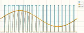
Falstad is an electronic circuit simulator that runs in browser as a Java applet. Its design is based on colors that can indicate for example positive or negative voltage, and allows you to build simple circuits with mouse clicks. - EasyEDA
EasyEDA is a great free web based PCB tool for anyone involved in electronics design and able to share the work with others. The tool allows you to import an old design from several other circuit maker tools, it has the ability to export the designs and simulation results in .PNG or .SVG formats, and can be a host for your partners and colleagues if they want to work on your projects.
Computer software to draw circuit diagrams
A computer software offers different ways to manipulate and organize the electrical circuits including here the possibility to import files, share, and work with complex electronic scheme.In the following you have available a series of computer software tools to draw and simulate electronic circuits and diagrams.

SmartDraw
- SmartDraw
SmartDraw is a free software designed to create diagrams for electronic circuits. It has a simple and friendly interface based on drag-and-drop gestures. The tool uses simple commands for shapes while the program automatically adjusts the position with the appropriate connections. - TinyCAD
Based on standard and custom symbol libraries, TinyCAD is an open source tool for drawing circuit diagrams. - Dia
Dia is a program to draw structured diagrams. - PSPICE 9.1
PSPICE is also available in student version and is used to draw and simulate analog and digital circuits. - KiCad
KiCad is a free EDA software for professional schematics and printed circuit boards. - FreePCB
FreePCB is an open-source and free diagram tool designed for Windows OS with support for import and export files. - Circuit Diagram
Circuit Diagram is an open-source and free software used to design electronic circuit diagrams. The tool has support to export the digital circuit in images. - gEDA
gEDA is a free drawing tool for a large variety of electronic fields including electrical circuit design, schematic capture, simulation, prototyping, and production. - Solve Elec
Solve Elec is a free tool used to draw and analyze electrical circuits for alternative and direct current. The software offers the possibility to integrate documentation in the project. - EAGLE PCB
EAGLE PCB is a software with the aim to offer a complete design tool to experts in electronics. It has incorporated not just one module, it has incorporated three modules embedded in one interface. - EDWinXP
EDWinXP is not just a drawing tool, this is a complete software package used to design electronic products. From an idea to the final product are many stages, and all of these stages are covered by this tool. The EDWinXP has support for 3D designs. - Linear Technology
Linear provides a wide range of tools used for modeling and simulate electronic circuits. - NI Multisim
NI Multisim is a complete tool to draw circuits, and it’s used especially for educational purposes. - PCB123
PCB123 software offers a complete range of tools for design and print circuits. - PowerVue Circuit Analyzer
PowerVue tool is dedicated to electrical engineers and used in small and medium projects. Its features include calculating voltage drops and branch currents and also display voltage and current vectors. - DipTrace
DipTrace is a complete tool and has a friendly interface for drawing schemes. The library is a huge box with over 100,000 parts used to design 3D models. The tool offers support for a large number of output formats in order to fit with various manufacturers. - 5Spice
5Spice offers the ability to integrate the drawing circuits with simulation results, and offer support for an unlimited number of analyzes. - TINA
Tina is a powerful design suite tool with circuit simulation and for PCB design. - AmpereSoft ProPlan
AmpereSoft ProPlan is a complete tool to draw circuit diagrams, assembly plans, terminal tables and part lists. - Stylus Labs
Compatible with Windows, Linux, Mac or Android operating systems, Stylus Labs is a simple software with support for the SVG file format that allows you to view the documents in any browser. - Inkscape
Inkscape has sophisticated drawing tools for diagrams and is one of the designing tools for professional users. It is free and open-source software, which runs on Windows, Mac OS X, and Linux. - AVSnap
AVSnap is a free software to draw a detailed circuit diagram. - OmniGraffle
OmniGraffle is a multipurpose drawing tool with powerful styling tools that can organize diagrams with just one click. - Fritzing
With a large community of users, the Fritzing is a useful design tool for Arduino projects. You can share your work with all users, or you can be helped by people in the community. - LTspice IV
Compatible with Windows and Mac OS X, the LTspice IV is a high-performance SPICE simulator and schematic capture. - Circuit Diagram
A simple Windows design tool for making electronic circuit diagrams.
X . I How to Draw a Circuit Diagram
Circuit Diagram
Standard Circuit Symbols for Designing
Below are some frequently used circuits symbols:
 Cell: A cell stands for electrical energy supply. A single cell is often called a battery, but strictly a battery is two or more cells joined together. It's represented by a long and a short parallel line.
 Battery: A battery is more than one cell. The larger terminal (on the left) is positive (+).It is represented by a collection of long and short parallel lines.
Wire: Pass current from one part of the circuit to another. It's a connecting wire between two components.
Resister: A resister is used to restrict the flow of a current. It's represented by a zigzag line.
Switch: An on-off switch allows current to flow only when it is in the closed (on) position. It's generally represented by providing a break in a straight line by lifting a portion of the line upward at a diagonal.
Ammeter: An ammeter is used to measure current. It's represented by a letter A in a circle.
Voltmeter: A voltmeter is used to measure voltage. It's represented by a letter V in a circle.
Motor: A transducer converts electrical energy to kinetic energy. It's represented by a letter M in a circle.
Lamp: A transducer which converts electrical energy to light.
Start from a Circuits and Logic Template
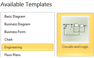
How to Draw Circuit Diagrams with Edraw
Steps:
1. On the File menu, point New, point Engineering and double click Circuits and Logical Template.
2. Simply drag and drop required component symbols from the pre-made library to the drawing page.
3. Add wires to connect the components.
4. Add data to a shape by double clicking on the shape.
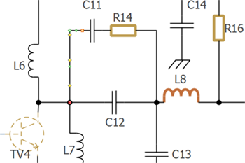
Print: When a circuit diagram is done, it's easy to print and share with more people. On the file menu, point to Print to set for print options. You can change settings with fewer clicks and see the print preview in real time.
Export: Edraw offers support for exporting your diagram to various formats, including Microsoft Office, PDF, and many other graphic formats. On the File menu, point to Export & Send for Export options.
More features make Edraw the best circuits diagram maker:
- Edraw has built in a set of nice looking themes with advanced effects. It's easy to change the whole diagram by changing the active theme with just a few clicks. You don't have to be professional in designing.
- All Edraw documents are vector graphic files with high clarity and available for reviewing and modifying.
- A set of smart tools are provided for automatic formatting. You can easily arrange, rotate, group and align objects.
- Edraw offers various customization options, using which you can adjust line width, line color, line style, font size, font style, text color, and much more.
- Easy to add photos, images and edit text fields.
Circuit Symbols and Circuit Diagrams
Thus far, this unit of The Physics Classroom tutorial has focused on the key ingredients of an electric circuit and upon the concepts of electric potential difference, current and resistance. Conceptual meaning of terms have been introduced and applied to simple circuits. Mathematical relationships between electrical quantities have been discussed and their use in solving problems has been modeled. Lesson 4 will focus on the means by which two or more electrical devices can be connected to form an electric circuit. Our discussion will progress from simple circuits to mildly complex circuits. Former principles of electric potential difference, current and resistance will be applied to these complex circuits and the same mathematical formulas will be used to analyze them.
Electric circuits, whether simple or complex, can be described in a variety of ways. An electric circuit is commonly described with mere words. Saying something like "A light bulb is connected to a D-cell" is a sufficient amount of words to describe a simple circuit. On many occasions in Lessons 1 through 3, words have been used to describe simple circuits. Upon hearing (or reading) the words, a person grows accustomed to quickly picturing the circuit in their mind. But another means of describing a circuit is to simply draw it. Such drawings provide a quicker mental picture of the actual circuit. Circuit drawings like the one below have been used many times in Lessons 1 through 3.
A final means of describing an electric circuit is by use of conventional circuit symbols to provide a schematic diagram of the circuit and its components. Some circuit symbols used in schematic diagrams are shown below.

A single cell or other power source is represented by a long and a short parallel line. A collection of cells or battery  is represented by a collection of long and short parallel lines. In both cases, the long line is representative of the positive terminal of the energy source and the short line represents the negative terminal. A straight line is used to represent a connecting wire between any two components of the circuit. An electrical device that offers resistance to the flow of charge is generically referred to as a resistor and is represented by a zigzag line. An open switch is generally represented by providing a break in a straight line by lifting a portion of the line upward at a diagonal. These circuit symbols will be frequently used throughout the remainder of Lesson 4 as electric circuits are represented by schematic diagrams. It will be important to either memorize these symbols or to refer to this short listing frequently until you become accustomed to their use.
As an illustration of the use of electrical symbols in schematic diagrams, consider the following two examples.

The above circuits presumed that the three light bulbs were connected in such a way that the charge flowing through the circuit would pass through each one of the three light bulbs in consecutive fashion. The path of a positive test charge leaving the positive terminal of the battery and traversing the external circuit would involve a passage through each one of the three connected light bulbs before returning to the negative terminal of the battery. But is this the only way that three light bulbs can be connected? Do they have to be connected in consecutive fashion as shown above? Absolutely not! In fact, example 2 below contains the same verbal description with the drawing and the schematic diagrams being drawn differently.

1. Use circuit symbols to construct schematic diagrams for the following circuits:
a. A single cell, light bulb and switch are placed together in a circuit such that the switch can be opened and closed to turn the light bulb on.
b. A three-pack of D-cells is placed in a circuit to power a flashlight bulb.
 2. Use the concept of conventional current to draw an unbroken line on the schematic diagram at the right that indicates the direction of the conventional current. Place an arrowhead on your unbroken line.
- Circuit Symbols and Circuit Diagrams
- Two Types of Connections
- Series Circuits
- Parallel Circuits
- Combination Circuits
Electric circuits, whether simple or complex, can be described in a variety of ways. An electric circuit is commonly described with mere words. Saying something like "A light bulb is connected to a D-cell" is a sufficient amount of words to describe a simple circuit. On many occasions in Lessons 1 through 3, words have been used to describe simple circuits. Upon hearing (or reading) the words, a person grows accustomed to quickly picturing the circuit in their mind. But another means of describing a circuit is to simply draw it. Such drawings provide a quicker mental picture of the actual circuit. Circuit drawings like the one below have been used many times in Lessons 1 through 3.
"A circuit contains a light bulb and a 1.5-Volt D-cell." |
As an illustration of the use of electrical symbols in schematic diagrams, consider the following two examples.
Example 1:
Description with Words: Three D-cells are placed in a battery pack to power a circuit containing three light bulbs.
Using the verbal description, one can acquire a mental picture of the circuit being described. This verbal description can then be represented by a drawing of three cells and three light bulbs connected by wires. Finally, the circuit symbols presented above can be used to represent the same circuit. Note that three sets of long and short parallel lines have been used to represent the battery pack with its three D-cells. And note that each light bulb is represented by its own individual resistor symbol. Straight lines have been used to connect the two terminals of the battery to the resistors and the resistors to each other.
The above circuits presumed that the three light bulbs were connected in such a way that the charge flowing through the circuit would pass through each one of the three light bulbs in consecutive fashion. The path of a positive test charge leaving the positive terminal of the battery and traversing the external circuit would involve a passage through each one of the three connected light bulbs before returning to the negative terminal of the battery. But is this the only way that three light bulbs can be connected? Do they have to be connected in consecutive fashion as shown above? Absolutely not! In fact, example 2 below contains the same verbal description with the drawing and the schematic diagrams being drawn differently.
Example 2:
Description with Words: Three D-cells are placed in a battery pack to power a circuit containing three light bulbs.
Using the verbal description, one can acquire a mental picture of the circuit being described. But this time, the connections of light bulbs is done in a manner such that there is a point on the circuit where the wires branch off from each other. The branching location is referred to as a node. Each light bulb is placed in its own separate branch. These branch wires eventually connect to each other to form a second node. A single wire is used to connect this second node to the negative terminal of the battery.These two examples illustrate the two common types of connections made in electric circuits. When two or more resistors are present in a circuit, they can be connected in series or in parallel. The remainder of Lesson 4 will be devoted to a study of these two types of connections and the effect that they have upon electrical quantities such as current, resistance and electric potential. The next part of Lesson 4 will introduce the distinction between series and parallel connections.
Check Your Understanding
a. A single cell, light bulb and switch are placed together in a circuit such that the switch can be opened and closed to turn the light bulb on.
| c. | d. |
Useful Tools for Drawing Electrical Circuits
Before implementing a circuit, a graphical representation brings benefit but also disadvantages for developers. As a positive aspect, graphical representation of electronic circuits creates an overview of the components used and how they are connected. Such representation is also a great way to draw attention on details that require changes which would increase the cost of production and the time required to create a physical circuit prototype.
The negative side, circuit sensitivity can influence the outcome of the work, for example external noise cannot be fully known or taken into account when creating wiring schematics and this can lead to errors or results not fully predictable in the physical implementation of the circuit however there are several software tools that do offer pretty accurate simulation features. In this article you can find an overview of CAD software tools designed for creating and modifying electrical schematics, circuit diagrams as well as designing production-ready PCB modules.
1. Fritzing
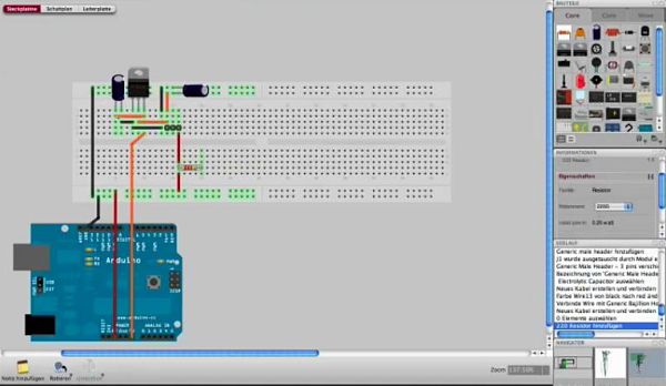
Fritzing is an open source hardware initiative that and can be used for educational, industrial or research purposes which was started at the University of Applied Sciences in Potsdam, Germany. The software allows you to document your existing Arduino wiring diagram or montage in a virtual environment and edit it or even create a new one from scratch, thanks to libraries of already made elements. The software can be downloaded for free and is available for PC, Windows and Mac.
Fritzing is a very user-friendly community driven platform where collaborative design is encouraged. You can also order custom PCBs fabricated based on your very own electronic designs.
2. EasyEDA

EasyEDA is a free web based circuit design and simulation tool developed by a team of engineers from Shenzen, China. There are certain unique features not usually found in web apps such as the SPICE simulator, a pretty refined work environment, the ability to import Kicad or Eagle files and to export the Gerber and drill fabrication files. Extensive component and model libraries are available, and users can also access models from Adafruit, Seeedstudio or Sparkfun to name just a few.
3. Upverter
Upverter is a web based EDA tool for designing circuits and PCBs online, created by three graduates of the University of Waterloo, Canada. Subscription fees start at US $99 per month for a basic membership for one editor, while a full featured package including simulation, API and scripting capabilities will cost about US $999 per month. Enterprise packages and free trials are available.

Created by CadSoft, EAGLE (Easily Applicable Graphical Layout Editor) is a CAD platform with several modules including an editor for circuit drawing. It is compatible with Windows, Linux and Mac. The features of the tool include a list with 999 sheets per schematic, components are added by drag&drop method or automatic board generation. It is an user-friendly software and has a simple interface that provides everything you need to draw the most complex circuit diagram. Pricing starts at 140 EUR, about US $155 for a single-user hobby license.

EDWinXP Is an EDA software which includes modules for drawing, simulation and testing of electronic circuits and sports a friendly interface that creates a 3D visual environment for your project. It has a 14 day free trial period and prices starting at US $440 for a basic non-commercial license.

National Instruments’ Multisim is a professional product developed by National Instruments suited for educational or industrial purposes and offers support for a detailed analysis of the design and its performance.

Circuit Diagram is a free software for Windows which allows you to exactly what its name implies — drawing circuit diagrams. Some of the components available are microcontroller, demultiplexer and inductor, however custom components can be added. Designs can be easily shared and edited with the community.

KiCad EDA is an open source CAD software suite for drawing electrical circuits, well suited for educational and industrial purposes. It’s compatible with Windows, Linux and Apple OS X.

Created by Megasys Software, PowerVue is a tool that allows you not only to draw wiring diagrams but also calculate current flows and voltage drops across them. The specifications list is huge, the software can be used to evaluate the circuit during connection or disconnection of certain components, effectively allowing you to perform debugging only on several sections or on the circuit as a whole.

DipTrace is a very powerful tool used for drawing, simulation and test verification of circuits. It can also provide accurate 3D renderings of the project. Files can be imported and exported to other EDA tools. The software is free for non-profit use for Windows, Linux and Mac, with professional licenses priced between US $75 and US $895 depending on features.

The ExpressPCB is a free CAD software suite for Windows comprised of ExpressSCH – the circuit design module, and ExpressPCB – for designing the actual PCB. It comes with a familiar interface that can be used to develop prototypes in a short time and with minimal effort. The components can be chosen from a long list and if the sketch has large dimensions, it can be divided into various sheets. Next step, after the sketch is finished, is to send to the ExpressPCB tool which allows you to create a PCB design based on your schematic, which can also be exported for fabrication. Manufacturing services are also available, starting with US $51.

5Spice is a tool designed to be used in projects with moderate complexity and does not require a long list of components. An interesting part of the software is the simulation module that can respond to problems such as noise on components or AC and DC sensitivity analysis. The software is available for Windows and may be freely used for non commercial purposes or licensed for US $319 for a single copy.

gEDA is a mature CAD tool and offers a suite of components used for electrical circuit design, schematic capture, simulation, prototyping and production. It can be used for free and is available for Linux and Mac OS X. An experimental version is also available for Windows.

With a redesigned interface to place resources at a click away, B2.Spice A/D can simulate function and display the results of the electronic circuit. Can also be used for testing and over 25 000 digital and analog parts are included in its library. The software is available for Windows and can be bought for US $595 for a single user license. A monthly subscription plan is also available for students from US $10 per month.

With SimOne you can develop, simulate and test printable circuits in a short time and with high precision. Component libraries are available as well as a graph viewer for displaying simulation results. Simulation speed is claimed to be 10 times faster than other similar products, thanks to advanced numeric algorithms employed in calculations.

Available in German and English, ProPlan is a professional product that provides a range of features to create complex circuit diagrams. It allows exporting or importing files to various PLC software and will only work with Windows OS versions and trials can be requested.

FreePCB is an open-source software which can be used by beginners and experienced users alike, who are trying to develop complex projects.


====== MA THE ELECTRONIC DRAWING CIRCUIT GO GOOD MATIC =====
4. EAGLE PCB Software

Created by CadSoft, EAGLE (Easily Applicable Graphical Layout Editor) is a CAD platform with several modules including an editor for circuit drawing. It is compatible with Windows, Linux and Mac. The features of the tool include a list with 999 sheets per schematic, components are added by drag&drop method or automatic board generation. It is an user-friendly software and has a simple interface that provides everything you need to draw the most complex circuit diagram. Pricing starts at 140 EUR, about US $155 for a single-user hobby license.
5. EDWinXP

EDWinXP Is an EDA software which includes modules for drawing, simulation and testing of electronic circuits and sports a friendly interface that creates a 3D visual environment for your project. It has a 14 day free trial period and prices starting at US $440 for a basic non-commercial license.
6. NI Multisim

National Instruments’ Multisim is a professional product developed by National Instruments suited for educational or industrial purposes and offers support for a detailed analysis of the design and its performance.
7. Circuit Diagram

Circuit Diagram is a free software for Windows which allows you to exactly what its name implies — drawing circuit diagrams. Some of the components available are microcontroller, demultiplexer and inductor, however custom components can be added. Designs can be easily shared and edited with the community.
8. KiCad EDA

KiCad EDA is an open source CAD software suite for drawing electrical circuits, well suited for educational and industrial purposes. It’s compatible with Windows, Linux and Apple OS X.
9. PowerVue Circuit Analyzer

Created by Megasys Software, PowerVue is a tool that allows you not only to draw wiring diagrams but also calculate current flows and voltage drops across them. The specifications list is huge, the software can be used to evaluate the circuit during connection or disconnection of certain components, effectively allowing you to perform debugging only on several sections or on the circuit as a whole.
It is a powerful electrical engineering software geared towards professional use which is available either as free software with limited functionality — although sufficient for most small to medium sized projects, or as a full paid version with a price tag of US $49.
10. DipTrace

DipTrace is a very powerful tool used for drawing, simulation and test verification of circuits. It can also provide accurate 3D renderings of the project. Files can be imported and exported to other EDA tools. The software is free for non-profit use for Windows, Linux and Mac, with professional licenses priced between US $75 and US $895 depending on features.
11. ExpressPCB
The ExpressPCB is a free CAD software suite for Windows comprised of ExpressSCH – the circuit design module, and ExpressPCB – for designing the actual PCB. It comes with a familiar interface that can be used to develop prototypes in a short time and with minimal effort. The components can be chosen from a long list and if the sketch has large dimensions, it can be divided into various sheets. Next step, after the sketch is finished, is to send to the ExpressPCB tool which allows you to create a PCB design based on your schematic, which can also be exported for fabrication. Manufacturing services are also available, starting with US $51.
12. 5Spice

5Spice is a tool designed to be used in projects with moderate complexity and does not require a long list of components. An interesting part of the software is the simulation module that can respond to problems such as noise on components or AC and DC sensitivity analysis. The software is available for Windows and may be freely used for non commercial purposes or licensed for US $319 for a single copy.
13. gEDA

gEDA is a mature CAD tool and offers a suite of components used for electrical circuit design, schematic capture, simulation, prototyping and production. It can be used for free and is available for Linux and Mac OS X. An experimental version is also available for Windows.
14. B2.Spice A/D
With a redesigned interface to place resources at a click away, B2.Spice A/D can simulate function and display the results of the electronic circuit. Can also be used for testing and over 25 000 digital and analog parts are included in its library. The software is available for Windows and can be bought for US $595 for a single user license. A monthly subscription plan is also available for students from US $10 per month.
15. SimOne
With SimOne you can develop, simulate and test printable circuits in a short time and with high precision. Component libraries are available as well as a graph viewer for displaying simulation results. Simulation speed is claimed to be 10 times faster than other similar products, thanks to advanced numeric algorithms employed in calculations.
16. AmpereSoft ProPlan
Available in German and English, ProPlan is a professional product that provides a range of features to create complex circuit diagrams. It allows exporting or importing files to various PLC software and will only work with Windows OS versions and trials can be requested.
17. FreePCB
FreePCB is an open-source software which can be used by beginners and experienced users alike, who are trying to develop complex projects.
Circuit diagram
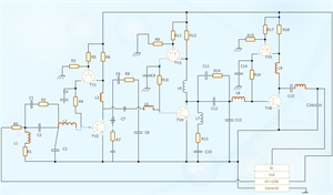
A circuit diagram (electrical diagram, elementary diagram, electronic schematic) is a graphical representation of an electrical circuit. A pictorial circuit diagram uses simple images of components, while a schematic diagram shows the components and interconnections of the circuit using standardized symbolic representations. The presentation of the interconnections between circuit components in the schematic diagram does not necessarily correspond to the physical arrangements in the finished device.[1]
Unlike a block diagram or layout diagram, a circuit diagram shows the actual electrical connections. A drawing meant to depict the physical arrangement of the wires and the components they connect is called artwork or layout, physical design, or wiring diagram.
Circuit diagrams are used for the design (circuit design), construction (such as PCB layout), and maintenance of electrical and electronic equipment.
In computer science, circuit diagrams are useful when visualizing expressions using Boolean algebra
Comparison of pictorial and schematic styles of circuit diagrams
Circuit diagrams are pictures with symbols that have differed from country to country and have changed over time, but are now to a large extent internationally standardized. Simple components often had symbols intended to represent some feature of the physical construction of the device. For example, the symbol for a resistor shown here dates back to the days when that component was made from a long piece of wire wrapped in such a manner as to not produce inductance, which would have made it a coil. These wirewound resistors are now used only in high-power applications, smaller resistors being cast from carbon composition (a mixture of carbon and filler) or fabricated as an insulating tube or chip coated with a metal film. The internationally standardized symbol for a resistor is therefore now simplified to an oblong, sometimes with the value in ohms written inside, instead of the zig-zag symbol. A less common symbol is simply a series of peaks on one side of the line representing the conductor, rather than back-and-forth as shown here.

Wire Crossover Symbols for Circuit Diagrams. Note that the CAD symbol for insulated crossing wires is exactly the same as the older, non-CAD symbol for non-insulated crossing wires. To avoid confusion, the wire "jump" (semi-circle) symbol for insulated wires in non-CAD schematics is recommended (as opposed to using the CAD-style symbol for no connection), so as to avoid confusion with the original, older style symbol, which means the exact opposite. The newer, recommended style for 4-way wire connections in both CAD and non-CAD schematics is to stagger the joining wires into T-junctions.[3]
The linkages between leads were once simple crossings of lines. With the arrival of computerized drafting, the connection of two intersecting wires was shown by a crossing of wires with a "dot" or "blob" to indicate a connection. At the same time, the crossover was simplified to be the same crossing, but without a "dot". However, there was a danger of confusing the wires that were connected and not connected in this manner, if the dot was drawn too small or accidentally omitted (e.g. the "dot" could disappear after several passes through a copy machine).[4] As such, the modern practice for representing a 4-way wire connection is to draw a straight wire and then to draw the other wires staggered along it with "dots" as connections (see diagram), so as to form two separate T-junctions that brook no confusion and are clearly not a crossover.[5][6]
For crossing wires that are insulated from one another, a small semi-circle symbol is commonly used to show one wire "jumping over" the other wire[3][7][8] (similar to how jumper wires are used).
A common, hybrid style of drawing combines the T-junction crossovers with "dot" connections and the wire "jump" semi-circle symbols for insulated crossings. In this manner, a "dot" that is too small to see or that has accidentally disappeared can still be clearly differentiated from a "jump".[3][7]
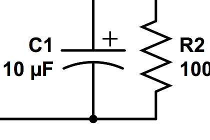
On a circuit diagram, the symbols for components are labelled with a descriptor or reference designator matching that on the list of parts. For example, C1 is the first capacitor, L1 is the first inductor, Q1 is the first transistor, and R1 is the first resistor (note that this is not written as a subscript, as in R1, L1,...). Often the value or type designation of the component is given on the diagram beside the part, but detailed specifications would go on the parts list.
Detailed rules for reference designations are provided in the International standard IEC 61346.
Organization[edit]
It is a usual although not universal convention that schematic drawings are organized on the page from left to right and top to bottom in the same sequence as the flow of the main signal or power path. For example, a schematic for a radio receiver might start with the antenna input at the left of the page and end with the loudspeaker at the right. Positive power supply connections for each stage would be shown towards the top of the page, with grounds, negative supplies, or other return paths towards the bottom. Schematic drawings intended for maintenance may have the principal signal paths highlighted to assist in understanding the signal flow through the circuit. More complex devices have multi-page schematics and must rely on cross-reference symbols to show the flow of signals between the different sheets of the drawing.
Detailed rules for the preparation of circuit diagrams, and other document types used in electrotechnology, are provided in the international standard IEC 61082-1.
Relay logic line diagrams, also called ladder logic diagrams, use another common standardized convention for organizing schematic drawings, with a vertical power supply rail on the left and another on the right, and components strung between them like the rungs of a ladder.
Common schematic diagram symbols
Artwork[edit]
Once the schematic has been made, it is converted into a layout that can be fabricated onto a printed circuit board (PCB). Schematic-driven layout starts with the process of schematic capture. The result is what is known as a rat's nest. The rat's nest is a jumble of wires (lines) criss-crossing each other to their destination nodes. These wires are routed either manually or automatically by the use of electronics design automation (EDA) tools. The EDA tools arrange and rearrange the placement of components and find paths for tracks to connect various nodes. This results in the final layout artwork for the integrated circuit or printed circuit board.[9]
A generalized design flow may be as follows:

====== MA THE ELECTRONIC DRAWING CIRCUIT GO GOOD MATIC =====


